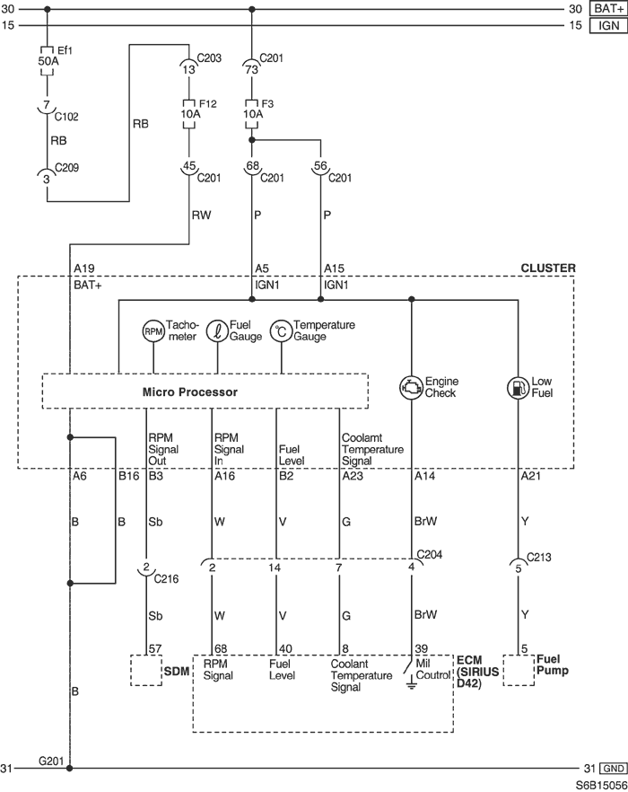
23. CLUSTER
1) TACHOMETER, FUEL GAUGE & COOLANT TEMPERATURE GAUGE : SIRIUS D42
a. CONNECTOR INFORMATION
CONNECTOR NO
(PIN NO, COLOR) | CONNECTING WIRING HARNESS | CONNECTOR POSITION |
| C102 (32 Pin, Gray) | Front - Engine Fuse Block | Engine Fuse Block |
| C201 (76 Pin, Black) | I.P - I.P Fuse Block | I.P Fuse Block |
| C203 (18 Pin, White) | I.P - I.P Fuse Block | I.P Fuse Block |
| C204 (18 Pin, Gray) | I.P - Engine | Upper Driver Leg Room |
| C209 (4 Pin, White) | Front - I.P | Front TCM |
| C213 (20 Pin, White) | I.P - Floor | Under Left A Pillar |
| C216 (12 Pin, White) | Air Bag - I.P | Behind Airconditioner |
| G201 | I.P | Upper Mirror Control Switch |
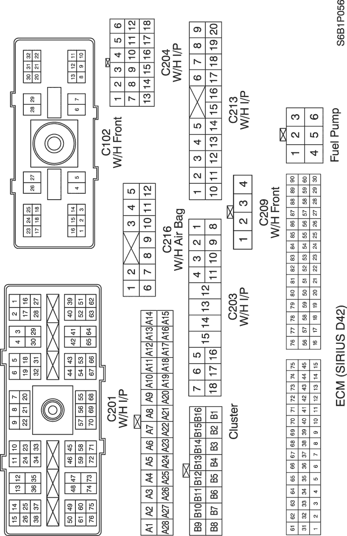
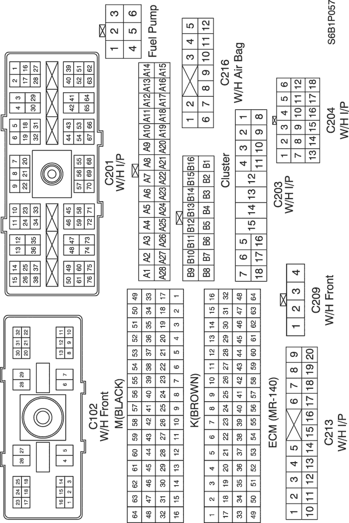
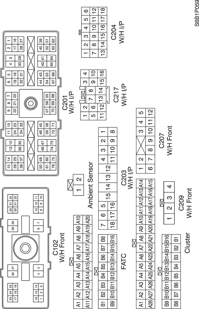
b. CONNECTOR IDENTIFICATION SYMBOL & PIN NUMBER POSITION
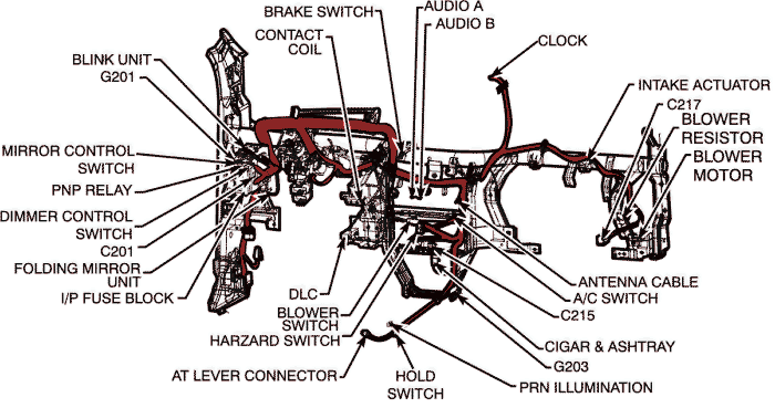
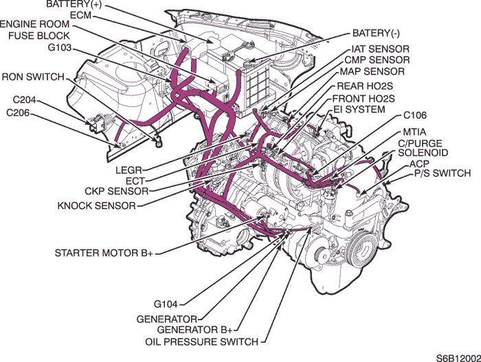
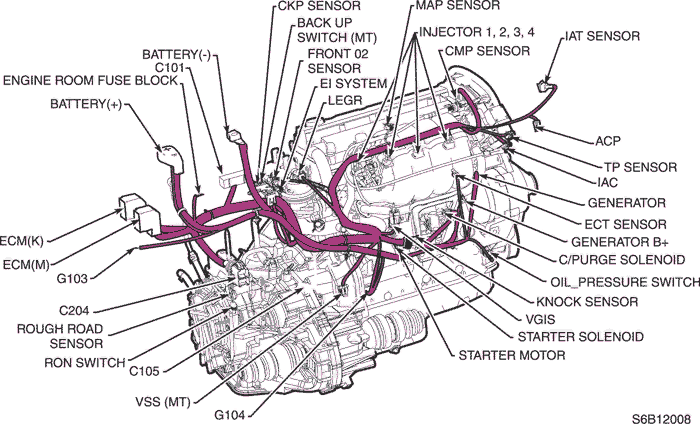
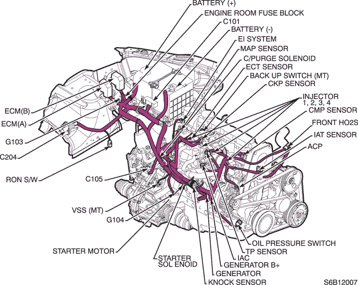
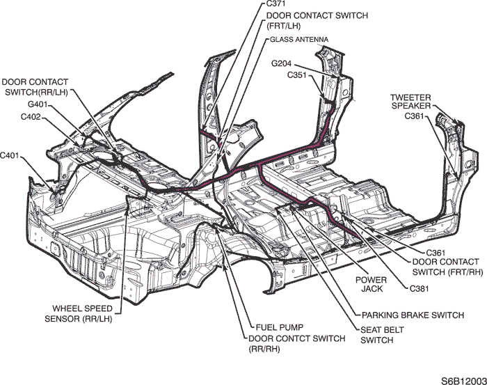
c. POSITION OF CONNECTORS AND GROUNDS
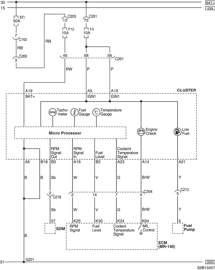
2) TACHOMETER, FUEL GAUGE & COOLANT TEMPERATURE GAUGE : MR140
a. CONNECTOR INFORMATION
CONNECTOR NO
(PIN NO, COLOR) | CONNECTING WIRING HARNESS | CONNECTOR POSITION |
| C102 (32 Pin, Gray) | Front - Engine Fuse Block | Engine Fuse Block |
| C201 (76 Pin, Black) | I.P - I.P Fuse Block | I.P Fuse Block |
| C203 (18 Pin, White) | I.P - I.P Fuse Block | I.P Fuse Block |
| C204 (18 Pin, Gray) | I.P - Engine | Upper Driver Leg Room |
| C209 (4 Pin, White) | Front - I.P | Front TCM |
| C213 (20 Pin, White) | I.P - Floor | Under Left A Pillar |
| C216 (12 Pin, White) | Air Bag - I.P | Behind Airconditioner |
| G201 | I.P | Upper Mirror Control Switch |
b. CONNECTOR IDENTIFICATION SYMBOL & PIN NUMBER POSITION
c. POSITION OF CONNECTORS AND GROUNDS
3) TACHOMETER, FUEL GAUGE & COOLANT TEMPERATURE GAUGE : HV240
a. CONNECTOR INFORMATION
CONNECTOR NO
(PIN NO, COLOR) | CONNECTING WIRING HARNESS | CONNECTOR POSITION |
| C102 (32 Pin, Gray) | Front - Engine Fuse Block | Engine Fuse Block |
| C201 (76 Pin, Black) | I.P - I.P Fuse Block | I.P Fuse Block |
| C203 (18 Pin, White) | I.P - I.P Fuse Block | I.P Fuse Block |
| C204 (18 Pin, Gray) | I.P - Engine | Upper Driver Leg Room |
| C209 (4 Pin, White) | Front - I.P | Front TCM |
| C213 (20 Pin, White) | I.P - Floor | Under Left A Pillar |
| C216 (12 Pin, White) | Air Bag - I.P | Behind Airconditioner |
| G201 | I.P | Upper Mirror Control Switch |
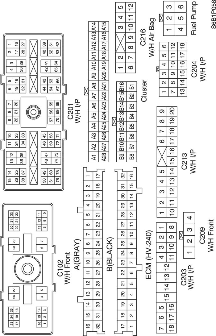
b. CONNECTOR IDENTIFICATION SYMBOL & PIN NUMBER POSITION
c. POSITION OF CONNECTORS AND GROUNDS
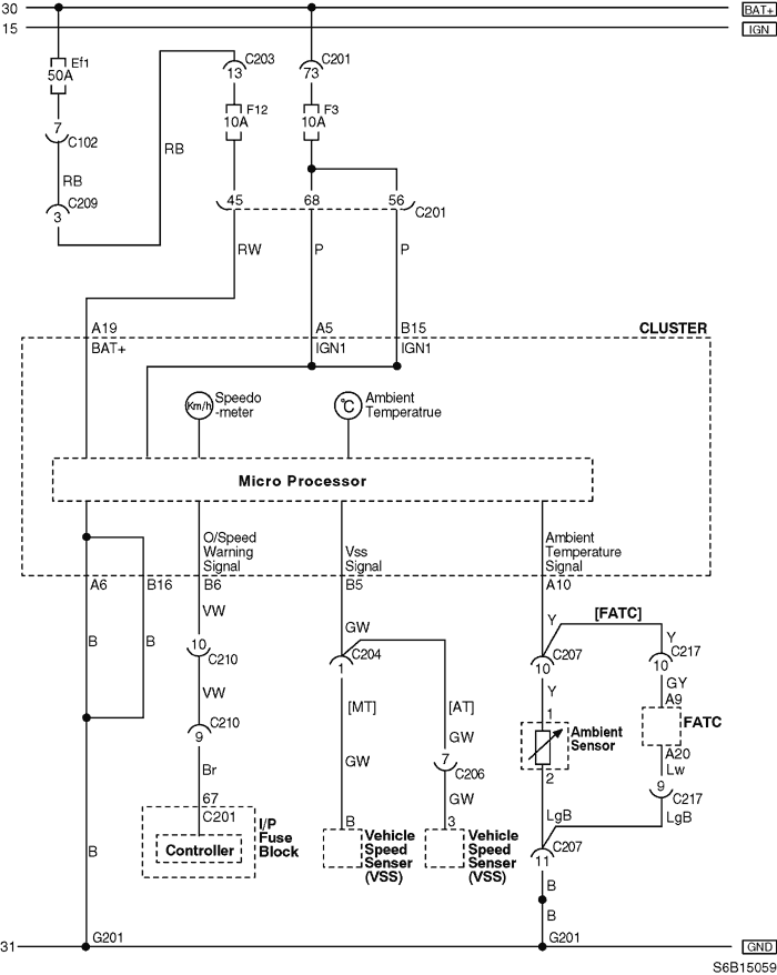
4) SPEEDOMETER & AMBIENT TEMPERATURE INDICATOR
a. CONNECTOR INFORMATION
CONNECTOR NO
(PIN NO, COLOR) | CONNECTING WIRING HARNESS | CONNECTOR POSITION |
| C102 (32 Pin, Gray) | Front - Engine Fuse Block | Engine Fuse Block |
| C201 (76 Pin, Black) | I.P - I.P Fuse Block | I.P Fuse Block |
| C203 (18 Pin, White) | I.P - I.P Fuse Block | I.P Fuse Block |
| C204 (18 Pin, Gray) | I.P - Engine | Upper Driver Leg Room |
| C207 (12 Pin, Gray) | Front - I.P | Below I.P Fuse Block |
| C209 (4 Pin, White) | Front - I.P | Front TCM |
| C217 (16 Pin, White) | I.P - FATC | Under Blower Motor |
| G201 | I.P | Upper Mirror Control Switch |
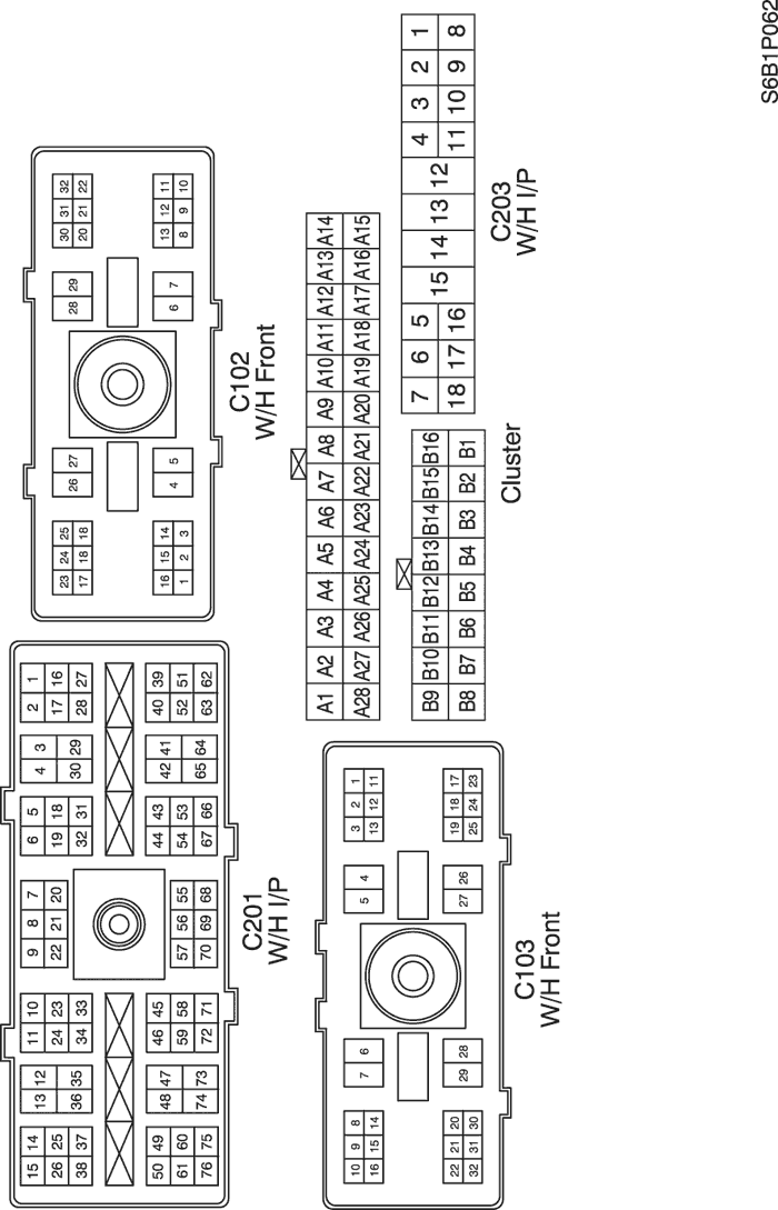
b. CONNECTOR IDENTIFICATION SYMBOL & PIN NUMBER POSITION
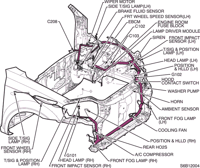
c. POSITION OF CONNECTORS AND GROUNDS
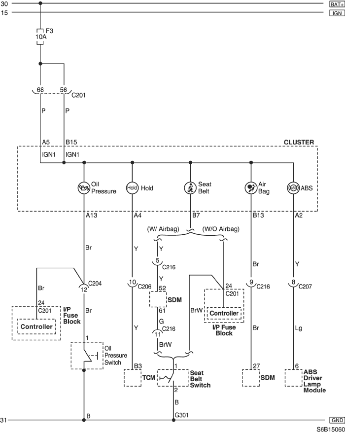
5) WARNING INDICATORS
a. CONNECTOR INFORMATION
CONNECTOR NO
(PIN NO, COLOR) | CONNECTING WIRING HARNESS | CONNECTOR POSITION |
| C201 (76 Pin, Black) | I.P - I.P Fuse Block | I.P Fuse Block |
| C204 (18 Pin, Gray) | I.P - Engine | Upper Driver Leg Room |
| C206 (10 Pin, White) | TCM - I.P | Below TCM |
| C207 (12 Pin, Gray) | Front - I.P | Below I.P Fuse Block |
| C216 (12 Pin, White) | Air Bag - I.P | Behind Airconditioner |
| G301 | Floor | Under Right Seat Cushion |
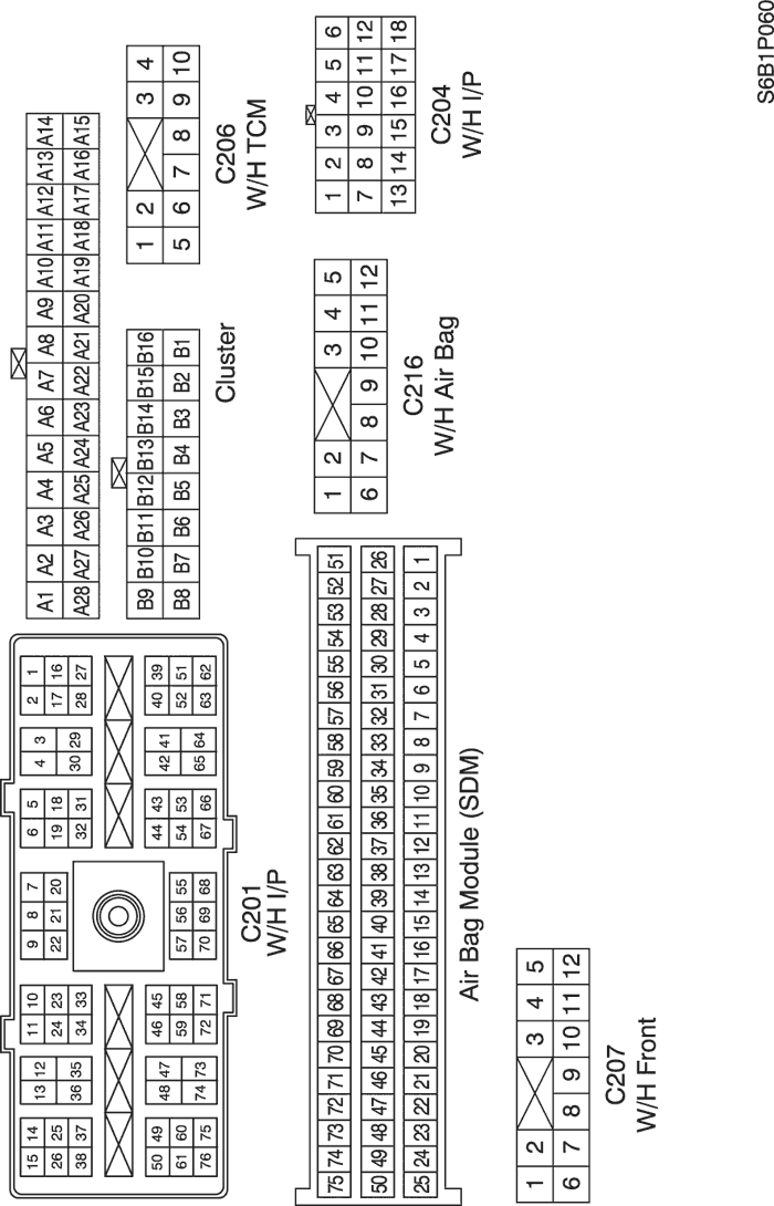
b. CONNECTOR IDENTIFICATION SYMBOL & PIN NUMBER POSITION
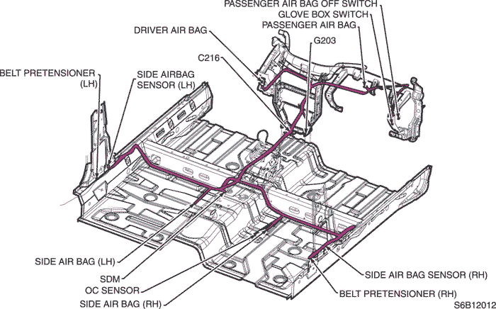
c. POSITION OF CONNECTORS AND GROUNDS
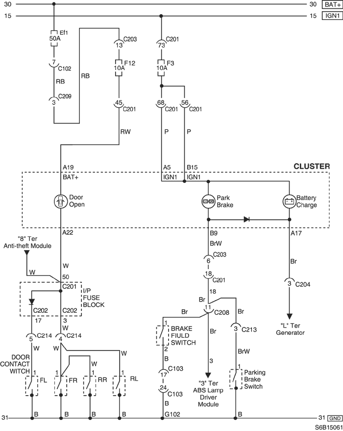
6) WARNING INDICATORS
a. CONNECTOR INFORMATION
CONNECTOR NO
(PIN NO, COLOR) | CONNECTING WIRING HARNESS | CONNECTOR POSITION |
| C102 (32 Pin, Gray) | Front - Engine Fuse Block | Engine Fuse Block |
| C103 (32 Pin, Brown) | Front - Engine Fuse Block | Engine Fuse Block |
| C201 (76 Pin, Black) | I.P - I.P Fuse Block | I.P Fuse Block |
| C202 (20 Pin, White) | I.P - I.P Fuse Block | I.P Fuse Block |
| C203 (18 Pin, White) | I.P - I.P Fuse Block | I.P Fuse Block |
| C204 (18 Pin, Gray) | I.P - Engine | Upper Driver Leg Room |
| C208 (20 Pin, Yellow) | Front - I.P | Front TCM |
| C209 (4 Pin, White) | Front - I.P | Front TCM |
| G102 | Front | Behind Left Headlamp |
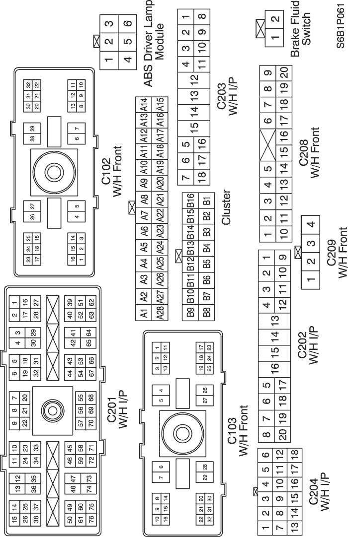
b. CONNECTOR IDENTIFICATION SYMBOL & PIN NUMBER POSITION
c. POSITION OF CONNECTORS AND GROUNDS
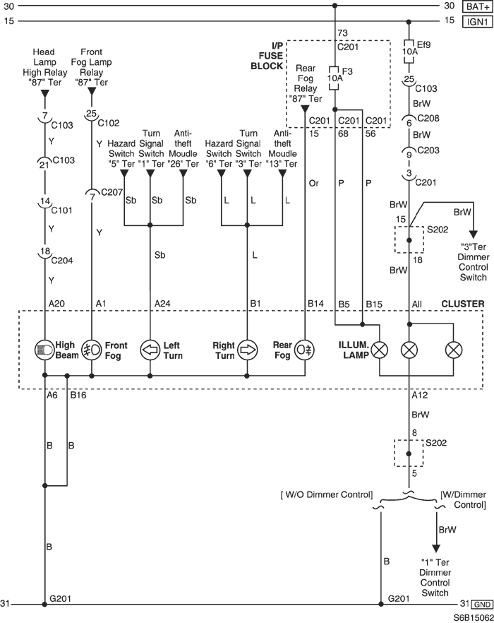
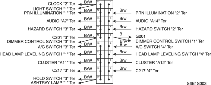
7) INDICATOR LAMP & ILLUMINATON
a. CONNECTOR INFORMATION
CONNECTOR NO
(PIN NO, COLOR) | CONNECTING WIRING HARNESS | CONNECTOR POSITION |
| C102 (32 Pin, Gray) | Front - Engine Fuse Block | Engine Fuse Block |
| C103 (32 Pin, Brown) | Front - Engine Fuse Block | Engine Fuse Block |
| C201 (76 Pin, Black) | I.P - I.P Fuse Block | I.P Fuse Block |
| C203 (18 Pin, White) | I.P - I.P Fuse Block | I.P Fuse Block |
| S202 | I.P | Behind Left Tie Bar |
| G201 | I.P | Upper Mirror Control Switch |
b. CONNECTOR IDENTIFICATION SYMBOL & PIN NUMBER POSITION
c. POSITION OF CONNECTORS AND GROUNDS
d. SPLICE PACK
S202
| © Copyright Chevrolet Europe. All rights reserved |