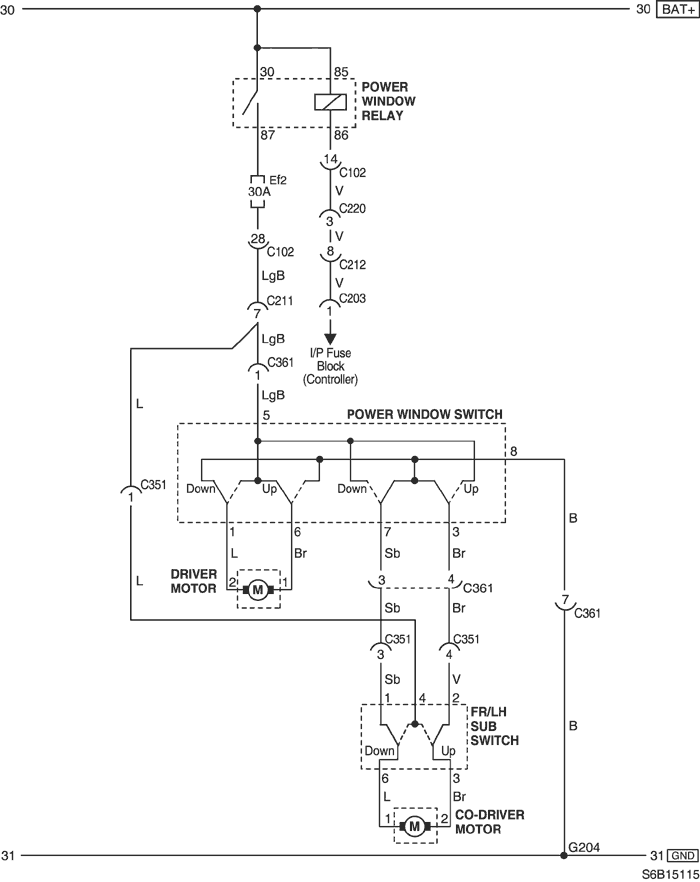
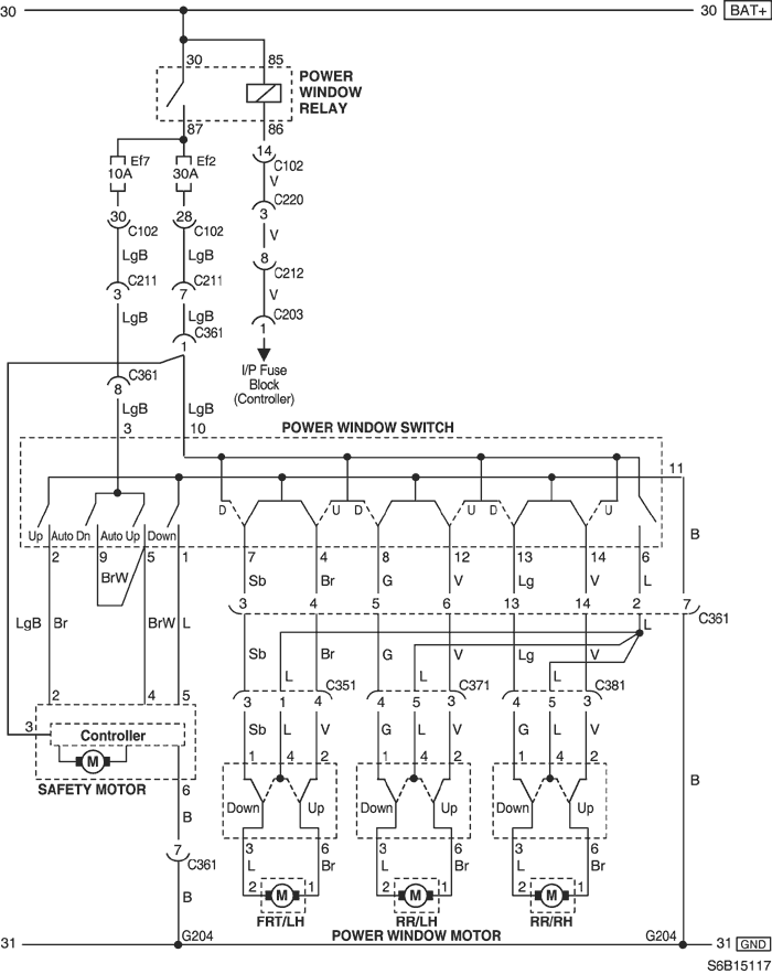
20. POWER WINDOW CIRCUIT
1) ONLY FRONT POWER WINDOW CIRCUIT
a. CONNECTOR INFORMATION
CONNECTOR NO
(PIN NO, COLOR) | CONNECTING WIRING HARNESS | CONNECTOR POSITION |
| C102 (32 Pin, Gray) | Front - Engine Fuse Block | Engine Fuse Block |
| C203 (18 Pin, White) | I.P - I.P Fuse Block | I.P Fuse Block |
| C211 (15 Pin, Yellow) | Front - Floor | Under Left A Pillar |
| C212 (15 Pin, Blue) | I.P - Floor | Below I.P Fuse Block |
| C220 (22 Pin, Black) | Front - Floor | Under Left A Pillar |
| C351 (29 Pin, White) | Floor - Front Left Door | Under Left A Pillar |
| C361 (29 Pin, White) | Floor - Front Right Door | Under Right A Pillar |
| G204 | Floor | Under Right A Pillar |
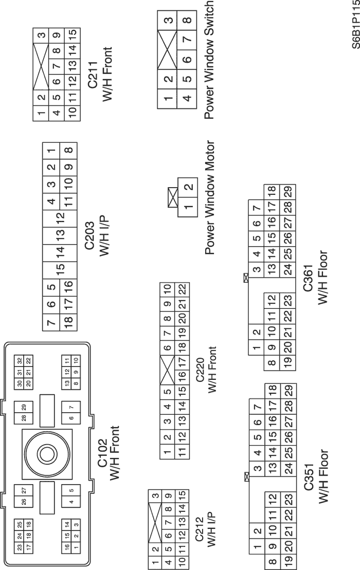
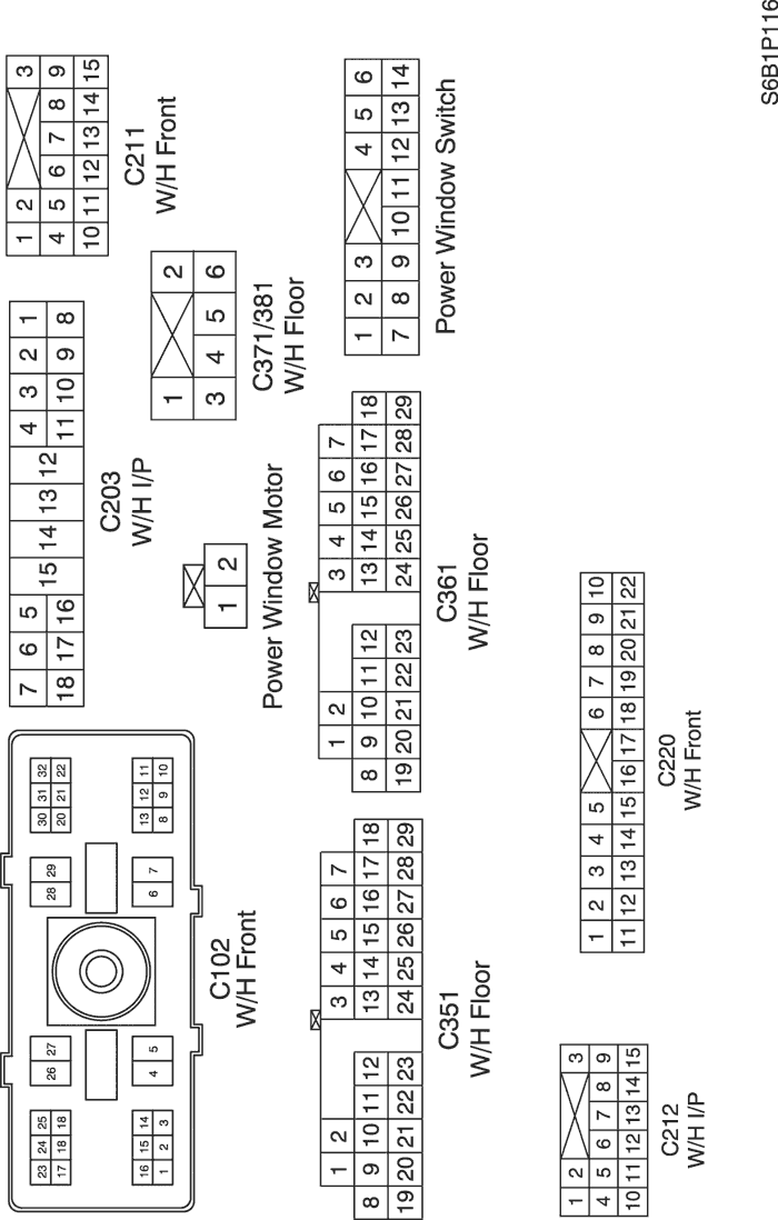
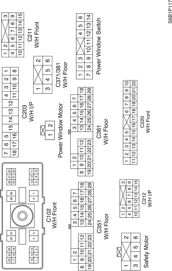
b. CONNECTOR IDENTIFICATION SYMBOL & PIN NUMBER POSITION
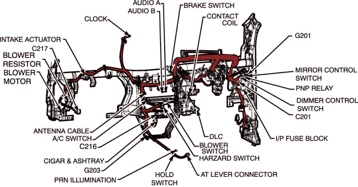
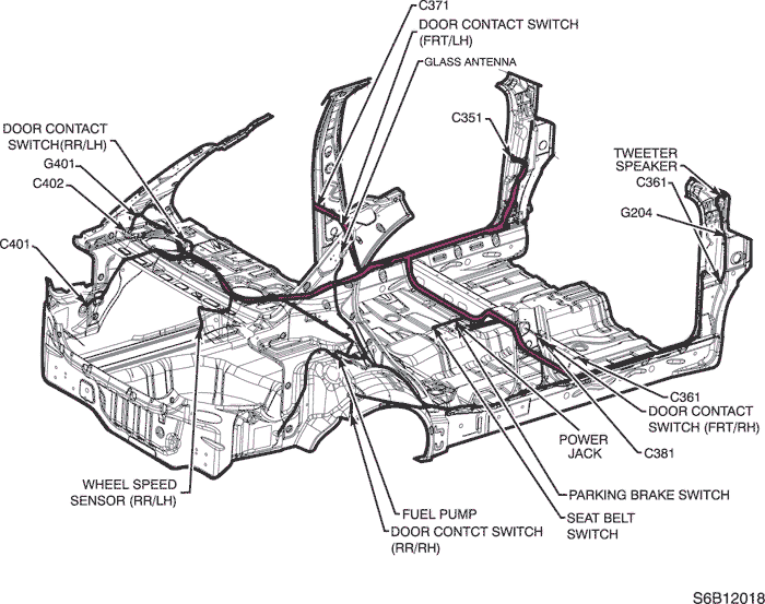
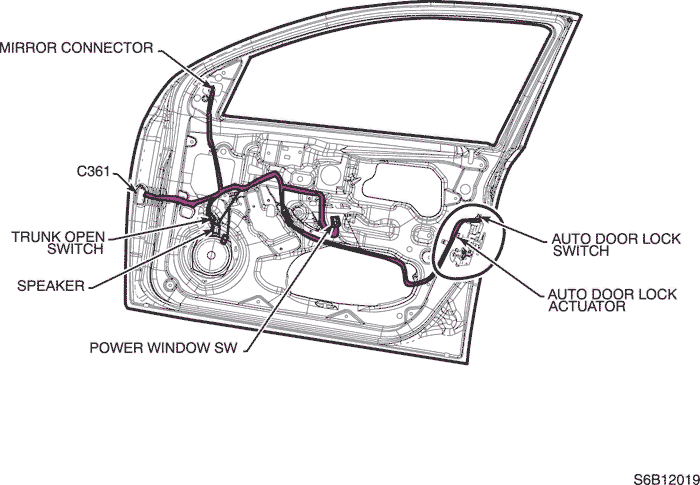
c. POSITION OF CONNECTORS AND GROUNDS
2) FRONT & REAR POWER WINDOW CIRCUIT
a. CONNECTOR INFORMATION
CONNECTOR NO
(PIN NO, COLOR) | CONNECTING WIRING HARNESS | CONNECTOR POSITION |
| C102 (32 Pin, Gray) | Front - Engine Fuse Block | Engine Fuse Block |
| C203 (18 Pin, White) | I.P - I.P Fuse Block | I.P Fuse Block |
| C211 (15 Pin, Yellow) | Front - Floor | Under Left A Pillar |
| C212 (15 Pin, Blue) | I.P - Floor | Below I.P Fuse Block |
| C220 (22 Pin, Black) | Front - Floor | Under Left A Pillar |
| C351 (29 Pin, White) | Floor - Front Left Door | Under Left A Pillar |
| C361 (29 Pin, White) | Floor - Front Right Door | Under Right A Pillar |
| C371 (6 Pin, White) | Floor - Rear Left Door | Under Left B Pillar |
| C381 (6 Pin, White) | Floor - Rear Right Door | Under Right B Pillar |
| G204 | Floor | Under Right A Pillar |
b. CONNECTOR IDENTIFICATION SYMBOL & PIN NUMBER POSITION
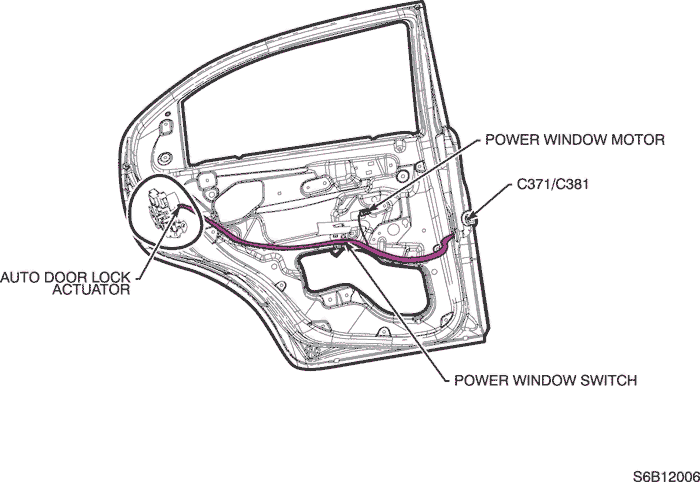
c. POSITION OF CONNECTORS AND GROUNDS
3) SAFETY POWER WINDOW CIRCUIT
a. CONNECTOR INFORMATION
CONNECTOR NO
(PIN NO, COLOR) | CONNECTING WIRING HARNESS | CONNECTOR POSITION |
| C102 (32 Pin, Gray) | Front - Engine Fuse Block | Engine Fuse Block |
| C203 (18 Pin, White) | I.P - I.P Fuse Block | I.P Fuse Block |
| C211 (15 Pin, Yellow) | Front - Floor | Under Left A Pillar |
| C212 (15 Pin, Blue) | I.P - Floor | Below I.P Fuse Block |
| C220 (22 Pin, Black) | Front - Floor | Under Left A Pillar |
| C351 (29 Pin, White) | Floor - Front Left Door | Under Left A Pillar |
| C361 (29 Pin, White) | Floor - Front Right Door | Under Right A Pillar |
| C371 (6 Pin, White) | Floor - Rear Left Door | Under Left B Pillar |
| C381 (6 Pin, White) | Floor - Rear Right Door | Under Right B Pillar |
| G204 | Floor | Under Right A Pillar |
b. CONNECTOR IDENTIFICATION SYMBOL & PIN NUMBER POSITION
c. POSITION OF CONNECTORS AND GROUNDS
| © Copyright Chevrolet Europe. All rights reserved |