Aveo | ||||||||
| ||||||||
Application | 1.2L SOHC | 1.4L
DOHC |
Maximum Speed | 157 km/h (97.6
mph) | 176 km/h
(109.4 mph) |
Minimum Turning
Radius | 5.03 m
(16.5 ft) | 5.03 m
(16.5
ft) |
Application | 1.2L SOHC | 1.4L
DOHC |
Maximum Speed | 153 km/h (95.1
mph) | 170 km/h
(105.6 mph) |
Minimum Turning
Radius | 5.03 m
(16.5 ft) | 5.03 m (16.5
ft) |
Application | 1.2L SOHC | 1.4L
DOHC |
Engine Type | In-line 4
Cylinder | In-line 4
Cylinder |
Bore | 68.5 mm (2.70
in.) | 77.9 mm (3.06
in.) |
Stroke | 78.0 mm (3.07
in.) | 73.4 mm (2.89
in.) |
Total
Displacement | 1150 cc
(70.2 in.³) | 1399 cc
(85.4 in.³) |
Compression Ratio | 9.3 : 1 | 9.5 : 1 |
Maximum
Power | 53 kw (71.1 hp)
(at 5,400 rpm) | 69 kw
(92.5 hp) (at 6,200 rpm) |
Maximum
Torque | 104 N•m (76.7
lb-ft) (at 4,400 rpm) | 130
N•m (95.9 lb-ft) (at 3,400
rpm) |
Application | 1.2L SOHC | 1.4L
DOHC |
Ignition Type | Direct Ignition
System | ← |
Ignition Timing
(BTDC) | 1° | 4° |
Ignition
Sequence | 1-3-4-2 | ← |
Spark Plug
Gap | 1.0 ~ 1.1 mm
(0.039 ~ 0.043 in.) | 1.0
~ 1.1 mm (0.039 ~ 0.043 in.) |
Spark Plug
Maker | Woojin
NGK | Woojin
NGK |
Spark Plug Type | BPR5EY-11 | BKR6E-11 |
Application | 1.2L SOHC | 1.4L
DOHC |
Type | Single Plate - Dry
Disc | Single Plate -
Dry Disc |
Outside Diameter | 184 mm (7.2 in.) | 215 mm (8.5
in.) |
Inside Diameter | 127.5 mm (5.0
in.) | 145 mm (5.7
in.) |
Thickness | 8.4 mm (0.331
in.) | 8.4 mm (0.331
in.) |
Fluid | Common Use: Brake
Fluid | Common Use: Brake
Fluid |
Application | 1.2L SOHC | 1.4L
DOHC |
Maker | DWMC | DWMC |
Type or
Model | Y4M | D-16 |
Gear Ratio
: | . | . |
3.416 :
1 1.950 : 1 1.280 :
1 0.971 : 1 0.757 :
1 3.272 : 1 | 3.545 :
1 1.952 : 1 1.276 :
1 0.971 : 1 0.763 :
1 3.333 : 1 | |
Final Drive
Ratio | 4.105 :
1 | 3.944 :
1 |
Oil Capacity | 2.1L (2.2 qt) | 1.8L (2
qt) |
Application | 1.2L SOHC | 1.4L
DOHC |
Maker | - | AISIN |
Type or
Model | - | 81-40LE |
Gear Ratio
: | . | . |
- - - - - | 2.875 :
1 1.568 : 1 1.000 :
1 0.697 : 1 2.300 :
1 | |
Final Drive Ratio | - | 4.052 |
Oil
Capacity | - | 5.6 ± 0.2L (5.9 ± 0.2
qt) |
Application | 1.2L SOHC | 1.4L
DOHC |
Booster Size | 241.3 mm (9.5
in.) | 241.3 mm (9.5
in.) |
Master Cylinder
Diameter | 22.22 mm (0.875
in.) | 22.22 mm (0.875
in.) |
Booster Ratio | 5 : 1 | 5 :
1 |
Front Brake : | . | . |
Ventilated 236
mm (9.29 in.) | Ventilated 236
mm (9.29 in.) | |
Rear Brake : | . | . |
200 mm (7.9
in.) 19.05 mm (0.750
in.) | 200 mm
(7.9 in.) 19.05 mm (0.750
in.) | |
Fluid Capacity | 0.5L (0.5 qt) | 0.5L (0.5
qt) |
Application | 1.2 L SOHC / 1.4L
DOHC | ||
Tire Size | 155/80R13 | 185/60R14 | 185/55R15 |
Standard Wheel
Size | 5.0Jx13
(Steel) | 5.5Jx14
(steel) | - |
Optional Wheel
Size | 5.5Jx14
(steel) | 5.5Jx14
(Aluminum) | 6.0Jx15
(steel) 6.0Jx15
(Aluminum) |
Temporary Spare Tire
Size | T105/70D14 | T105/70D14 | T105/70D14 |
Inflation
Pressure | . | ||
Application | 1.2L SOHC | 1.4L
DOHC |
Gear Type | Rack and Pinion | Rack and
Pinion |
Overall Gear
Ratio | . | . |
26.4 : 1 16
: 1 | 26.4 : 1 16
: 1 | |
Wheel Diameter | . | . |
380 mm (15.0
in.) - | 380 mm (15.0
in.) 370 mm (14.6
in.) | |
Wheel Alignment : (Based on 2
occupants) | . | . |
2' ±
10' 2°30' ± 45' -24' ±
45' | 2' ±
10' 2°30' ± 45' -24' ±
45' | |
15'
± 20' -1°30' ± 30' | 15'
± 20' -1°30' ± 30' | |
Oil
Capacity | 1.1L (1.2
qt) | ← |
Application | 1.2L SOHC | 1.4L
DOHC |
Front Type | Macpherson Strut | Macpherson
Strut |
Rear Type | Torsion Beam Axle | Torsion Beam
Axle |
Application | 1.2L SOHC | 1.4L
DOHC |
Fuel Delivery | MPI | MPI |
Fuel Pump
Type | Electric Motor
Pump | Electric Motor
Pump |
Fuel Filter Type | Cartridge | Cartridge |
Fuel
Capacity | 45L (11.9
gal) | 45L (11.9
gal) |
Application | 1.2L SOHC | 1.4L
DOHC |
Lubricating Type | Forced Feed | Forced Feed |
Oil Pump
Type | Rotary
(Trochoid) | Rotary
(Trochoid) |
Oil Filter Type | Cartridge (Full
Flow) | Cartridge (Full
Flow) |
Oil Pan Capacity | . | . |
3.2L (3.4
qt) | 3.75L (3.96
qt) |
Application | 1.2L SOHC | 1.4L
DOHC | |
Cooling Type | Forced
Water Circulation | Forced Water | Circulation |
Radiator
Type | Cross-flow | Cross-flow | |
Water Pump
Type | Centrifugal | Centrifugal | |
Thermostat
Type | Pellet
Type | Pellet
Type | |
Coolant Capacity
: | 4.2L (4.4
qt) | 6.0L (6.3
qt) |
Application | 1.2L SOHC | 1.4L
DOHC |
Battery | 12V-45 AH 430 Cold
Cranking Amps | 12V-55
AH 550 Cold Cranking
Amps |
Generator | 12V-80A | 12V-85A |
Starter | 0.8 KW | 1.2
KW |
Application | 1.2L SOHC | 1.4L
DOHC | |
Overall Length : | . | . | . |
4,310 mm
(169.7 in.) | 4,310 mm
(169.7 in.) | ||
Overhang : | . | . | |
833 mm (32.8
in.) | 833 mm (32.8
in.) | ||
997
mm (39.3 in.) | 997
mm (39.3 in.) | ||
Overall Width | 1,710 mm (69.3
in.) | 1,710 mm (69.3
in.) | |
Overall Height | 1,505 mm (59.3
in.) | 1,505 mm (59.3
in.) | |
Minimum Ground
Clearance | 155 mm (6.1
in.) | 155 mm (6.1
in.) | |
Wheel Base | 2,480 mm (97.6
in.) | 2,480 mm (97.6
in.) | |
Tread : | . | . | |
1,450 mm (57.1
in.) 1,430 mm (56.3 in.) | 1,450 mm (57.1
in.) 1,430 mm (56.3
in.) |
Application | 1.2L SOHC | 1.4L
DOHC |
Manual : | . | . |
997 kg
(2,198.0 lb) 1,047 kg (2,308.2
lb) | 1,060 kg
(2,336.9 lb) 1,110 kg (2,447.1
lb) | |
1,490 kg (3,284.9
lb) | 1,540 kg (3,395.1
lb) | |
Automatic : | . | . |
- - | 1,052 kg
(2,319.3 lb) 1,115 kg (2,458.2
lb) | |
- | 1,545 kg (3,406.1
lb) | |
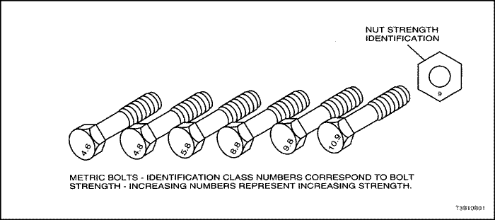
5 | 5 |
Bolt* | 4T - Low Carbon
Steel | 7T -
High Carbon Steel | 7T - Alloy
Steel |
M6 X 1.0 | 4.1-8.1 N•m (36-72
lb-in) | 5.4-9.5 N•m (48-84
lb-in) | - |
M8 X
1.25 |
8.1-17.6 N•m (72-156 lb-in) | 12.2-23.0 N•m
(108-204 lb-in) | 16-30 N•m (12-22
lb-ft) |
M10 X 1.25 | 20-34 N•m (15-25 lb-ft)
| 27-46 N•m (20-34
lb-ft) | 37-62
N•m (27-46 lb-ft) |
M10 X 1.5
| 19-34 N•m
(14-25 lb-ft) | 27-45 N•m (20-33 lb-ft)
| 37-60 N•m (27-44
lb-ft) |
M12 X 1.25 | 49-73 N•m (36-54 lb-ft)
| 61-91 N•m (45-67
lb-ft) | 76-114
N•m (56-84 lb-ft) |
M12 X
1.75 | 45-69
N•m (33-51 lb-ft) | 57-84 N•m (42-62 lb-ft)
| 72-107 N•m
(53-79 lb-ft) |
M14 X 1.5 | 76-115 N•m (56-85 lb-ft)
| 94-140 N•m
(69-103 lb-ft) | 114-171 N•m (84-126 lb-ft)
|
M14 X 2.0 |
72-107 N•m (53-79 lb-ft) | 88-132 N•m (65-97 lb-ft)
| 107-160 N•m
(79-118 lb-ft) |
M16 X 1.5 | 104-157 N•m (77-116 lb-ft)
| 136-203 N•m
(100-150 lb-ft) | 160-240 N•m (118-177
lb-ft) |
M16 X 2.0 | 100-149 N•m (74-110 lb-ft)
| 129-194 N•m
(95-143 lb-ft) | 153-229 N•m (113-169
lb-ft) |
M18 X 1.5 | 151-225 N•m (111-166
lb-ft) | 195-293
N•m (144-216 lb-ft) | 229-346 N•m (169-255
lb-ft) |
M20 X 1.5 | 206-311 N•m (152-229
lb-ft) | 270-405
N•m (199-299 lb-ft) | 317-476 N•m (234-351
lb-ft) |
M22 X 1.5 | 251-414 N•m (185-305
lb-ft) | 363-544
N•m (268-401 lb-ft) | 424-636 N•m (313-469
lb-ft) |
M24 X 2.0 | 359-540 N•m (265-398
lb-ft) | 431-710
N•m (318-524 lb-ft) | 555-831 N•m (409-613
lb-ft) |
* Diameter X pitch in
millimeters | |||
Maintenance
Item | Maintenance
Interval | ||||||||
. | Kilometers or time in
months, whichever comes
first | ||||||||
x
1,000 km | 15 | 30 | 45 | 60 | 75 | 90 | 105 | 120 | |
x 1,000
miles | 10 | 20 | 30 | 40 | 50 | 60 | 70 | 80 | |
Months | 12 | 24 | 36 | 48 | 60 | 72 | 84 | 96 | |
| Drive belts(Alternator, power steering and A/C belt) - 1.4 D | I | I | I | I | |||||
| Drive Belt (Alternator) - 1.2 S | I | I | R | I | I | R | I | I | |
| Drive Belt (Power Steering, A/C) - 1.2 S | I | I | I | I | R | I | I | I | |
Engine oil & engine oil
filter (1) (3) | R | R | R | R | R | R | R | R | |
Cooling system hose &
connections | I | I | I | I | I | I | I | I | |
Engine coolant
(3) | Silicate
based | I | I | R | I | I | R | I | I |
Dex-Cool (4) | See the remark (4)
below. | ||||||||
Fuel filter | . | . | R | . | . | R | . | . | |
Fuel line and
connections | I | I | I | I | I | I | I | I | |
Air cleaner element
(2) | I | I | R | I | I | R | I | I | |
Spark plugs | I | R | I | R | I | R | I | R | |
Spark plug
wires | Replace every 96,000
km(60,000 miles) | ||||||||
Value Clearance - (1.2 S
Only) | I | I | I | I | I | I | I | I | |
EVAP canister & vapor
lines | . | . | I | . | . | I | . | . | |
PCV system | . | I | . | I | . | I | . | I | |
Timing belt - 1.4
D | . | l | . | R | . | l | . | R | |
Timing belt - 1.2
S | . | l | . | I | . | R | . | I | |
Maintenance
Item | Maintenance
Interval | ||||||||
. | Kilometers or time in
months, whichever comes
first | ||||||||
x
1,000 km | 15 | 30 | 45 | 60 | 75 | 90 | 105 | 120 | |
x 1,000
miles | 10 | 20 | 30 | 40 | 50 | 60 | 70 | 80 | |
Months | 12 | 24 | 36 | 48 | 60 | 72 | 84 | 96 | |
| Interior air filter (A/C) (8) | R | R | R | R | R | R | R | R | |
| Exhaust pipes & mountings | I | I | I | I | I | I | I | I | |
| Brake/Clutch fluid (3) (4) | I | R | I | R | I | R | I | R | |
Rear brake drums and
linings (5) | I | I | I | I | I | I | I | I | |
Front brake pads and discs
(5) | I | I | I | I | I | I | I | I | |
Parking brake | I | I | I | I | I | I | I | I | |
Brake line and conne4ctions
(Including booster) | I | I | I | I | I | I | I | I | |
Manual Transaxle Oil - 1.2
S (3) | R | I | R | I | R | I | R | I | |
Manual Transaxle Oil - 1.4
D (3) | I | I | I | I | I | I | I | I | |
Automatic transaxle fluid
(3) |
I | I | I | I | I | I | I | I | |
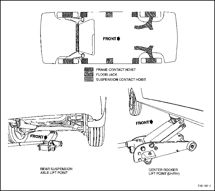
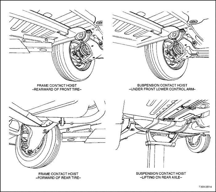
Tighten chassis and
underbody bolts and nuts | I | I | I | I | I | I | I | I | |
Wheel alignment
(6) | Inspect when
abnormal condition is
noted | ||||||||
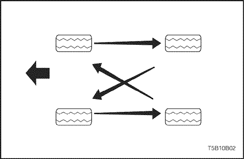
Tire condition &
inflation pressure (7) | See the remark
below | ||||||||
Steering wheel and
linkage | I | I | I | I | I | I | I | I | |
Power steering fluid &
lines (3) | I | I | I | I | I | I | I | I | |
Drive shaft
boots | I | I | I | I | I | I | I | I | |
Seat belts, buckles and
anchors | I | I | I | I | I | I | I | I | |
Lubrcate locks, hinges and
hood latch | I | I | I | I | I | I | I | I | |
Usage | Capacity | Fluid/Lubricant |
Engine Oil | 3.2L (3.4 qt) : 1.2L
S 3.75L (3.96 qt) : 1.4L
D | API SL (ILSAC
GF-IV) grade SAE 5W-30 Hot area : SAE
10W-30 |
Engine Coolant | 4.2L (4.4 qt) : 1.2L
S 6.0L (6.3 qt) : 1.4L D | Silicate based coolant/Dex-cool
coolant |
Brake Fluid and Clutch
Fluid | 0.5L
(0.5 qt) | DOT-3 or
DOT-4 |
Power Steering
System | 1.1L
(1.2 qt) | DEXRON®-IID |
Automatic
Transaxle | 5.6 ±
0.2L (5.9 ± 0.2 qt) : 1.4L D | ESSO JWS 3309 or TOTAL FLUID
III G |
Manual Transaxle | 2.1L (2.2 qt) : 1.2L
S 1.8L (2.0 qt) : 1.4L D | SAE75W85W : 1.2L
S SAE75W90 : 1.4L D |
Manual Transaxle
Shift Linkage | As
required | Multipurpose type grease
meetingrequirements NLGI No. 1 or
2 |
Key Lock
Cylinders | As
required | Silicone
lubricant |
Automatic Transaxle
ShiftLinkage | As
required | Engine
oil |
Clutch Linkage Pivot
Points | As
required | Engine
oil |
Floor Shift Linkage
Points | As
required | Engine
oil |
Hood Latch
Assembly a. Pivots and Spring
Anchor b. Release Pawl | As required | a. Engine oil b.
Multipurpose type grease meetingrequirements
NLGI No. 1 or 2 |
Hood and door
hinges Fuel door hinge Rear
compartment lid hinges | As required | Engine oil |
Weatherstrips | As required | Silicone
grease |
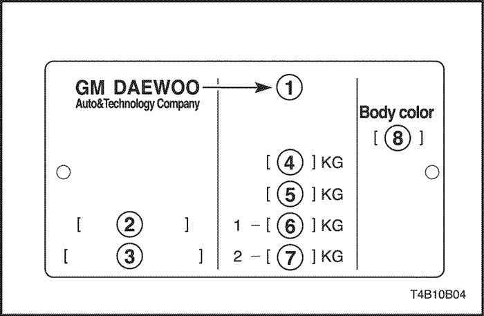
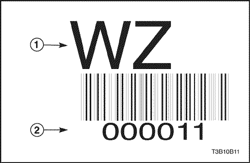
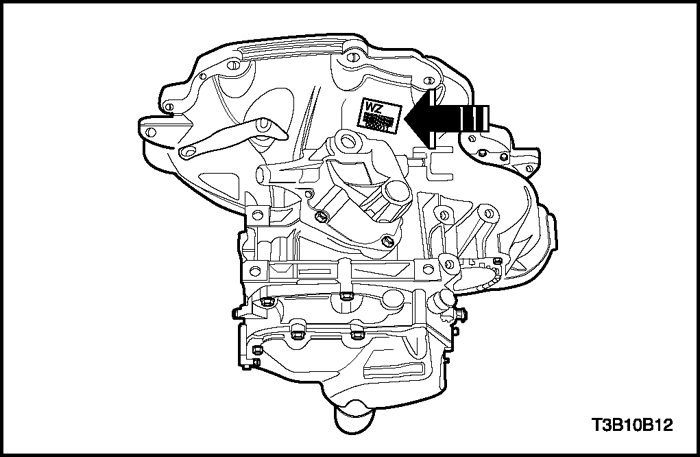
Identification Code | Engine | Gear
Ratio |
SY | 1.4L DOHC | 3.944 |
| © Copyright Chevrolet Europe. All rights reserved |


