SECTION
MAINTENANCE AND REPAIR
ON-VEHICLE SERVICE


Generator (1.2 SOHC)
Removal Procedure
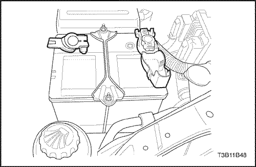
- Disconnect the negative battery cable.
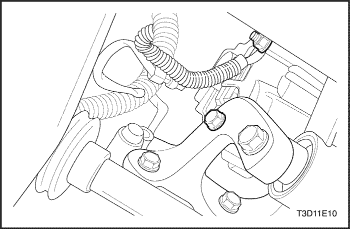
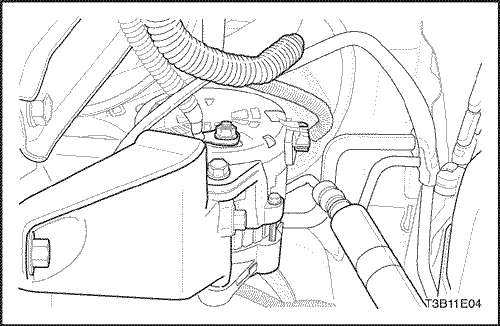
- Disconnect the harness connector.
- Remove the battery harness connector nut to disconnect the battery positive connector (1).
- Disconnect the generator harness connector (2).
- Remove the generator drive belt.
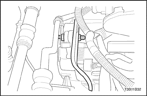
- Loosen the generator adjusting bolt (1).
- Remove the lower bracket-to-generator bolt and nut (2).
- Separate the generator drive belt from the generator.
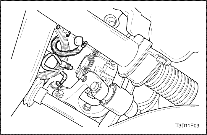
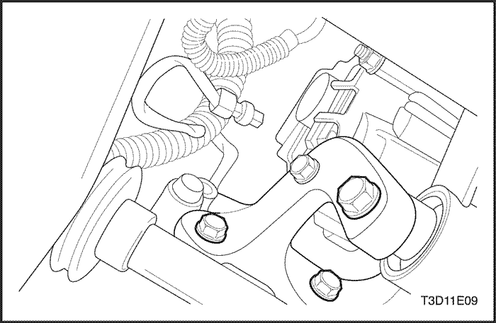
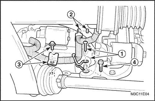
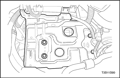
- Remove the engine mounting lower bracket.
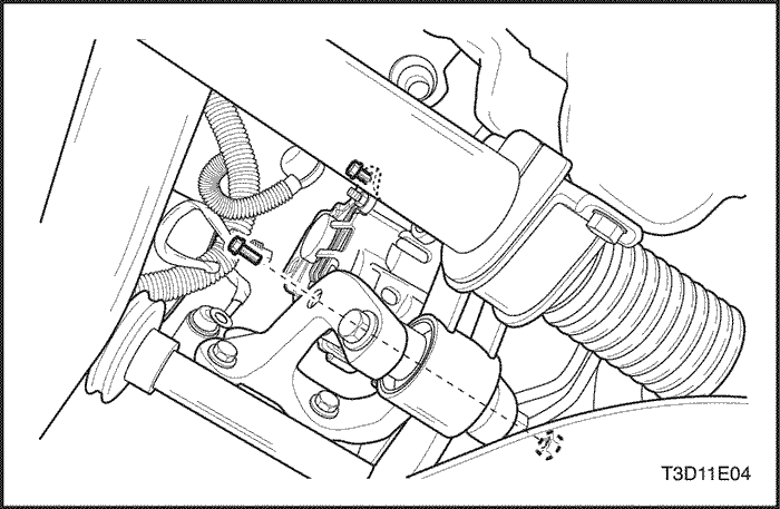
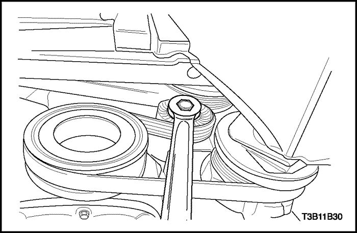
- Remove the engine mounting lower bracket, attaching reaction rod bolt and nut (1).
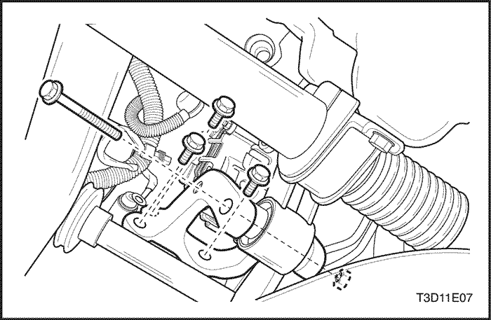
- Remove the engine mounting lower bracket bolts (2).
- Remove the engine mounting lower bracket (3).
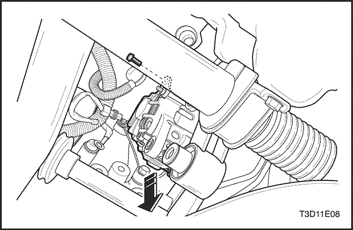
- Remove the generator.
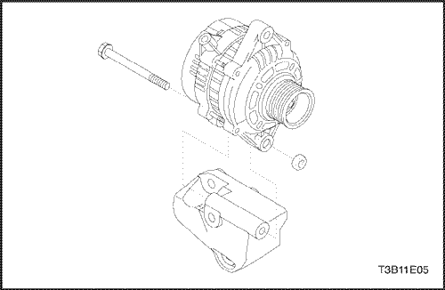
- Remove the generator adjusting bolt (1).
- Carefully remove the genrator (2).
Installation Procedure
- Install in the reverse order of removal except generator driver velt.
- Install the engine mounting lower bracket bolts and nut.
Tighten
- Tighten the engine mounting lower bracket bolts to 35-41 N•m (25-30 lb-ft) (a).
- Tighten the engine mounting lower bracket, attaching reaction rod bolt and nut to 68-83 N•m (50-61 lb-ft) (b).
- Install the bolts and nut.
Tighten
- Tighten the generator adjusting bolt to 4-7 N•m (35-62 lb-in) (a).
- Tighten the generator lower bracket bolt and nut to 18-28 N•m (13-21 lb-ft) (b).
- Inspect the generator drive belt tension.
Generator (1.4 DOHC)
Removal Procedure
- Disconnect the negative battery cable.
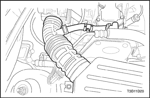
- Disconnect the intake air temperature (IAT) sensor electrical connector from the air intake tube.
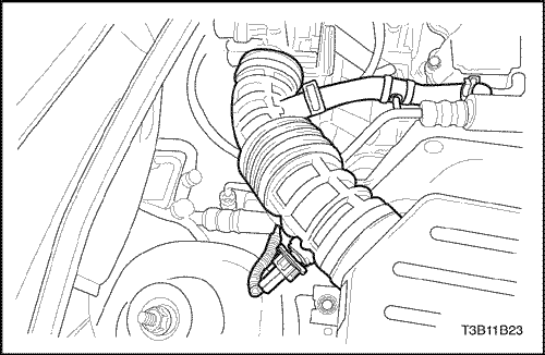
- Remove the breather tube clamp and all other clamps to remove the air intake tube.
- Remove the battery harness connector nut from the generator.
- Remove the generator shackle bracket bolt.
- Remove the serpentine accessory drive belt. For vehicles equipped with power steering and air conditioning, Refer to Section 6B, Power Steering Pump.
- Remove the nuts which hold the generator lower bracket- to - generator bolts.
- Carefully remove the generator.
Installation Procedure
- Install the generator at the generator lower bracket and insert the generator bolts.
- Install the nut and the washers on the generator lower bracket-to-generator bolts.
Tighten
Tighten the generator lower bracket-to-generator nuts to 25 N•m (18 lb-ft).
- Install the generator and the lower support bracket assembly to the engine block with the bolts.
- Secure the generator to the shackle bracket with the bolt.
Tighten
Tighten the generator shackle bracket bolt to 25 N•m (18 lb-ft).
- Connect the harness connector to the back of the generator.
- Install the generator lead to the battery and fasten the lead with the nut.
Tighten
Tighten the generator battery lead nut to 15 N•m (11 lb-ft).
- Install the air intake tube and the connector.
- Install the IAT electrical connector to the air intake tube.
- Connect the negative battery cable.
Starter (1.2 SOHC)
Removal Procedure
- Disconnect the negative battery cable.
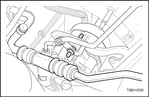
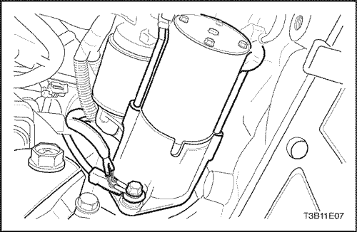
- Disconnect the electrical connector and clip around the starter.
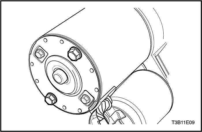
- Remove the engine oil temperature sensor to disconnect the harness connector (1).
- Remove the starter solenoid nut to disconnect the electrical cable (2).
- Remove the harness clip bolt to disconnect the harness clip (3).
- Remove the ground bolt (4).
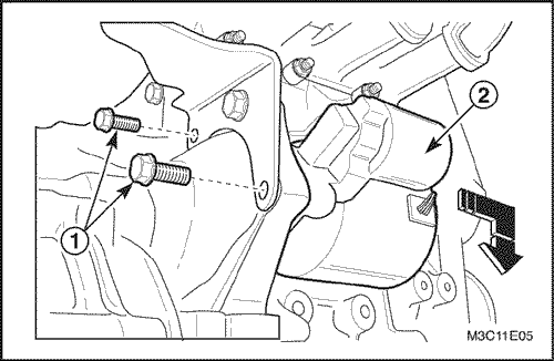
- Remove the starter assembly.
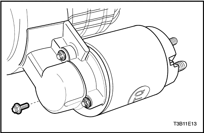
- Remove the starter mounting bolts (1).
- Remove the starter assembly (2).
Installation Procedure
- Install in the reverse order of removal.
- Install the starter mounting bolts and starter solenoid nut.
Tighten
- Tighten the starter mounting bolts to 23 N•m (17 lb-ft).
- Tighten the starter solenoid nut to 9-12 N•m (80-106 lb-in).
- Tighten the harness clip bolt to 9-12 N•m (80-106 lb-in).
- Tighten the ground bolt to 35-41 N•m (26-30 lb-ft).
Starter (1.4 DOHC)
Removal Procedure
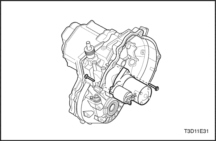
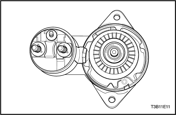
- Remove the upper and the lower starter mounting bolts.
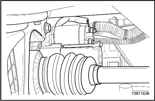
- Remove the starter solenoid nuts to disconnect the electrical cable.
- Remove the starter assembly.
Installation Procedure
- Place the starter assembly in position.
- Install the upper and the lower starter mounting bolts.
Tighten
Tighten the starter mounting bolts to 43 N•m (32 lb-ft).
- Position the starter electrical wire on the solenoid terminal.
- Install the starter solenoid nuts.
Tighten
Tighten the starter solenoid nuts to 15 N•m (11 lb-ft).
Battery/Battery Tray
Removal Procedure
- Disconnect the negative battery cable and then disconnect the positive battery cable.
- Remove the nuts from the battery rods that fasten the battery hold-down bar clamp.
- Check the battery carrier tray for obvious cracks or damage. Detach the carrier tray if necessary by removingthe upper and the lower bolts.
Installation Procedure
- Install the battery carrier by fastening the carrier tray upper and lower bolts.
Tighten
Tighten the battery carrier tray upper and the lower bolts to 20 N•m (15 lb-ft).
- Install the battery into the tray.
- Fasten the bar clamp to the battery by loosely attaching the battery rods from the battery tray cutouts through the bar clamp holes, and loosely tightening the nuts.
Tighten
Tighten the battery retainer clamp-to-battery rod nuts to 4 N•m (35 lb-in).
- Connect the negative battery cables.
Tighten
Tighten the battery cable nuts to 4.5 N•m (40 lb-in).
UNIT REPAIR
Starter Motor (1.2 SOHC)
Inspection / Measurement (Before the Overhaul)
- Remove the starter. Refer to "Starter" in this section.
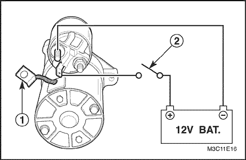
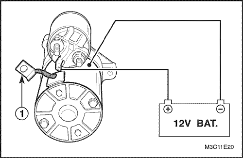
- Pinion clearance inspection.
- Disconnect the starter motor terminal M (1).
- Connect the 12-volt battery lead to the starter motor terminals M and S.
Notice : Complete the testing in a minimum amount of time to prevent overheating and damaging the solenoid. (in 10 seconds)
- Switch on to move the pinion gear (2).
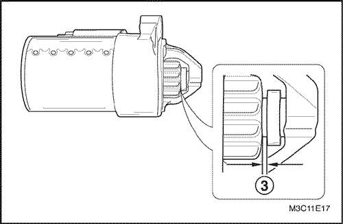
- Now check the clearance between the pinion and the stopper with the filler gauge (3).
- If the clearance does not fall within the limits, check for improper installation and replace all worn parts.
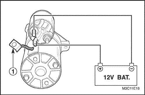
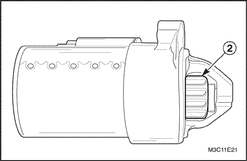
- Magnetic switch pull-in test.
- Disconnect the starter motor terminal M (1).
- Connect the 12-volt battery lead to the starter motor terminals M and S.
Notice : Complete the testing in a minimum amount of time to prevent overheating and damaging the solenoid. (in 10 seconds)
- Inspect the pinion gear's moving to the outside (2).
- If the pinion gear does not move outside, replace the magnetic switch.
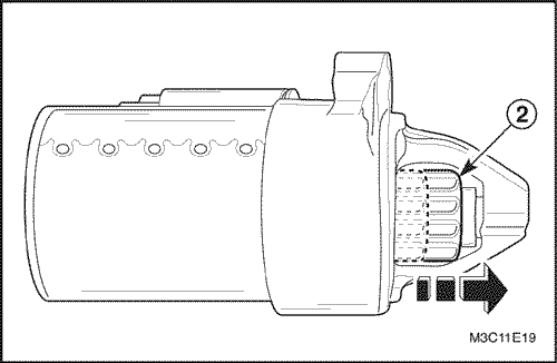
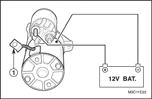
- Solenoid hold-in test.
- Disconnect the starter motor terminal M (1).
- Connect the 12-volt battery lead to the starter motor terminal S and body.
Notice : Complete the testing in a minimum amount of time to prevent overheating and damaging the solenoid.
- Check the pinion gear's moving to the outside (2).
- If the pinion gear move to the inside, the circuit is open. Replace the magnetic switch.
- Solenoid return test.
- Disconnect the starter motor terminal M (1).
- Connect the 12-volt battery lead to the starter motor terminal S and body.
Notice : Complete the testing in a minimum amount of time to prevent overheating and damaging the solenoid.
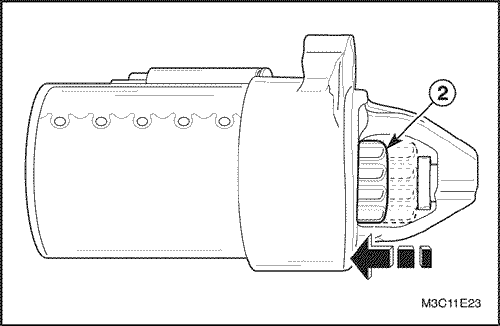
- Check the returning speed of pinion gear (2). If the returning speed is fast, the operation is normal.
- Replace the solenoid if the operation is abnormal.
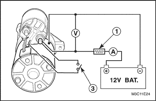
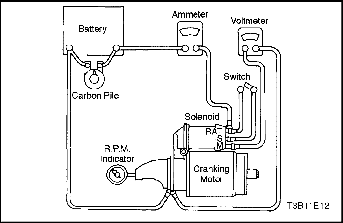
- No-road test.
- Connect the 12-volt battery lead to the starter circuit.
- Connect the current and the voltage (1).
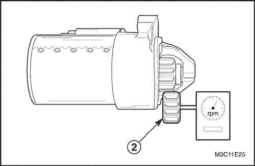
- Install the starter motor rpm gage (2).
- Start the starter motor with the switch on (3).
- Measure the speed of pinion gear and the current.
- If the measurement satisfy the limit, the starter motor is normal.
Desciption | Limit |
The speed of pinion gear | Minimum : 2,000 rpm |
Condition : Voltage / Current | Maximum : 9V / 150A |
- Replace the starter motor if necessary.
Disassembly Procedure
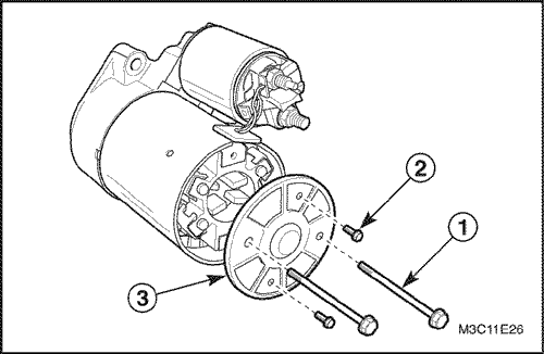
- Remove the starter contact end frame.
- Remove the through-bolts (1).
- Remove the contact end frame bolts (2).
- Remove the frame with the spacer (3).
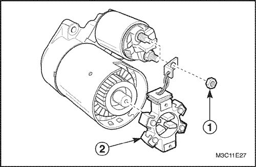
- Remove the brush holder assembly.
- Remove the starter motor terminal M nut (1).
- Remove the brush holder assembly (2).
- Remove the field frame assembly from the armature set (1).
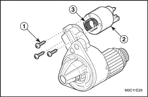
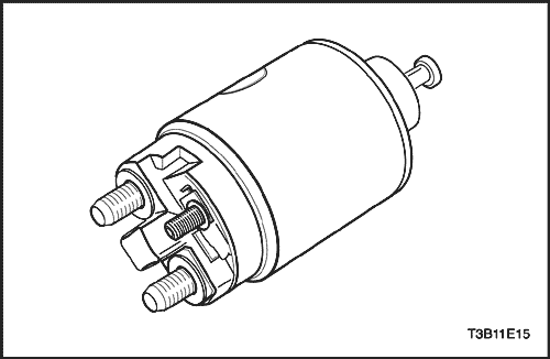
- Remove the solenoid assembly.
- Remove the solenoid screws (1).
- Remove the magnetic switch (2).
- Remove the spring (3).
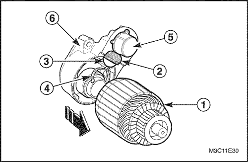
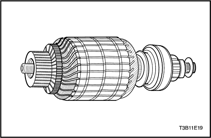
- Remove the armature set and solenoid from the starter housing.
- Remove the armature set (1).
- Remove the rubber sealer (2).
- Remove the shift lever plate (3).
- Remove the shift lever (4).
- Remove the solenoid (5).
- Remove the gasket (6).
Inspection / Measurement (After the Overhaul)
- Ground test for armature coil.
- Inspect the insulation between commutator and armature coil using the voltmeter.
- Replace the armature assembly if necessary.
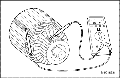
- Short circuit test for armature coil.
- If test equipment is available, check the armature for short circuit by placing it on a growler, and holding back a saw blade over the armature core while the armature is rotated. If the saw blade vibrates, replace the armature.
- Open circuit test for armature coil.
- Check the continuity between the commutator bars using multimeter.
- Replace the armature assembly if necessary.
- Inspect the brushes wear.
- Inspect the brushes, the pop-out springs and the brush holder for wear and damage. Replace the brushes, if necessary.
- Brushes wear limit.
Descipt-ion | Standard | Limit |
Brushes wear | 11.3-11.5 mm (0.445-0.453 in) | 7.0-7.25 mm (0.275-0.285 in) |
Assembly Procedure
- Install in the reverse order of removal.
- Install the bolts / nuts.
Tighten
- Tighten the starter motor terminal M nut to 9-12 N•m (80-106 lb-in) (a).
- Tighten the through-bolts to 4-6 N•m (35-53 lb-in) (b).
Starter Motor (1.4 DOHC)
Disassembly Procedure
- Remove the starter. Refer to "Starter" in this section.
- Remove the starter through-bolts.
- Remove the commutator end frame and brush holder assembly.
- Inspect the brushes, the pop-out springs, and the brush holders for wear and damage. Replace the assembly, if needed.
- Check the armature to see if it turns freely. If the armature does not turn freely, break down the assembly immediately, starting with Step 14. Otherwise, give the armature a no-load test.
Notice : Complete the testing in a minimum amount of time to prevent overheating and damaging the solenoid.
Important : If the specified current draw does not include the solenoid, deduct from the armature reading the specified current draw of the solenoid hold-in winding.
- To begin the no-load test, close the switch and compare the rpm, the current, and the voltage readings with the specifications. Refer to "Starter Specifications" in this section. Make disconnections only with the switch open. Use the test results as follows:
- Rated current draw and no-load speed indicate a normal condition for the starter motor.
- Low rpm combined with high current draw is an indication of excessive friction caused by tight, dirty, or worn bearings; a bent armature shaft; a shorted armature; or a shorted field coils.
- Failure to operate with high current draw indicates a direct ground in the terminal or fields, or "frozen" bearings.
- Failure to operate with no current draw indicates an open field circuit, open armature coils, broken brush springs, worn brushes, high insulation between the commutator bars, or other causes which would prevent good contact between the brushes and the commutator.
- Low, no-load speed and low current indicate high internal resistance and high current draw, which usually mean shorted fields.
- Remove the solenoid assembly screws.
- Remove the field connector nut. Disconnect the field connector.
- Remove the plunger return spring.
Important : If the solenoid is not removed from the starting motor, the connector strap terminals must be removed from the terminal on the solenoid before making these tests.
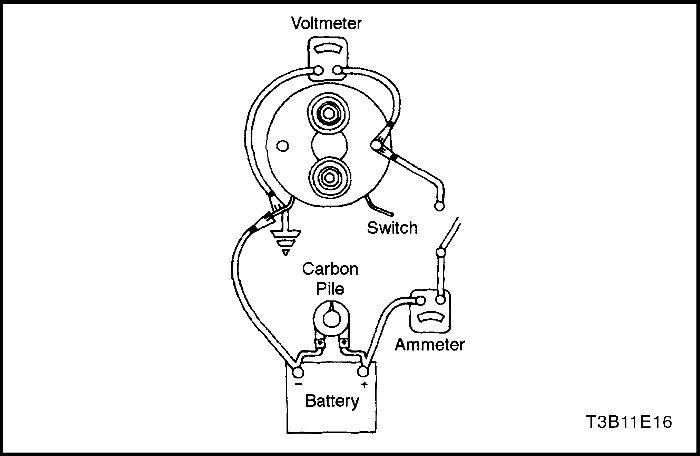
- Test the solenoid windings by checking the current draw.
- Check the hold-in windings by connecting an ammeter in series with a 12-volt battery, the switch terminal, and to ground.
- Connect the carbon pile across the battery.
- Adjust the voltage to 10 volts. The ammeter reading should be 13 to 19 amperes.Current will decrease as the windings heat up. Current draw readings that are over specifications indicate shorted turns or a ground in the windings of the solenoid. Both conditions require replacement of the solenoid. Current draw readings that are under specifications indicate excessive resistance. No reading indicates an open circuit.
Important : Current will decrease as the windings heat up. Current draw readings that are over specifications indicate shorted turns or a ground in the windings of the solenoid. Both conditions require replacement of the solenoid. Current draw readings that are under specifications indicate excessive resistance. No reading indicates an open circuit.
- Check both windings, connecting them according to the preceding test.
- Ground the solenoid motor terminal.
- Adjust the voltage to 10 volts. The ammeter reading should be 59 to 79 amperes.
- Check the connections and replace the solenoid, if necessary.
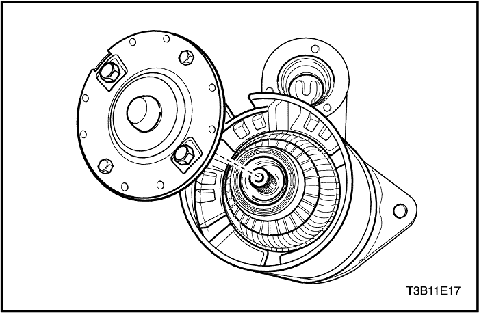
- Slide the field frame with enclosed armature assembly away from the starter assembly.
- Remove the shield.
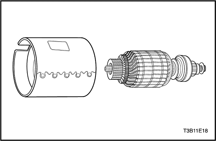
- Separate the field frame from the armature.
- Inspect the shaft and the pinion for discoloration, damage, or wear. Replace, if necessary.
- Inspect the armature commutator. If the commutator is rough, it should be turned down. The outside diameter of the commutator must measure at least 26.9 - 27.1mm (1.059 - 1.067 in.) after it is undercut or turned. Do not turn out-of-round commutators.
- Inspect the points where the armature conductors join the commutator bars. Make sure they have a good connection. A burned commutator bar is usually evidence of a poor connection.
- If test equipment is available, check the armature for short circuits by placing it on a growler, and holding back a saw blade over the armature core while the armature is rotated. If the saw blade vibrates, replace the armature.
- Recheck the armature after cleaning between the commutator bars. If the saw blade vibrates, replace the armature.
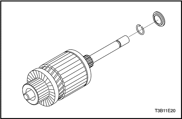
- Remove the locking ring from the groove in the driveshaft.
- Remove the pinion stop and the drive from the driveshaft.
- If not done in the previous steps, remove the screws that hold the solenoid assembly into the housing, and remove the nut from the field coil connector.
- Rotate the solenoid 90 degrees and remove it along with the return spring.
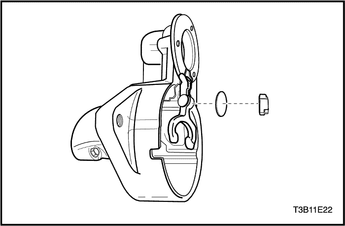
- Remove the plunger with the boot and the shift lever assembly. Test the solenoid windings, if not done in Step 11.
Important : The pinion clearance must be correct to prevent the buttons on the shift lever yoke from rubbing on the clutch collar during the cranking.
- When the starter motor is disassembled and the solenoid is replaced, it is necessary to check the pinion clearance.
- Disconnect the motor field coil connector from the solenoid motor terminal and carefully insulate the connector.
- Connect one 12-volt battery lead to the solenoid switch terminal and the other to the starter frame.
- Flash a jumper lead momentarily from the solenoid motor terminal to the starter frame, allowing shifting of the pinion in the cranking position, where it will remain until the battery is disconnected.
Important : A means for adjusting the pinion clearance is not provided on the starter motor. If the clearance does not fall within the limits, check for improper installation and replace all worn parts.
- Push the pinion back as far as possible to take up any movement, and check the clearance with a feeler gauge. The clearance should be 0.25 to 3.56 mm (0.01 to 0.14 inch).
Assembly Procedure
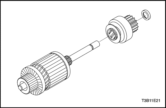
- Install the drive and the pinion stop on the driveshaft.
- Install the lock ring into the groove on the driveshaft and insert the collar.
- Install the shift lever, washer and the cushion.
- Lubricate the drive end of the armature shaft with lubricant.
- Position the solenoid assembly.
- Fasten the solenoid assembly with the screws.
Tighten
Tighten the starter solenoid assembly screws to 8 N•m (71 lb-in).
- Install the field coil connection to the starter terminal. Install the nut.
Tighten
Tighten the starter field coil connector nut to 8 N•m (71 lb-in).
- Position the armature assembly into the field frame.
- Place the shield on the armature and field frame assembly.
- Install the armature and field frame assembly with the shield into the starter housing.
- Position the commutator end frame/brush holder assembly, lining up the end frame holes with the through-bolt holes in the housing.
- Install the starter through-bolts.
- Install the starter. Refer to "Starter"in this section.
Tighten
Tighten the starter through-bolts to 6 N•m (53 lb-in).
Generator (1.2 SOHC)
Disassembly Procedure
- Remove the generator. Refer to "Generator"in this section.
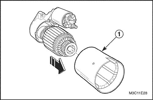
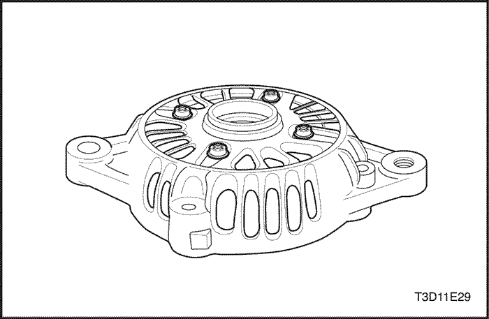
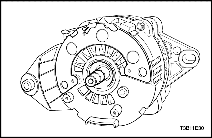
- Remove the front bracket and rear bracket.
- Remove the through-bolts (1).
- Pry front bracket downwards using a screwdriver (2).
- Separate the front bracket and rear bracket (3).
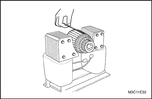
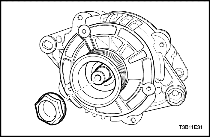
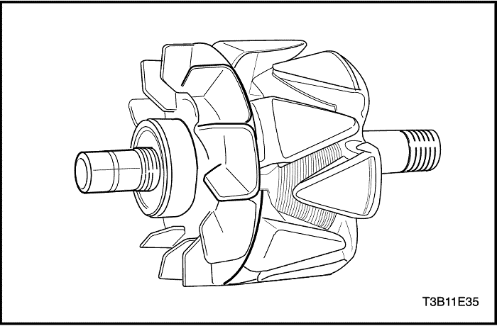
- Remove the pulley and rotor assembly from the front bracket.
- Cover the rotor with the cloth (1).
- Place the pulley upwards and vice the rotor (2).
- Remove the pulley nut (3).
- Remove the pulley (4).
- Remove the front bracket, rotor and collar.
- Remove the collar (large) (1).
- Remove the rotor from the front bracket (2).
- Remove the collar (small) from the rotor shaft (3).
- Remove the front bearing.
- Remove the support plate screws (1).
- Remove the plate (2).
- Remove the front bearing using the press (3).
- Remove the battery positive terminal nut from the rear bracket.
- Remove the battery position terminal nut (1).
- Remove the washer (2).
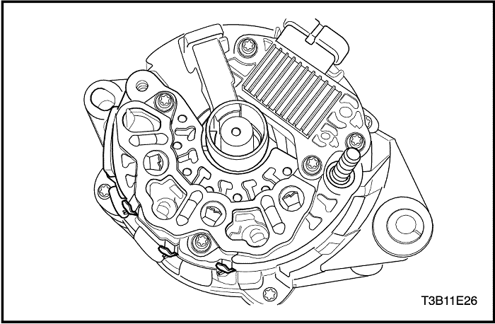
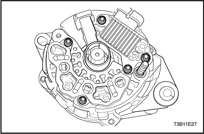
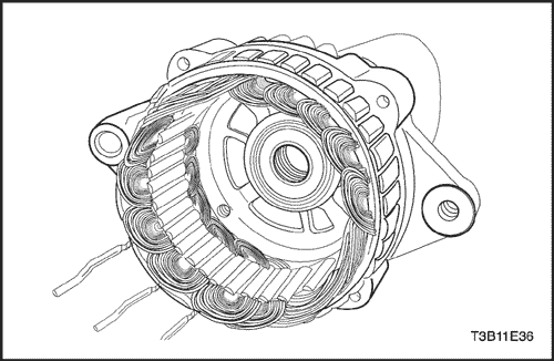
- Remove the stator assembly from the rear bracket.
- Remove the rectifier screw (1).
- Remove the brush holder and regulator assembly screws (2).
- Remove the stator assembly with the rectifier / brush holder / regulator (3).
- Remove the rectifier / brush holder / regulator from the stator.
- Remove the rectifier / brush holder / regulator connections (1).
- Remove the stator and rectifier connections (2).
Notice : If the stator connections are welded, melt the lead. Avoid overheating as it can damage the diodes.
Inspection / Measurement
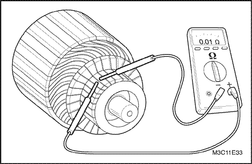
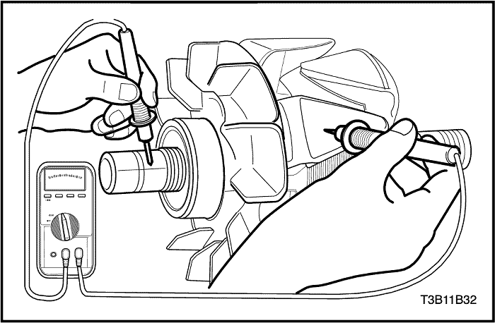
- Inspect the rotor assembly.
- Test the rotor for an open circuit by using the ohmmeter (1). Replace the rotor if necessary.
- Test the rotor for open or short circuit (2).
Desciption | Limit |
The measured resistance | 2.9 Ω |
- Replace the rotor if necessary.
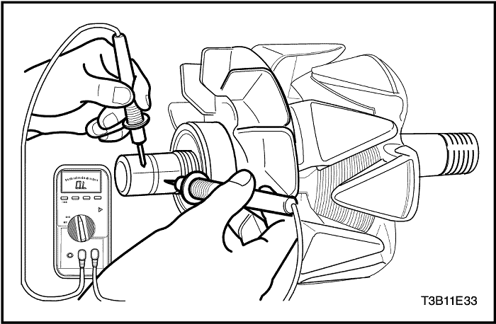
- Test the rotor for open or ground circuit by using the ohmmeter (3). Replace the rotor if necessary.
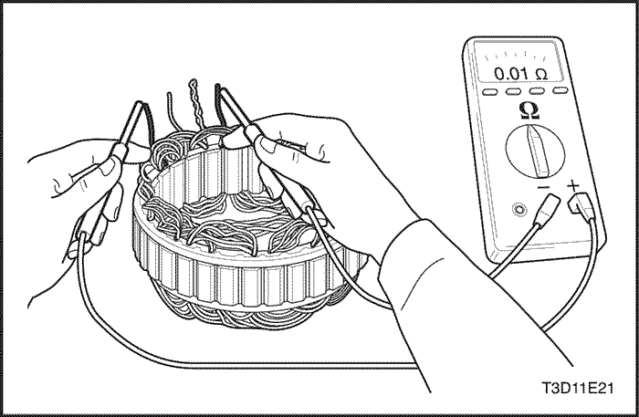
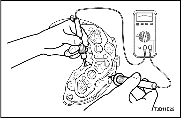
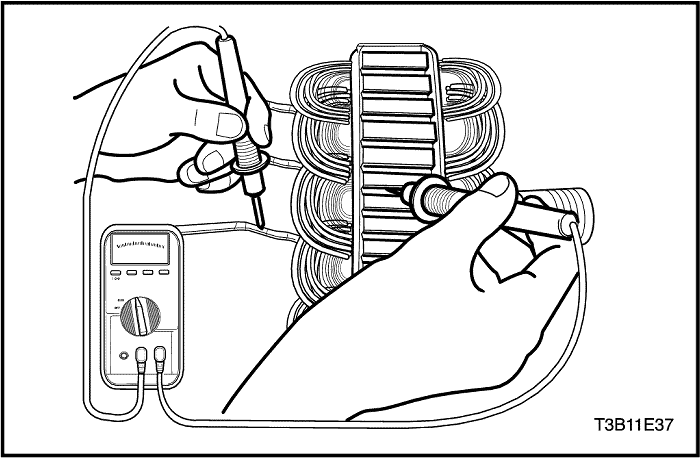
- Inspect the stator.
- Test the stator for an open circuit by using the ohmmeter (1). Replace the stator if necessary.
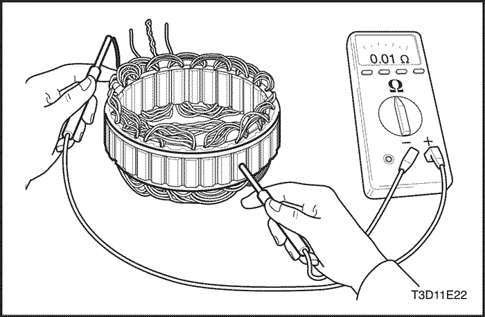
- Test the stator for open or ground circuit by using the ohmmeter (2). Replace the starter if necessary.
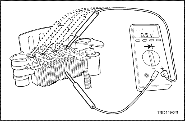
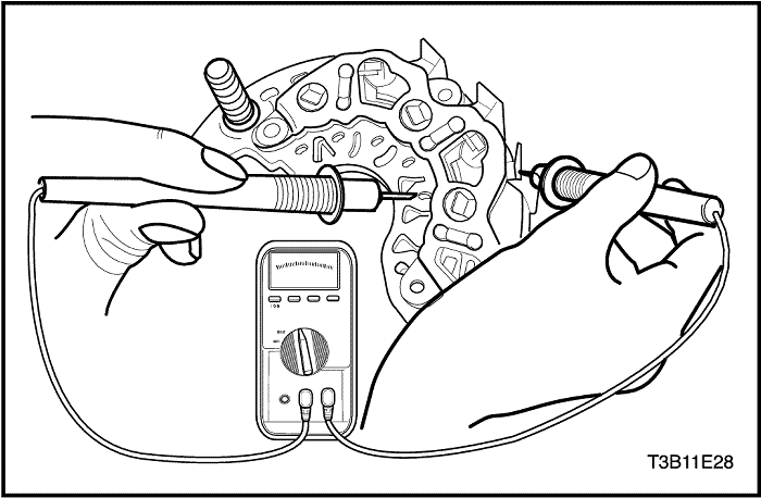
- Inspect the rectifier.
- Inspect the open circuit for stator coil lead terminals using the ohmmeter (1).
- Replace the rectifier if necessary.
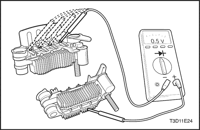
- Inspect the open circuit for stator coil lead terminals using the ohmmeter (2).
- Replace the rectifier if necessary.
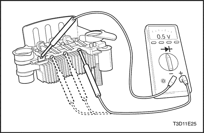
- Inspect trio diodes.
- Inspect the open circuit for trio diodes using the ohmmeter (1).
- Replace the heat sink if necessary (a).
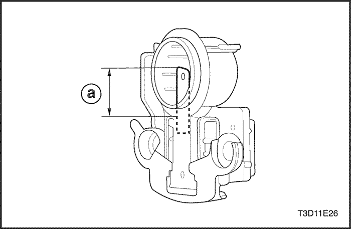
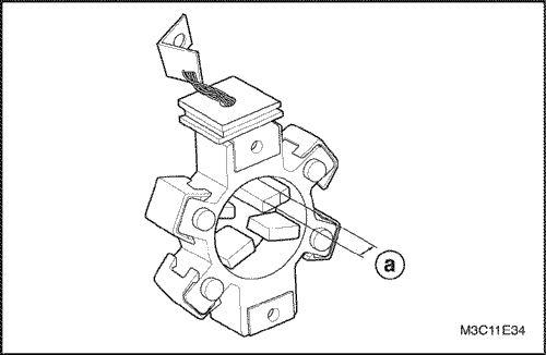
- Inspect the brush wear.
- If the brush wear exceeds the specified valve (a), replace the brush.
Desciption | Standard | Limit |
Brushes wear | 18.5 (0.73) | 13.5 (0.53) |
Assembly Procedure
- Install in the reverse order of removal.
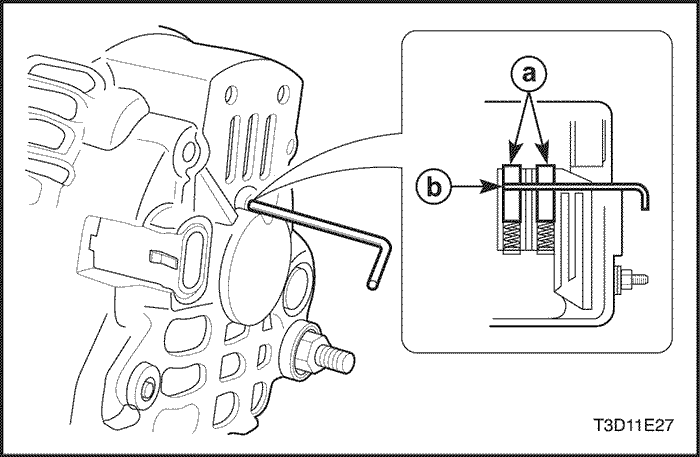
- Assemble the stator assembly into the rear bracket and rotor assembly.
- a. Brushes
- b. Hole
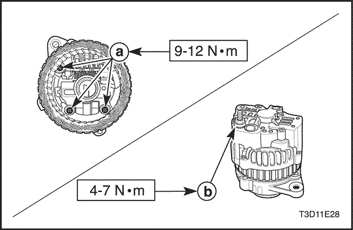
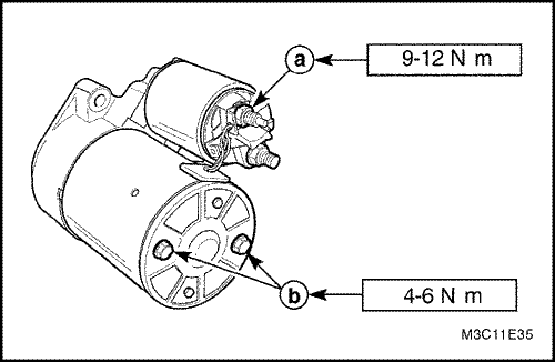
- Install the bolts/nuts/screws.
Tighten
- Tighten the brush holder/regulator/rectifier screws to 9-12 N•m (80-106 lb-in) (a).
- Tighten the battery positive terminal nut to 4-7 N•m (35-62 lb-in) (b).
- Tighten the front bearing spot plate screws to 6-8 N•m (53-71 lb-in) (c).
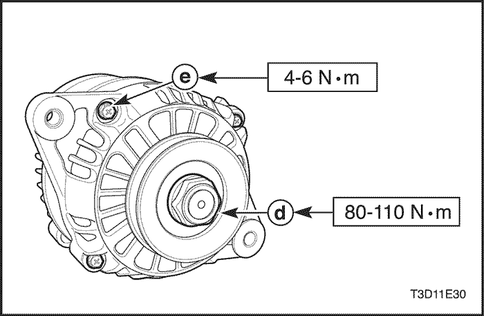
- Tighten the generator pulley nut to 80-110 N•m (59-81 lb-ft) (d).
- Tighten the through-bolts to 4-6 N•m (35-53 lb-in) (e).
Generator (1.4 DOHC)
Disassembly Procedure
- Remove the generator. Refer to "Generator"in the On-Vehicle Service section.
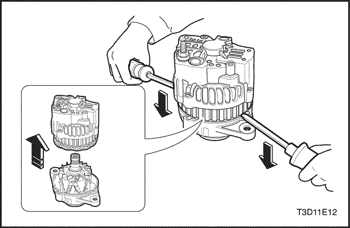
- Mark a match line that cannot easily be removed on the end frame to make assembly easier.
- Pry off the plastic cover to expose the stator connections.
Notice : If the stator connections are not welded, melt the lead. Avoid excessive heating, as it can damage the diodes in the rectifier bridge.
- Remove the stator connections from the rectifier bridge terminals by cutting the wires.
- Pry off the baffle.
- Remove the rectifier/regulator/brush holder assembly screws.
- Remove the brush holder assembly and the regulator.
Important : If the brush can be reused, reassmble the brush to the holder with the retaining pin, after cleaning the brush with a soft, clean cloth.
- Test the rectifier bridge by connecting the ohmmeter terminals to the brdge and the heat sink.
- Retest by connecting the ohmmeter terminals in reverse.
- Replace the rectifier bridge, if each reading is the same.
- Test the remaining two diodes after the above procedure.
Notice : Some kinds of digital ohmmeters are not suited for the test of the bridge diode. In this case, consult the manufacturer regarding the test capacity.
- Test the diodes by connecting the ohmmeter terminals to the bridge terminal and the base plate. If the reading is the same, the rectifier bridge should be replaced.
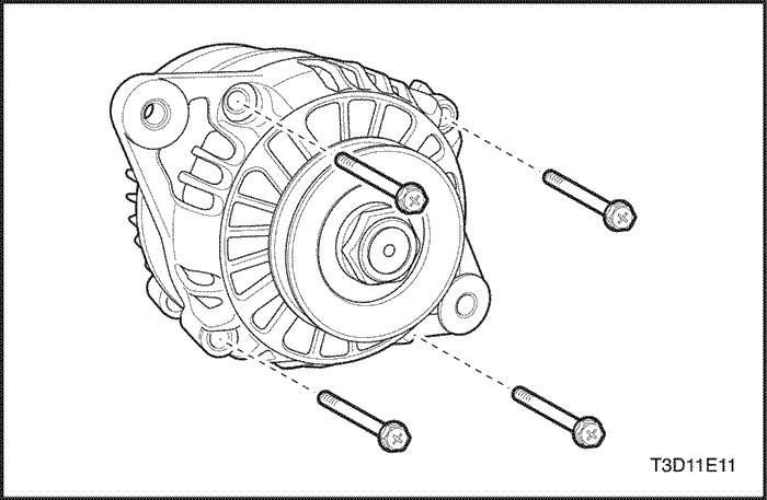
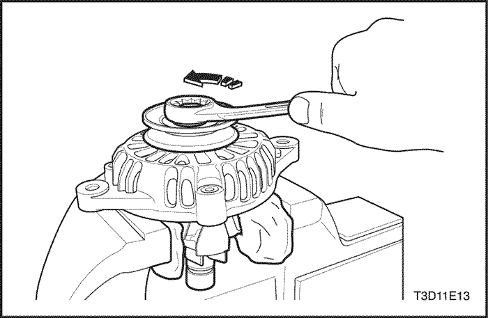
- Remove the generator through - bolts.
Important : The fastening torque of this nut is 81 N•m (60 lb-ft) and may not normally be unfastened using hand strength.
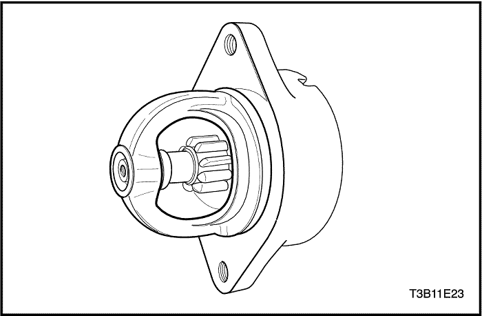
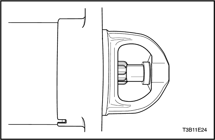
- Move to the drive end of the generator and remove the drive end bearing nut.
- Remove the pulley and the collars.
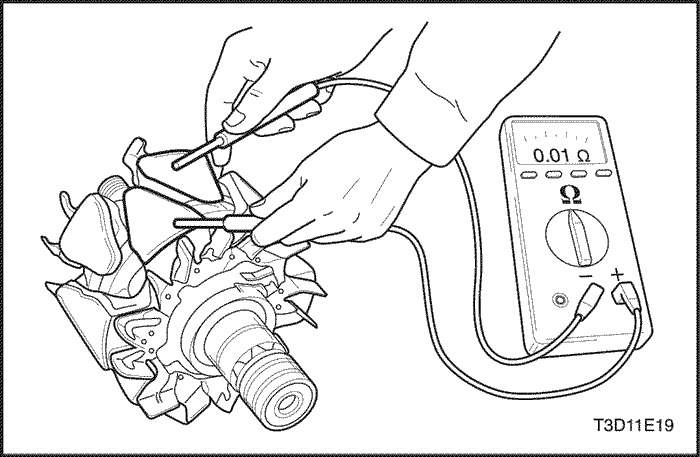
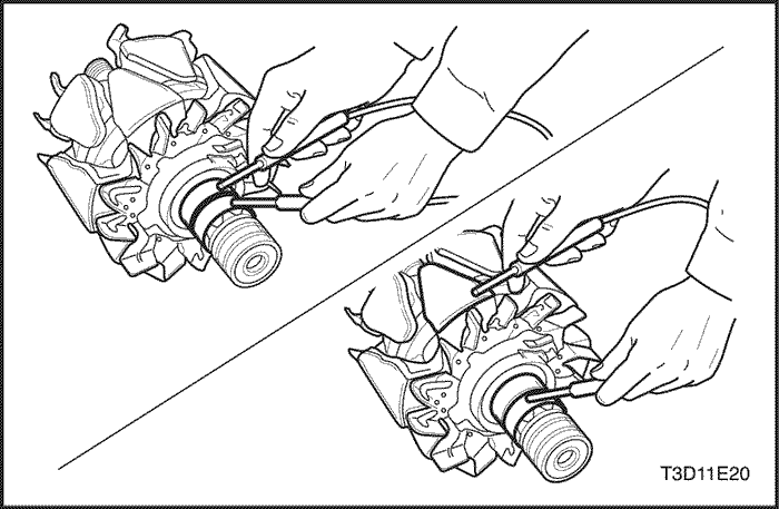
- Test the rotor for an open circuit using the ohmmeter with the drive end frame assembled. The reading should be sufficiently high, or the rotor must be replaced.
- Test the rotor for open and short circuits. The reading should be 1.7 to 2.3 ohms, or the rotor should be replaced.
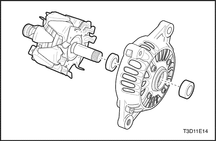
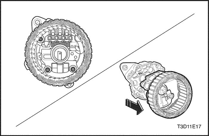
- Remove the drive end frame from the shaft.
- For vehicles with an internal generator fan, remove the drive end frame and the fan.
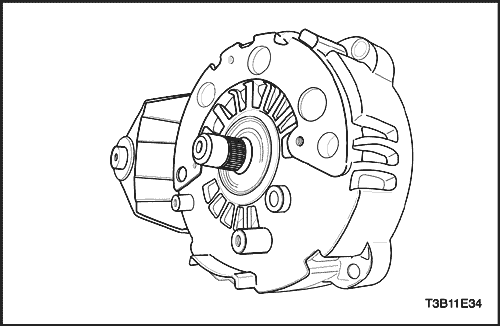
- Remove the rotor assembly.
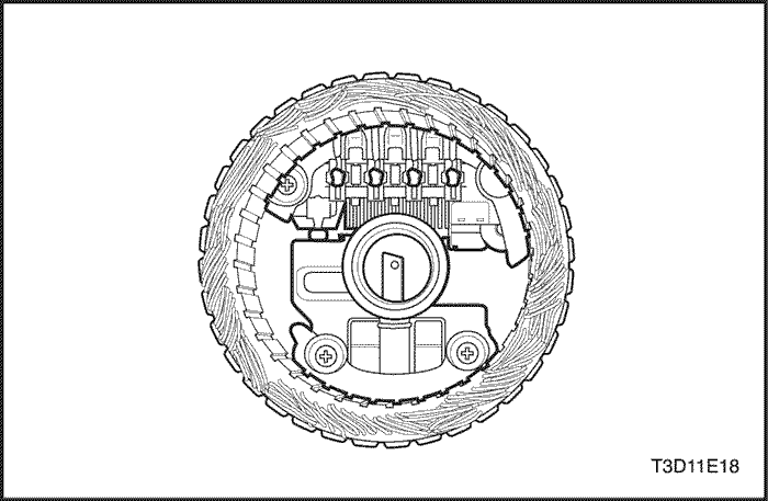
- Remove the stator.
- Test the stator for an open circuit using the ohmmeter.
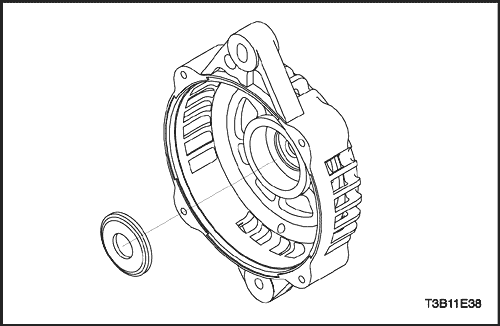
- Remove the ring in the slip ring end frame.
Assembly Procedure
- Install the new ring in the slip ring end frame.
- Install the stator.
- Position the rotor assembly shaft with the drive end frame in the slip ring end assembly until the gap between the outer lace and the end frame casting is 1.9 mm (0.075 inch).
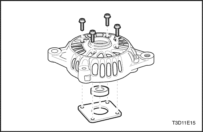
- Install the generator through-bolts.
Tighten
Tighten the generator through-bolts to 10 N•m (89 lb-in).
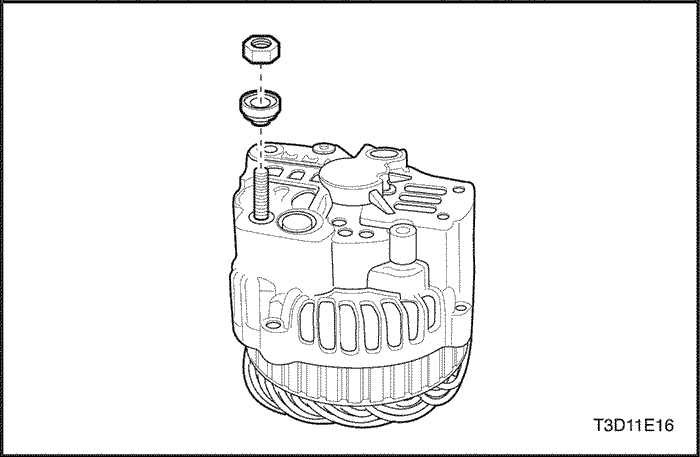
- Position the fan, the collars, and the pulley on the rotor shaft and secure with the nut.
Tighten
Tighten the generator drive end bearing nut to 81 N•m (60 lb-ft).
- Install the generator. Refer to "Generator"in the On-Vehicle Service section.
- Weld the brush holder terminal to the regulator terminal, if removed.
- Fix the brush holder with the retainer pin, and weld the regulator/brush holder assembled terminal to the rectifier terminal.
- Apply silicone grease between the bridge and the end frame for radiation purposes.
- Fasten the screws holding the rectifier regulator/brush holder assembly to the end frame.
- Punch the new baffle with the pin into the brush.
Notice : Take care to prevent damage to the vehicle by protecting the diode in the rectifier bridge from excessive heat while welding.
- Weld the connectors of the rectifier bridge.
GENERAL DESCRIPTION AND SYSTEM OPERATION
Battery
The battery has three major functions in the electrical system. First, the battery provides a source of energy for cranking the engine. Second, the battery acts as a voltage stabilizer for the electrical system. Finally, the battery can, for a limited time, provide energy when the electrical demand exceeds the output of the generator.
The sealed battery is standard on all cars. There are no vent plugs in the cover. The battery is completely sealed, except for two small vent holes in the sides. These vent holes allow the small amount of gas produced in the battery to escape.
The sealed battery has the following advantages over conventional batteries:
- No water need be added for the life of the battery.
- It is protected against overcharge. If too much voltage is applied to the battery, it will not accept as much current as a conventional battery. In a conventional battery, the excess voltage will still try to charge the battery, leading to gassing, which causes liquid loss.
- It is not as liable to self-discharge as a conventional battery. This is particularly important when a battery is left standing for long periods of time.
- It has more power available in a lighter and a smaller case.
Ratings
A battery has two ratings: (1) a reserve capacity rating designated at 27°C (80°F), which is the time a fully charged battery will provide 25 amperes current flow at or above 10.5 volts; (2) A cold cranking amp rating determined under testing at -18°C (0°F), which indicates the cranking load capacity.
Reserve Capacity
The reserve capacity is the maximum length of time it is possible to travel at night with the minimum electrical load and no generator output. Expressed in minutes, Reserve Capacity (or RC rating) is the time required for a fully charged battery, at a temperature of 27°C (81°F) and being discharged at a current of 25 amperes, to reach a terminal voltage of 10.5 volts.
Cold Cranking Amperage
The cold cranking amperage test is expressed at a battery temperature of -18°C (0°F). The current rating is the minimum amperage, which must be maintained by the battery for 30 seconds at the specified temperature, while meeting a minimum voltage requirement of 7.2 volts. This rating is a measure of cold cranking capacity.
The battery is not designed to last indefinitely. However, with proper care, the battery will provide many years of service.
If the battery tests well, but fails to perform satisfactorily in service for no apparent reason, the following factors may point to the cause of the trouble:
- Vehicle accessories are left on overnight.
- Slow average driving speeds are used for short periods.
- The vehicle’s electrical load is more than the generator output, particularly with the addition of aftermarket equipment.
- There are defects in the charging system, such as electrical shorts, a slipping generator belt, a faulty generator, or a faulty voltage regulator.
- There has been battery abuse, including failure to keep the battery cable terminals clean and tight, or a loose battery hold-down.
- There are mechanical problems in the electrical system, such as shorted or pinched wires.
Built - In Hydrometer
The sealed battery has a built-in, temperature-compensated hydrometer in the top of the battery. This hydrometer is to be used with the following diagnostic procedure:
- When observing the hydrometer, make sure that the battery has a clean top.
- Under normal operation, two indications can be observed:
- GREEN DOT VISIBLE - Any green appearance is interpreted as a "green dot," meaning the battery is ready for testing.
- DARK GREEN DOT IS NOT VISIBLE - If there is a cranking complaint, the battery should be tested. The charging and electrical systems should also be checked at this time.
- Occasionally, a third condition may appear:
- Occasionally, a third condition may appear:
- CLEAR OR BRIGHT YELLOW - This means the fluid level is below the bottom of the hydrometer. This may have been caused by excessive or prolonged charging, a broken case, excessive tipping, or normal battery wear. Finding a battery in this condition may indicate high charging by a faulty charging system. Therefore, the charging and the electrical systems may need to be checked if a cranking complaint exists. If the cranking complaint is caused by the battery, replace the battery.
Charging Procedure
- Batteries with the green dot showing do not require charging unless they have just been discharged, such as in cranking a vehicle.
- When charging sealed-terminal batteries out of the vehicle, install the adapter kit. Make sure all the charger connections are clean and tight. For best results, batteries should be charged while the electrolyte and the plates are at room temperature. A battery that is extremely cold may not accept current for several hours after starting the charger.
- Charge the battery until the green dot appears. The battery should be checked every half-hour while charging. Tipping or shaking the battery may be necessary to make the green dot appear.
- After charging, the battery should be load tested. Refer to "Starter Motor" in this section.
Charging Time Required
The time required to charge a battery will vary depending upon the following factors:
- Size of Battery - A completely discharged large heavy-duty battery requires more than twice the recharging as a completely discharged small passenger car battery.
- Temperature - A longer time will be needed to charge any battery at -18°C (0°F) than at 27°C (81°F). When a fast charger is connected to a cold battery, the current accepted by the battery will be very low at first. The battery will accept a higher current rate as the battery warms.
- Charger Capacity - A charger which can supply only 5 amperes will require a much longer charging period than a charger that can supply 30 amperes or more.
- State-of-Charge - A completely discharged battery requires more than twice as much charge as a onehalf charged battery. Because the electrolyte is nearly pure water and a poor conductor in a completely discharged battery, the current accepted by the battery is very low at first. Later, as the charging current causes the electrolyte acid content to increase, the charging current will likewise increase.
Charging A Completely Discharged Battery (Off The Vehicle)
Unless this procedure is properly followed, a perfectly good battery may be needlessly replaced.
The following procedure should be used to recharge a completely discharged battery:
- Measure the voltage at the battery terminals with an accurate voltmeter. If the reading is below 10 volts, the charge current will be very low, and it could take some time before the battery accepts the current in excess of a few milliamperes. Refer to "Charging Time Required" in this section, which focuses on the factors affecting both the charging time required and the rough estimates in the table below. Such low current may not be detectable on ammeters available in the field.
- Set the battery charger on the high setting.
Important : Some chargers feature polarity protection circuitry, which prevents charging unless the charger leads are correctly connected to the battery terminals. A completely discharged battery may not have enough voltage to activate this circuitry, even though the leads are connected properly, making it appear that the battery will not accept charging current. Therefore, follow the specific charger manufacturer’s instruction for bypassing or overriding the circuitry so that the charger will turn on and charge a low-voltage battery.
- Battery chargers vary in the amount of voltage and current provided. The time required for the battery to accept a measurable charger current at various voltages may be as follows:
- Battery chargers vary in the amount of voltage and current provided. The time required for the battery to accept a measurable charger current at various voltages may be as follows:
Voltage | Hours |
16.0 or more | Up to 4 hours |
14.0-15.9 | Up to 8 hours |
13.9 or less | Up to 16 hours |
- If the charge current is not measurable at the end of the above charging times, the battery should be replaced.
- If the charge current is measurable during the charging time, the battery is good, and charging should be completed in the normal manner.
Important : It is important to remember that a completelydischarged battery must be recharged for a sufficient number of ampere hours (AH) to restore the battery to a usable state. As a general rule, using the reserve capacity (RC) rating as the number of ampere hours of charge usually brings the green dot into view.
- If the charge current is still not measurable after using the charging time calculated by the above method, the battery should be replaced.
- If the charge current is measurable during the charging time, the battery is good, and charging should be completed in the normal manner.
Jump Starting Procedure
- Position the vehicle with the good(charged) battery so that the jumper cables will reach from the one battery to the other.
- Turn off the ignition, all the lights, and all the electrical loads in both vehicles. Turn on the hazard flashers if jump starting where there is traffic. In addition, turn on any other lights needed for the work area.
- In both vehicles, apply the parking brake firmly.
Notice : Make sure the cables are not on or near pulleys, fans, or other parts that will move when the engine starts, damaging the parts.
- Shift an automatic transaxle to PARK, or a manual transaxle to NEUTRAL.
- Shift an automatic transaxle to PARK, or a manual transaxle to NEUTRAL.
Caution : Do not use cables that have loose or missing insulation, or injury could result.
- Clamp one end of the first jumper cable to the positive terminal on the battery. Make sure it does not touch any other metal parts. Clamp the other end of the same cable to the positive terminal on the other battery. Never connect the other end to the negative terminal of the discharged battery.
- Clamp one end of the first jumper cable to the positive terminal on the battery. Make sure it does not touch any other metal parts. Clamp the other end of the same cable to the positive terminal on the other battery. Never connect the other end to the negative terminal of the discharged battery.
Caution : Do not attach the cable directly to the negative terminal of the discharged battery. Doing so could cause sparks and possible battery explosion.
- Clamp one end of the second cable to the negative terminal of the booster battery. Make the final connection to a solid engine ground, such as the engine lift bracket, at least 450 millimeters (18 inches) from the discharged battery.
- Clamp one end of the second cable to the negative terminal of the booster battery. Make the final connection to a solid engine ground, such as the engine lift bracket, at least 450 millimeters (18 inches) from the discharged battery.
- Start the engine of the vehicle with the good battery. Run the engine at a moderate speed for several minutes. Then start the engine of the vehicle which has the discharged battery.
- Remove the jumper cables by reversing the above sequence exactly. Remove the negative cable from the vehicle with the discharged battery first. While removing each clamp, take care that it does not touch any other metal while the other end remains attached.
Generator
The KDAC charging system has several models available, including the Ø114D (Valeo Mando) or CS121D. The number denotes the outer diameter in millimeters of the stator lamination.
CS generators are equipped with internal regulators. The Y connection (Valeo Mando) or Delta (KDAC) stator, a rectifier bridge, and a rotor with slip rings and brushes are electrically similar to earlier generators. A conventional pulley and fan are used. There is no test hole.
Unlike three-wire generators, the Ø114D (Valeo Mando) or CS121D (KDAC) may be used with only two connections: battery positive and an "L" terminal to the charge indicator lamp.
As with other charging systems, the charge indicator lamp lights when the ignition switch is turned to ON, and goes out when the engine is running. If the charge indicator is on with the engine running, a charging system defect is indicated.
The regulator voltage setting varies with temperature and limits the system voltage by controlling the rotor field current. The regulator switches rotor field current on and off. By varying the on-off time, correct average field current for proper system voltage control is obtained. At high speeds, the on-time may be 10 percent and the off-time 90 percent. At low speeds, with high electrical loads, on-time may be 90 percent and the off-time 10 percent.
The mono regulator having 2~3 pins in the terminal can be applied for generator. The regulator maintains the system voltage by controlling field current on-off without typically fixed freguency.
Charging System
The KDAC charging system has several models available, including the Ø114D (Valeo Mando) or CS121D. The number denotes the outer diameter in millimeters of the stator laminations.
CS generators use a new type of regulator that incorporates a diode trio. The Y connection (Valeo Mando) or Delta KDAC stator, a rectifier bridge, and a rotor with slip rings and brushes are electrically similar to earlier generators. A conventional pulley and fan are used. There is no test hole.
Starter
Wound field starter motors have pole pieces, arranged around the armature, which are energized by wound field coils.
Enclosed shift lever cranking motors have the shift lever mechanism and the solenoid plunger enclosed in the drive housing, protecting them from exposure to dirt, icy conditions, and splashes.
In the basic circuit, solenoid windings are energized when the switch is closed. The resulting plunger and shift lever movement causes the pinion to engage the engine flywheel ring gear. The solenoid main contacts close. Cranking then takes place.
When the engine starts, pinion overrun protects the armature from excessive speed until the switch is opened, at which time the return spring causes the pinion to disengage. To prevent excessive overrun, the switch should be released immediately after the engine starts.
Starting System
The engine electrical system includes the battery, the ignition, the starter, the generator, and all the related wiring. Diagnostic tables will aid in troubleshooting system faults. When a fault is traced to a particular component, refer to that component section of the service manual.
The starting system circuit consists of the battery, the starter motor, the ignition switch, and all the related electrical wiring. All of these components are connected electrically.


