SECTION 2E
TIRES AND WHEELS
SPECIFICATIONS
Tire Size and Pressure Specifications
Inflation Pressure at Full Load
Tire | Wheel | Front | Rear |
. | . | kPa | psi | kPa | psi |
155/80R13 | 13 x 5.0J (Steel) | 207 | 30 | 207 | 30 |
185/60R14 | 14 x 5.5J (Alloy/Steel) | ↑ | ↑ | ↑ | ↑ |
185/55R15 | 15 x 6.0J (Alloy/Steel) | ↑ | ↑ | ↑ | ↑ |
Inflation Pressure Conversion Pecifications
kPa | kPa | kPa | psi | kPa | psi |
140 | 20 | 185 | 27 | 235 | 34 |
145 | 21 | 190 | 28 | 240 | 35 |
155 | 22 | 200 | 29 | 250 | 36 |
160 | 23 | 205 | 30 | 275 | 40 |
165 | 24 | 215 | 31 | 310 | 45 |
170 | 25 | 220 | 32 | 345 | 50 |
180 | 26 | 230 | 33 | 380 | 55 |
Fastener Tightening Specifications
Application | N•m | Lb-Ft | Lb-In |
Wheel Nut (Aluminum Wheel) | 120 | 88 | - |
Wheel Nut (Steel Wheel) | 120 | 88 | - |
DIAGNOSIS
Wheel Runout
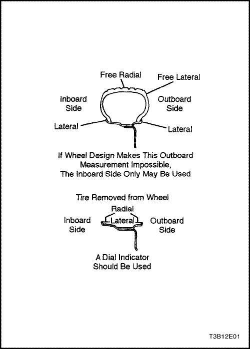
Measure wheel runout with an accurate dial indicator.Measurements may be taken with the wheels either onor off the vehicle, using an accurate mounting surfacesuch as a wheel balancer. Measurements may be takenwith or without the tire mounted on the wheel.
Measure radial runout and lateral runout on both the inboardand the outboard rim flanges. With the dial indicatorfirmly seated next to the wheel and tire assembly,slowly rotate the wheel one revolution and record the indicatorreading. If any measurement exceeds the followingspecifications and there is a vibration that wheelbalancing will not correct, replace the wheel. Disregardany indicator readings due to welds, paint runs, orscratches.
Steel Wheels
- Radial runout: 0.8 mm (0.03 inch)
- Lateral runout: 1.0 mm (0.04 inch)
Aluminum Wheels
- Radial runout: 0.8 mm (0.03 inch)
- Lateral runout: 0.8 mm (0.03 inch)
Measure free radial runout on the center of the tire tread.The tread can be taped to present a smooth surface.Measure free lateral runout on the outboard side of thetire nearest to the tread.
Steel and Aluminum Wheels
- Free radial runout: 1.5 mm (0.06 inch)
- Free lateral runout: 1.5 mm (0.06 inch)


MAINTENANCE AND REPAIR
ON-VEHICLE SERVICE
Wheel
Removal Procedure
- Loosen the wheel nuts.
- Raise and suitably support the vehicle.
- Remove the wheel nuts.
Notice : Never use heat to loosen a tight wheel. It canshorten the life of the wheel, the wheel nuts and thewheel bearings. Excessive force, such as hammeringthe wheel or tire, can also cause damage and is not recommended.Slight tapping of the wheel sidewall withone's hand or with a rubber mallet is acceptable.
- Remove the wheel.
Difficulty in removing the wheels from the vehicle can bedue to foreign material or to a tight fit between the wheelcenterhole and the hub or the rotor. These wheels canbe removed by
- Retightening the wheel nuts on the affected wheeland then loosening the wheel nuts by two turns.
- Lowering the vehicle and rocking it from side to sideas hard as possible, using one or more person’s bodyweight to loosen the wheel.
- Raising the vehicle and removing the wheel.
Caution : Do not allow the penetrating oil to get onthe vertical surfaces between the wheel and thedrum (or rotor) because penetrating oil in this areacould cause the wheel to work loose as the vehicleis driven, resulting in loss of control and an injuryaccident.
Penetrating oil is not effective in removing tight wheels.If it is used, however, apply it sparingly and only to thewheel’s centerhole area.
Installation Procedure
Notice : Before installing the wheels, remove any buildupof corrosion on the wheel mounting surface and thebrake drum or the rotor mounting surface by scrapingand brushing them with a wire brush. Installing thewheels without good metal-to-metal contact at themounting surfaces can cause the wheel nuts to loosen,which can later allow a wheel to come off while the vehicleis moving. Wheel nuts must be tightened in sequenceand to the proper torque to avoid bending thewheel, the brake drum or the rotor.
- Mount the wheel.
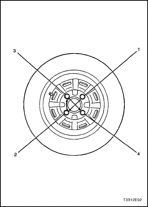
- Install the wheel nuts and tighten the wheel nuts in the sequence shown.
- Lower the vehicle.
Tighten
Tighten the wheel nuts to 120 N•m (88 lb-ft).
On-Vehicle Balancing
On-vehicle balancing will help correct vibrations due tobrake drum, rotor, and wheel cover imbalances.
Notice : Do not allow the front suspension to hang free.When the drive axle is run at an extreme angle, extravibrations can occur, as well as damage to seals andjoints.
- During on-vehicle balancing, do not remove the balanceweights from the off-vehicle dynamic balance.
- If more than 1 ounce of additional weight is required,split the weight between the inner and the outer rimflanges.
Caution : Do not spin the drive wheels faster than55km/h (35 mph) as indicated by the speedometer.This limit is necessary because the speedometer indicatesonly one-half of the actual wheel speedwhen one drive wheel is spinning and the otherdrive wheel is stopped. Personal injury and damagemay result from high-speed spinning.
- Spin the driven tire and wheel assemblies using theengine.
UNIT REPAIR
Aluminum Wheel Porosity
Wheel repairs that use welding, heating or peening arenot approved.
- Raise and suitably support the vehicle.
- Remove the tire and wheel assembly. Refer to "Wheel"in this section.
Caution : To avoid serious injury, do not stand overthe tire when inflating, because the bead may breakwhen it snaps over the safety hump. Do not exceed275 kPa (40 psi) of air pressure in any tire if thebeads are not seated. If 275 kPa (40 psi) of air pressurewill not seat the beads, deflate the tire. Relubricatethe beads. Reinflate the tire. Overinflation maycause the bead to break and cause serious injury.
- Locate leaking areas by inflating the tire to 345 kPa(50 psi) and dipping the tire and wheel assembly intoa water bath.
- Mark the leak areas and remove the tire from thewheel.
- Scuff the inside wheel surface at the leak area with80-grit sandpaper. Clean the leak area with a general-purposecleaner.
- Apply a 3.3 mm (0.13 inch) thick layer of adhesive/sealant to the leak area. Allow it to dry for 12 hours.
- Install the tire on the wheel. Inflate the tire to 345 kPa(50 psi) and check for leaks as in step 3.
- Adjust the tire pressure to meet specifications. Referto "Tire Size and Pressure Specifications"in this section.
Install the tire and wheel assembly. Refer to
"Wheel"in this section.
Lower the vehicle.
Aluminum Wheel Refinishing
A protective clear or color coating is applied to the surfaceof the original equipment cast aluminum wheels.Surface degradation can develop if this clear coating isdamaged or removed. This can happen at some automaticcar wash facilities that use silicone carbide-tippedtire brushes to clean white walls and tires. Once the protectivecoating is damaged, exposure to caustic cleanersor road salt causes further surface degradation. Thefollowing procedure details how to strip, clean and recoataluminum wheels.
Caution : Follow the manufacturer's recommendationsand cautions when using these materials.
Required materials:
Amchem Alumi Prep No. 23, stock No. DX533 or equivalentcleaning and conditioning chemical for aluminum.
Amchem Alodine No. 101, stock No. DX50T or equivalentcoating chemical for aluminum.
Ditzler Delclear Acrylic Urethane Clear, Stock No.DAU-75 or equivalent.
Ditzler Delthane Ultra-Urethane Additive, StockDXR-80 or equivalent.
Before repairing the aluminum damage or the clear coatdamage, prepare the wheels and the tires.
- Remove the wheel from the vehicle.
- Mark the location of the outboard weights and removethem.
- Wash the wheel inside and out with a water-based,all-purpose cleaner. Remove the grease and oil with asolvent cleaner.
- Mask the tire prior to painting.
- Using a 400-grit wet or dry sandpaper, sand over thepainted areas that will not require recoloring. Sandingwill promote the adhesion of the clear coat.
Aluminum Damage on Wheel Surface
- Mount the wheel on a brake lathe and spin the assemblyslowly.
Sand the wheel with a backing block or pad. Hold thebacking block or pad flat to the surface of the wheeland sand slowly back and forth from the center to theouter edge of the tire to remove the damage. Use thefollowing sandpaper grits in the order listed:
- 80 grit.
- 150 grit.
- 240 grit.
Clear Coat Damage on Unpainted Wheels
- Apply the chemical stripper Amchem Alumi Prep No.23. Use a small 1/4-inch detail brush to apply thestripper around the perimeter and spoke-like areas.
- Remove the stripper according to manufacturer’s recommendations.
Caution : To avoid serious personal injury, do notuse engine power to rotate the wheel while sanding.
- Sand the wheel with 240-grit sandpaper by rotatingthe wheel on a slow-spinning brake lathe or bymounting the wheel on the car and spinning it byhand. Sanding restores the machined appearanceand promotes adhesion.
After repairing the aluminum or clear coat damage, thewheels must be recoated.
Recoating Procedure
Caution : To avoid serious personal injury when applyingany two-part component paint system, followthe specific precautions provided by the paintmanufacturer. Failure to follow these precautionsmay cause lung irritation and an allergic respiratoryreaction.
- Clean the surface.
Soak the wheel with Amchem Alumi Prep No. 33 orequivalent for 1 to 3 minutes. Rinse the wheel withwater and blow it dry.
Soak the wheel with Amchem Alodine No. 1001 orequivalent for 1 to 3 minutes. Rinse the wheel withwater and blow it dry.
Finish with Ditzler Delclear Urethane and Ditzler Ultra-Urethane Additive or equivalent, using threecoats.
- 1st coat - spray on a light mist coat; let dry.
- 2nd coat - spray or paint on a light coat; let dry.
- 3rd coat - spray or paint on a heavy double wet coat; let dry.
Let the urethane dry for 24 hours or flash for 30 minutesand force dry at 60°C (140°F) for 30 minutes.Allow the urethane to cool for 5 minutes beforemounting the wheel on the vehicle.
Off- Vehicle Balancing
Perform wheel balancing with an electronic off-vehiclebalancer. The balancer is easy to use and gives both astatic and a dynamic balance. Unlike on-vehicle balancing,the off-vehicle balancer does not correct for drum orrotor imbalance. This drawback is overcome by its accuracy(usually to within 1/8 ounce). Secure the wheel onthe balancer with a cone through the back side of thecenterhole, not through the wheel bolt holes.
Correcting Non- Uniform Tires
There are two ways to correct properly balanced tireswhich still vibrate. One method uses an automatic machinewhich loads the tire and buffs small amounts ofrubber from high spots on the outer two tread rows.Correction by this method is usually permanent and, if itis done properly, does not significantly affect the appearanceor the tread life of the tire. Tire truing with a bladetypemachine is not recommended because itsubstantially reduces the tread life and often does notcorrect the problem permanently.
Another method is to dismount the tire and rotate it180 degrees on the rim. Do this only on the tire andwheel assemblies which are known to be causing avibration because this method is just as likely to causegood assemblies to vibrate.
Tire and Wheel Match-Mounting
The tires and wheels are match-mounted at the assemblyplant. Match-mounting aligns the radially stiffest partof the tire, or high spot, to the smallest radius, or lowspot, of the wheel.
The high spot of the tire is originally marked by a redpaint mark or an adhesive label on the outboard sidewall.
The low spot of the wheel will be at the location of thevalve stem.
Before dismounting a tire from its wheel, scribe a line onthe tire at the valve stem to assure that it is remounted inthe same position.
Replacement tires that are of original equipment qualitywill have their high and low spot marked in the samemanner.
Tire Mounting and Dismouting
Notice : Use a tire-changing machine to mount or dismountthe tires. Follow the equipment manufacturer'sinstructions. Do not use hand tools or tire irons tochange tires. These tools may damage the beads or thewheel rim.
- Clean the rim bead seats with a wire brush or coarsesteel wool to remove lubricants, old rubber, and lightrust. Before mounting or dismounting a tire, lubricatethe bead area well with an approved tire lubricant.
Caution : To avoid serious injury, do not stand overthe tire when inflating it, because the bead maybreak when it snaps over the safety hump. Do notexceed 275 kPa (40 psi) of air pressure in any tire ifthe beads are not seated. If 275 kPa (40 psi) of airpressure will not seat the beads, deflate the tire. Relubricatethe bead and reinflate the tire. Overinflationmay cause the bead to break and cause seriousinjury.
- After mounting the tire, inflate it until the beads areseated. Never exceed 275 kPa (40 psi) to seat thebeads.
- Install the valve core and inflate the tire to the properpressure. Make sure the locating ring outside of thebead of the tire shows around the rim flanges of thewheel on both sides. This positioning of the tire willinsure that the bead of the tire is seated.
GENERAL DESCRIPTION AND SYSTEM OPERATION
Tire and Wheel Balancing
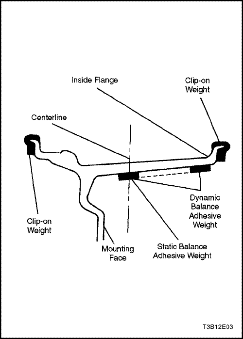
There are two types of tire and wheel balancing: staticand dynamic.
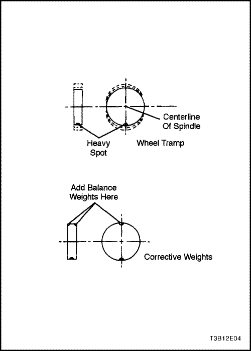
Static balance is the equal distribution of weight aroundthe wheel. Assemblies that are statically unbalancedcause a bouncing action called wheel tramp. This conditionmay eventually cause uneven tire wear.
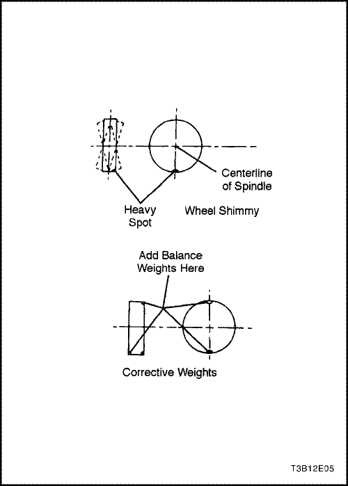
Dynamic balance is the equal distribution of weight oneach side of the centerline so that when the assemblyspins there is no tendency for it to move from side toside. Assemblies that are dynamically unbalanced maycause wheel shimmy.
General Balance Precautions
Remove all deposits of foreign material from the insideof the wheel.
Caution : Remove stones from the tread in order toavoid operator injury during spin balancing.
Inspect the tire for any damage. Balance the tire accordingto the equipment manufacturer’s recommendations.
Wheel Weights
If more than 85 grams (3.0 ounces) are needed to staticbalance the wheel, split the wheel weights as equally aspossible between the inboard and the outboard flanges.
Balancing the assemblies with factory aluminum wheelsrequires the use of special nylon-coated, clip-on wheelweights. These weights are designed to fit over thethicker rim flange of the aluminum wheel. Install theseweights with a plastic-tipped hammer.
Adhesive wheel weights are also available. Use the followingprocedure to install adhesive wheel weights.
Adhesive Wheel Weight Installation
- Clean the wheel by sanding it to bare alloy where the wheel weight will be installed.
- Use a clean cloth or paper towel saturated with a mixtureof half isopropyl alcohol and half water to wipe the place where the wheel weight will be installed.
- Dry the area with hot air. The surface of the wheel should be warm to the touch.
- Warm the adhesive backing on the wheel weights to room temperature.
- Remove the tape from the back of the weights. Do nottouch the adhesive surface.
- Apply the the wheel weight and press it on with hand pressure.
- Secure the wheel weight with a 70-110 N (16-25 lb) force applied with a roller.
Tire Chain Usage
Due to limited tire-to-body clearance on certain vehicles,recommendations for tire chain use are published in theOwner's Manual. When tire chains need to be used,most current Daewoo vehicles require SAE Class "S"tire chains. These may also be designated as 1100 Series,type PL tire chains. These chains are specificallydesigned to limit the "fly off" effect which occurs whenthe wheel rotates.
Be sure that only fine-link chains are used which do notadd more than 15 mm (0.590 inch), including the lock, tothe tread surface and the inner sides of the tires.
Manufacturers of tire chains have a specific chain sizefor each tire size to ensure a proper fit when the chain isinstalled. Be sure to purchase the correct chains for thetires on which they are to be used. Use rubber adjustersto take up any slack or clearance in loose chains.
Use of chains may adversely affect vehicle handling.
When tire chains are installed, follow these precautions:
- Adjust speed to road conditions.
- Avoid sharp turns.
- Avoid locked-wheel braking.
To prevent chain damage to the vehicle, install thechains on the front tires as tightly as possible. Tightenthem again after driving 0.4 to 0.8 kilometer (0.3 to0.5 mile). The use of chains on the rear tires is not recommendedbecause they may contact the vehicle andpossibly damage it. If chains must be used on the reartires, be sure there is sufficient clearance between thechains and the body. Do not exceed 70 km/h (45 mph)or the chain manufacturer's speed limit, if lower. Avoidlarge bumps, potholes, severe turns and any other maneuverswhich could cause the tires to bounce. Followany other instructions of the chain manufacturer whichdo not disagree with the above instructions.
Replacement Tires
A Tire Performance Criteria (TPC) specification numberis molded in the sidewall near the tire size of all originalequipment tires. This specification number assures thatthe tire meets performance standards for traction, endurance,dimensions, noise, handling and rolling resistance.Usually a specific TPC number is assignedeach tire size.
Caution : Do not mix different types of tires on thesame vehicle such as radial, bias and bias-beltedtires except in emergencies, because vehicle handlingmay be seriously affected and may result inloss of control.
Use only replacement tires with the same size, loadrange, and construction as the original. The use of anyother tire size or construction type may seriously affectride, handling, speedometer/odometer calibration, vehicleground clearance, and tire clearance to the bodyand the chassis. This does not apply to the spare tire furnishedwith the vehicle.
It is recommended that new tires be installed in pairs onthe same axle.
If it is necessary to replace only one tire, pair it with thetire having the most tread to equalize the braking action.
Although they may appear different in tread design, tiresbuilt by different manufacturers with identical TPC specificationsmay be used on the same vehicle.
All Season Tires
Most vehicles are now equipped with steel-belted allseason radial tires as standard equipment. These tiresqualify as snow tires, with a 37 percent higher averagerating for snow traction than the non-all season radialtires previously used. Other performance areas, such aswet traction, rolling resistance, tread life, and air retention,have also been improved. This was done by improvementsin both tread design and tread compounds.These tires are identified by an "M + S" molded in the tiresidewall following the size number. The suffix "MS" isalso molded in the sidewall after the TPC specificationnumber.
The optional handling tires used on some vehicles arenot all season tires. These will not have the "MS" markingafter the tire size or the TPC specification number.
Passenger Metric Sized Tires
All Daewoo vehicles now use Passenger (P) metricsized tires. P-metric tires are available in two loadranges: standard load (35 psi maximum) and extra load(41 psi maximum). Most passenger vehicle tires arestandard load.
Most P-metric tire sizes do not have exact correspondingalphanumeric tire sizes. For example, a P175/70R13is not exactly equal in size and load-carrying capacity toan FR70-13. For this reason, replacement tires shouldbe of the same TPC specification number as the originals.If P-metric tires must be replaced with other sizes,consult a tire dealer. Tire companies can best recommendthe closest match of alphanumeric to P-metricsizes within their own tire lines.
The metric term for measuring tire inflation pressure isthe kilopascal (kPa). Tire pressure may be printed inboth kPa and psi. One psi equals 6.895 kPa.
Tire LAbel
The tire label is permanently located on the rear face ofthe driver’s door and should be referred to for tire information.It lists the maximum vehicle load, the tire size(including the spare tire), and the cold inflation pressure(including the spare tire).
Spare Tire
This vehicle comes equipped with a full-sized spare tire and wheel for AP/LAAM countries. A temporary(T105/70D14) tire is available for European Countries.
Wheels
Wheels must be replaced if they are bent, dented, haveexcessive lateral or radial runout, leak air through welds,have elongated bolt holes, or if the wheel bolts won’tstay tight or are heavily rusted. Wheels with excessiverunout may cause vehicle vibration. Replacementwheels must be equivalent to the original equipmentwheels in load capacity, diameter, rim width, offset, andmounting configuration. A wheel of improper size or typemay affect wheel and bearing life, brake cooling,speedometer/odometer calibration, vehicle groundclearance, and tire clearance to the body and the chassis.The wheel offset is 49 ± 1 mm (1.93 ± 0.04 inches).Steel wheels may be identified by a two- or three-lettercode stamped into the rim near the valve stem. Aluminumwheels should have the code, the part number, andthe manufacturer ID cast into the back side.
Inflation of Tires
The pressure recommended for any vehicle line is carefullycalculated to give a satisfactory ride, handling,tread life, and load-carrying capacity.
Tire pressure should be checked monthly or before anyextended trip. Check the tires when they are cold, afterthe vehicle has sat for 3 hours or more or has been drivenless than 1 mile. Set the tire pressure to the specificationson the tire label located on the rear face of thedriver's door. Tire inflation pressure is also given under
"Tire Size and PressureSpecifications"in this section.
Valve caps or extensions should be on the valves tokeep dust and water out.
For sustained driving at speeds up to 140 km/h(85 mph), inflate the tires to the pressure recommendedon the tire. Sustained driving at speeds faster than140 km/h (85 mph), even if permitted by law, is not advisedunless the vehicle has special high-speed tiresavailable from many tire dealers. Tire pressures may increaseas much as 41 kPa (6 psi) when the tires are hot.
Higher than recommended tire pressure can cause:
- Hard ride.
- Tire bruising or damage.
- Rapid tread wear at the center of the tire.
Lower than recommended pressure can cause
- Tire squeal on turns.
- Hard steering.
- Rapid and uneven wear on the edges of the tread.
- Tire rim bruises and rupture.
- Tire cord breakage.
- High tire temperatures.
Unequal tire pressures on same axle can cause
- Uneven braking.
- Steering lead.
- Reduced handling.
- Swerve on acceleration.
- Torque steer.


