SECTION 4A
HYDRAULIC BRAKES
Caution : Disconnect the negative battery cable before removing or installing any electrical unit or when atool or equipment could easily come in contact with exposed electrical terminals. Disconnecting this cablewill help prevent personal injury and damage to the vehicle. The ignition must also be in LOCK unlessotherwise noted.otherwise noted.
SPECIFICATIONS
General Specifcations
Application | Millimeters | Inches |
Brake Drums: | . | . |
Inside Diameter | 200.00 | 7.87 |
Maximum Revore Diameter | 201.00 | 7.91 |
Out-to-Round | 0.04 | 0.001 |
Brake Rotors: | . | . |
Discard Thickness | 18.00 (22*) | 0.71 (0.86*) |
Lateral Runout (Installed) | 0.06 | 0.002 |
Rotor Diameter | 236.00 (256*) | 9.29 (10.08*) |
Rotor Thickness (New) | 20.00 (24*) | 0.79 (0.94*) |
Thickness Variation | 0.1 | 0.004 |
Master Cylinder: | . | . |
Bore Diameter | 22.22 | 0.87 |
Minimum Bore Diameter | 20.64 | 0.81 |
Caliper | . | . |
Piston Minimun Diameter | 52 (54*) | 2.05 (2.12*) |
Wheel Cylinder Diameter: | . | . |
Front | 52 (54*) | 2.05 (2.12*) |
Rear | 20.64 | 0.81 |
* : Optional (High Altitude or 1.6L DOHC)
Fastener Tightening Specifications
Application | N•m | Lb-Ft | Lb-In |
Frint brake hose-to-caliper bolt | 40 | 30 | 354 |
Bleeder Screw | 9 | 7 | 80 |
Caliper Maunting Bolt | 100 | 74 | 885 |
Hub-to-Disc Screws | 4.5 | 3.3 | 40 |
Dust Cover Screws | 4.5 | 3.3 | 40 |
Brake Lines | 16 | 12 | 142 |
Trim Panel Screws | 7 | - | 62 |
Brake Pedal-to-Pedal Bracket Hex nut | 22 | 16 | - |
COMPONENT LOCATOR
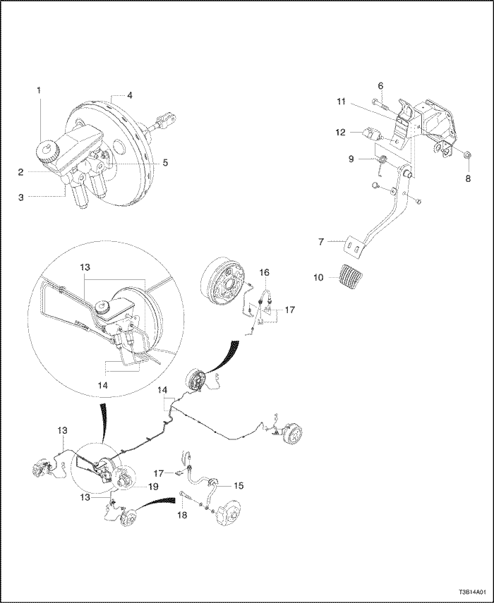
Brake System (ABS)
- Brake oil tank cap
- Brake oil tank
- Master cylinder
- Brake booster
- Brake booster nut
- Pedal bolt
- Pedal
- Pedal nut
- Spring
- Brake pedal cover
- Pedal bracket assembly
- Stoplamp switch
- Front brake pipe
- Rear brake pipe
- Front brake hose
- Rear brake hose
- E-ring
- Union bolt
- ABS assembly
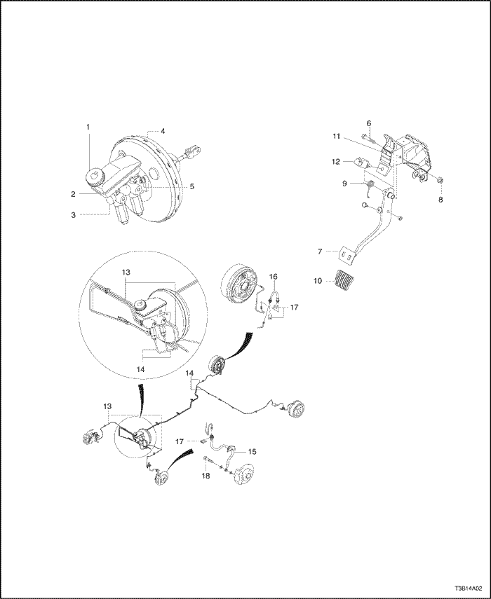
Brake System (NON-ABS)
- Brake oil tank cap
- Brake oil tank
- Master cylinder
- Brake booster
- Brake booster nut
- Pedal bolt
- Pedal
- Pedal nut
- Spring
- Brake pedal cover
- Pedal bracket assembly
- Stoplamp switch
- Front brake pipe
- Rear brake pipe
- Front brake hose
- Rear brake hose
- E-ring
- Union bolt
DIAGNOSIS
Brake System Testing
Brakes should be tested on a dry, clean, reasonablysmooth and level roadway. A true test of brake performancecannot be made if the roadway is wet, greasy, orcovered with loose dirt whereby all tires do not grip theroad equally. Testing will also be adversely affected if theroadway is crowned so as to throw the weight so roughlythat the wheels tend to bounce.
Test the brakes at different vehicle speeds with both lightand heavy pedal pressure; however, avoid locking thebrakes and sliding the tires. Locked brakes and slidingtires do not indicate brake efficiency since heavilybraked, but turning, wheels will stop the vehicle in lessdistance than locked brakes. More tire-to-road friction ispresent with a heavily braked, turning tire than with asliding tire.
Because of the high deceleration capability, a firmerpedal may be felt at higher deceleration levels.
There are three major external conditions that affectbrake performance:
- Tires having unequal contact and grip of the road willcause unequal braking. Tires must be equally inflated,and the tread pattern of the right and the lefttires must be approximately equal.
- Unequal loading of the vehicle can affect the brakeperformance since the most heavily loaded wheelsrequire more braking power, and thus more brakingeffort, than the others.
- Misalignment of the wheels, particularly conditions ofexcessive camber and caster, will cause the brakesto pull to one side.
To check for brake fluid leaks, hold constant foot pressureon the pedal with the engine running at idle and theshift lever in N (Neutral). If the pedal gradually falls awaywith the constant pressure, the hydraulic system may beleaking. Perform a visual check to confirm any suspectedleaks.
Check the master cylinder fluid level. While a slight dropin the reservoir level results from normal lining wear, anabnormally low level indicates a leak in the system. Thehydraulic system may be leaking either internally or externally.Refer to the procedure below to check the mastercylinder. Also, the system may appear to pass thistest while still having a slight leak. If the fluid level is ormal,check the vacuum booster pushrod length. If an incorrectpushrod length is found, adjust or replace therod.
Check the master cylinder using the following procedure:
- Check for a cracked master cylinder casting or brakefluid leaking around the master cylinder. Leaks are indicatedonly if there is at least one drop of fluid. Adamp condition is not abnormal.
- Check for a binding pedal linkage and for an incorrectpushrod length. If both of these parts are in satisfactorycondition, disassemble the master cylinder andcheck for an elongated or swollen primary cylinder orpiston seals. If swollen seals are found, substandardor contaminated brake fluid should be suspected. Ifcontaminated brake fluid is found, all the componentsshould be disassembled and cleaned, and all the rubbercomponents should be replaced. All of the pipesmust also be flushed.
Improper brake fluid, or mineral oil or water in the fluid,may cause the brake fluid to boil or cause deteriorationof the rubber components. If the primary piston cups inthe master cylinder are swollen, then the rubber partshave deteriorated. This deterioration may also be evidencedby swollen wheel cylinder piston seals on thedrum brake wheels.
If rubber deterioration is evident, disassemble all the hydraulicparts and wash the parts with alcohol. Dry theseparts with compressed air before reassembly to keep alcoholout of the system. Replace all the rubber parts inthe system, including the hoses. Also, when working onthe brake mechanisms, check for fluid on the linings. Ifexcessive fluid is found, replace the linings.
If the master cylinder piston seals are in satisfactorycondition, check for leaks or excessive heat conditions.If these conditions are not found, drain the fluid, flush themaster cylinder with brake fluid, refill the master cylinder,and bleed the system. Refer to
"Manual Bleeding the Brakes" in this section.
Brake Hose Inspection
The hydraulic brake hoses should be inspected at leasttwice a year. The brake hose assembly should bechecked for road hazard damage, cracks, chafing of theouter cover, and for leaks or blisters. Inspect the hosesfor proper routing and mounting. A brake hose that rubson a suspension component will wear and eventuallyfail. A light and a mirror may be needed for an adequateinspection. If any of the above conditions are observedon the brake hose, adjust or replace the hose as necessary.
Warning Lamp Operation
This brake system uses a BRAKE warning lamp locatedin the instrument cluster. When the ignition switch is inthe START position, the BRAKE warning lamp shouldglow and then go off when the ignition switch returns tothe RUN position.
The following conditions will activate the BRAKE lamp:
- Parking brake applied. The light should be on wheneverthe parking brake is applied and the ignitionswitch is ON.
- Low fluid level. A low fluid level in the master cylinderwill turn the BRAKE lamp on.
- As a test of the lamp circuit. Vehicles with antilockbrakes will illuminate the BRAKE lamp for 3 secondswhen the ignition starter is turned ON.
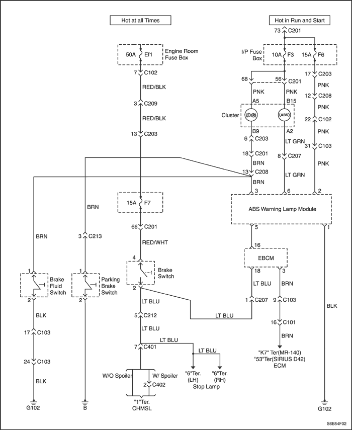
Brake Lamp Warning Circuit Diagnosis
Test Description
The number(s) below refer to step(s) on the diagnostictable.
- There are three possible symptoms of a problem:the brake warning lamp is always on; the brakewarning lamp is never on; the brake warning lampwill not operate for a particular function. This testtakes you to the appropriate starting point in the procedure.
- This test checks whether the Antilock Brake System(ABS) system has turned on the brake warninglamp. If the vehicle is not equipped with ABS, theanswer will be NO.
- These steps test for simple conditions that canturn on the brake warning lamp.
- This checks whether the brake fluid level switch isfaulty.
- This checks whether the parking brake switch isfaulty.
- This removes the circuit to the electronic brake controlmodule (EBCM) in a vehicle with ABS.
- This removes the parking brake switch circuit.
- This removes the brake fluid level switch circuit.
- This checks the only remaining circuitry that can activatethe brake warning lamp.
- This tests for the presence of battery voltage usedby both the oil pressure lamp and the brake warninglamp.
- This step begins a sequence that will restore voltageto the lamps.
- This checks for a burned out indicator lamp.
- This begins a sequence that will find the open thatprevents contact to ground needed to operate thelamp.
- This checks whether the ABS system has tried toturn on the brake warning lamp and could not. If thevehicle is not equipped with ABS, the answer is NO.
- This step begins a search for a problem in the parkingbrake switch circuit.
- This step begins a search for a problem in the brakefluid level switch circuit.
Brake Lamp Warning Circuit Diagnosis
| Step | Action | Value(s) | Yes | No |
| 1 | Turn the ignition ON. Is the brake warning lamp always on? | - | Go to Step 2 | Go to Step 19 |
| 2 | Check the ABS warning lamp. Is the ABS warning lamp also on? | - | Go to Step 3 | Go to Step 3 |
| 3 | Use a scan tool to check for diagnostic troublecodes (DTCs) and follow the procedures for anyDTCs found. Is the lamp still on? | - | Go to Step 4 | System OK |
| 4 | Release the parking brake fully. Is the lamp off? | - | System OK | Go to Step 5 |
| 5 | Check the brake fluid level. Is the fluid level acceptable? | - | Go to Step 7 | Go to Step 6 |
| 6 | - Fill the brake fluid reservior with clean DOT 3 equivalent hydraulic fluid.
- Replace the cap on the brake fluid reservoir.
Is the lamp stil on? | - | Go to Step 7 | System OK |
| 7 | Unplug the harness connector from the brake fluidsensor switch. Is the lamp still on? | - | Go to Step 9 | Go to Step 8 |
| 8 | Replace the parking brake lever switch. Is the repair complete? | - | System OK | - |
| 9 | - Reconnect the brake fluid level switch.
- Remove the rear console cover to expose theparking brake mechanism.
- Release the brake completely.
- Slide off the terminal with the BRN wire fromthe wiring harness.
Does the lamp go out? | - | Go to Step 10 | Go to Step 11 |
| 10 | Replace the switch. Is the repair complete? | - | System OK | - |
| 11 | Replace the terminal back onto the switch. Is the vehicle equipped with ABS? | - | Go to Step 12 | Go to Step 14 |
| 12 | Unplug connector C207. Does the lamp go out? | - | Go to Step 13 | Go to Step 14 |
| 13 | Repair the short to ground in circuit BRN between terminal 1 of connector C207 and terminal18 on the EBCM. Is the repair complete? | - | System OK | - |
| 14 | Disconnect connector C212. Is the lamp still on? | - | Go to Step 16 | Go to Step 15 |
| 15 | Repair the short to ground in circuit BRNbetween connector C212 and connector C207 orbetween connector C213 and the parking brakeswitch. Is the repair complete? | - | System OK | - |
| 16 | Disconnect connector C201. Does the lamp go out? | - | Go to Step 17 | Go to Step 18 |
| 17 | Repair the short to ground in circuit BRNbetween connector C201 and the brake fluid levelswitch. Is the repair complete? | - | System OK | - |
| 18 | Repair the short to ground in circuit BRNbetween terminal A5 of the instrument cluster andconnector C201or connector C213. Is the repair complete? | - | System OK | - |
| 19 | Check the brake lamp after doing each of thefollowing functions: - Apply the parking brake.
- Remove the cap from the brake fluid reservoir.
- Command the lamp on using a scan tool.
Does the brake warning lamp operate for any ofthese conditions? | - | Go to Step 32 | Go to Step 20 |
| 20 | Turn the ignition ON. Does the oil pressure indicator light? | - | Go to Step 24 | Go to Step 21 |
| 21 | Check fuse 3. Is the fuse in good condition? | - | Go to Step 23 | Go to Step 22 |
| 22 | Replace fuse 3 with another 10-amp fuse. Does the brake warning lamp function now? | - | System OK | - |
| 23 | Check Ef1 in the engine fuse block. Is Ef1 in good condition? | - | Go to step 25 | Go to Step 24 |
| 24 | Replace Ef1 with another 30-amp device. Is the repair complete? | - | System OK | - |
| 25 | - Unplug C206 from the connection box behind theleft-side kick panel. This is the largest connector atthe bottom of the box.
- Use a digital volt meter (DVM) to measure voltagefrom terminal A5 of the cluster.
Does the DVM indicate the specified voltage? | 11-14 v | Go to Step 27 | Go to Step 26 |
| 26 | Repair the open in circuit PNK from terminal A5in the connection box fuse 3 in the I/P fuse block. Is the repair complete? | - | System OK | - |
| 27 | - Reconnect harness terminal A5 to the connection box.
- Gain access to the rear of the instrument cluster.
- Unplug the instrument 10-pin cluster connector.
- Use a DVM to measure the voltage from terminalB9 of the instrument cluster connector to ground.
Does the DVM show the specified value? | 11-14 v | Go to Step 28 | Go to Step 29 |
| 28 | Repair the open in circuit PNK between terminal B9 and A5 or from there in circuit BRN to terminal 18 ofconnector C201 Is the repair complete? | - | System OK | - |
| 29 | Remove the brake indicator lamp from its socketand examine it. Is the lamp burned out? | - | Go to Step 30 | Go to Step 31 |
| 30 | Replace the brake indicator lamp. Is the repair complete? | - | System OK | - |
| 31 | - Return the brake indicator lamp to its socketthe instrument cluster.
- Look for the open in circuit BRN betweenterminal A5 of the cluster and terminal 18 of connector C201.
- Repair any open found in circuit BRN.
Is the repair complete? | - | System OK | - |
| 32 | Check the ABS lamp. Is the ABS lamp flashing? | - | Go to Step 33 | Go to Step 34 |
| 33 | Use a scan tool to determine what DTCs are presentand repair them according to the tables for the DTCsinvolved. Is the repair complete? | - | System OK | - |
| 34 | Try applying the parking brake fully. Does the brake warning lamp fail to light when theparking brake is applied? | - | Go to Step 35 | Go to Step 38 |
| 35 | - Expose the parking brake mechanism byremoving the rear console.Use a jumper to short the terminal from the
- BRN wire to ground.
Does the lamp come on? | - | Go to Step 36 | Go to Step 37 |
| 36 | Replace the parking brake switch or repair thegrounding between the parking brake switch and thebrake handle mounting or between the brake handlemounting and the vehicle body. Is the repair complete? | - | System OK | - |
| 37 | Repair the open in circuit BRN. This will be inone of two places: - The I/P harness between terminal B9 of cluster andterminal 3 of connector C213.
- The floor harness between terminal 3 ofconnector C213 and the parking brake switch.
Is the repair complete? | - | System OK | - |
| 38 | If the brake warning lamp is not indicating low brakefluid, remove the cap from the brake fluid reservoirto lift the sensor from the brake fluid. Does the lamp come on? | - | System OK | Go to Step 39 |
| 39 | - Unplug the harness connector from the sensor onthe brake fluid reservoir cap.
- Use a jumper to short the terminals in the harnessconnector together.
Does the lamp come on? | - | Go to Step 40 | Go to Step 41 |
| 40 | Install a new fluid level sensor switch into the brakefluid reservoir. Is the repair complete? | - | System OK | - |
| 41 | Use the jumper to short terminal 1 (BRN wire)to ground. Does the lamp come on? | - | Go to Step 42 | Go to Step 43 |
| 42 | Repair the open to ground in circuit BLK betweenthe terminal 2 (BLK wire) of the harness connectorfor the level sensor switch and ground G102 at theleft front corner of the vehicle. Is the repair complete? | - | System OK | - |
| 43 | Repair the open in circuit BRN. There are twopossible locations for this open: - The I/P harness between terminal B9 of cluster andterminal 18 of connector C201.
- The front harness between terminal 18 ofconnector C201and terminal 1 of the harnessconnector for the level sensor switch.
Is the repair complete? | - | System OK | - |
A low brake fluid level in the master cylinder will turn the BRAKE lamp ON. Refer to
"Brake System Testing" in thissection to test for fluid leaks.
MAINTENANCE AND REPAIR
ON-VEHICLE SERVICE


Manual Bleeding the Brakes
Important : Manual bleeding of the hydraulic modulatoris not possible. If air enters the antilock brake hydraulicmodulator, or if an unfilled modulator is installed, use thescan tool to bleed air out of the brake system. Replacementmodulators are shipped already filled and bled. Innormal on-vehicle service procedures involving themodulator, such as the procedure to replace the electronicbrake control module, air will not enter the modulator.In such cases, use the bleeding procedure in thissection.
- Remove the booster reserve by applying the brakesseveral times with the engine OFF until all the reserveis depleted.
Important : If the master cylinder is known or suspectedto have air in the bore, then it must be bled before anywheel cylinder or caliper is bled.
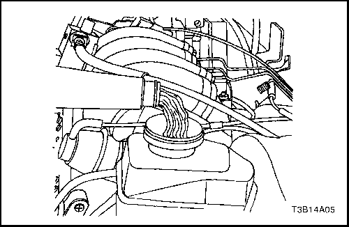
- Fill the master cylinder reservoir with brake fluid.Keep the master cylinder at least one-half full of fluidduring the bleeding operation.
- Disconnect the front brake line(s) at the master cylinder.
- Allow the brake fluid to fill the master cylinder until itbegins to flow from the front pipe connector port.
- Connect the front brake line(s) to the master cylinder.
Tighten
Tighten the brake lines to 16 N•m (12 lb-ft).
- Slowly push and hold the brake pedal one time.
- Loosen the front brake line at the master cylinder topurge all air from the cylinder.
- Tighten the brake line as in Step 5, and then releasethe brake pedal slowly. Wait 15 seconds before proceedingto the next step.
- Repeat the sequence, including the 15-second wait,until all the air is removed from the master cylinderbore.
Notice : Care must be taken to prevent brake fluid fromcontacting any painted surface to prevent damage to thepaint finish.
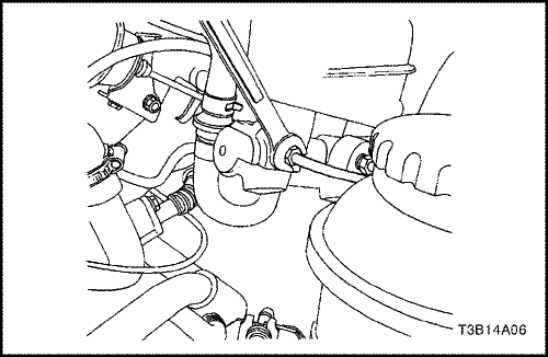
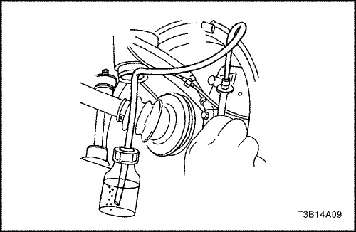
- After all the air has been removed at the forwardconnection(s), bleed the master cylinder at the rear(cowl) connection(s) in the same manner as with thefront connections.
- Attach a transparent tube over the valve. Allow thetube to hang submerged in brake fluid in a transparentcontainer.
- Slowly push and hold the brake pedal one time.
- Remove the bleeder cap and loosen the bleederscrew to purge the air from the cylinder.
- Tighten the bleeder screw.
Tighten
Tighten the bleeder screw to 9 N•m (80 lb-in).
- Slowly release the brake pedal. Wait 15 secondsbefore proceeding with the next step.
Important : Rapid pumping of the brake pedal pushesthe master cylinder secondary piston down the bore in amanner that makes it difficult to bleed the system.
- Repeat the sequence, including the 15-second wait,until all the air is removed. It may be necessary torepeat the sequence 10 or more times to remove allthe air.
- Locate the front bleeder caps.
- Proceed to bleed the front brakes following the appropriatesequence, beginning with Step 12.
- Check the brake pedal for sponginess. Repeat theentire bleeding procedure to correct this condition.
Brake Hose (Rear)
Removal Procedure
- Raise and suitably support the vehicle.
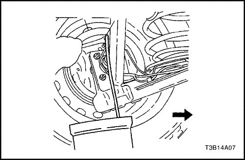
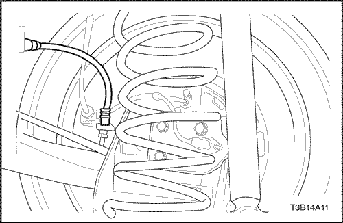
- Disconnect the brake lines from the brake hoses atthe body and the rear axle brackets.
- Remove both brake hose E-ring retainers.
- Remove the brake hoses from the brackets.
Installation Procedure
- Install the brake hoses to the body and the rear axlebrackets.
- Connect the brake lines to the brake hose.
Tighten
Tighten the brake lines to 16 N•m (12 lb-ft).
- Install the brake hose retainers.
- Lower the vehicle.
- Bleed the brake system. Refer to "Manual Bleedingthe Brakes"in this section.
- Check the brake system for leaks.
Brake Hose (Front)
Removal Procedure
- Raise and suitably support the vehicle.
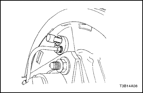
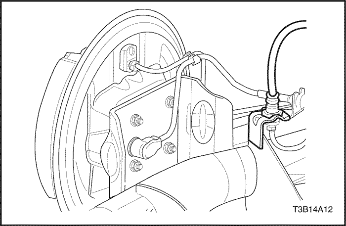
- Disconnect the brake line from the brake hose supportbracket on the wheel housing.
- Remove the E-ring retainer.
- Remove the brake hose from the wheel housingbracket.
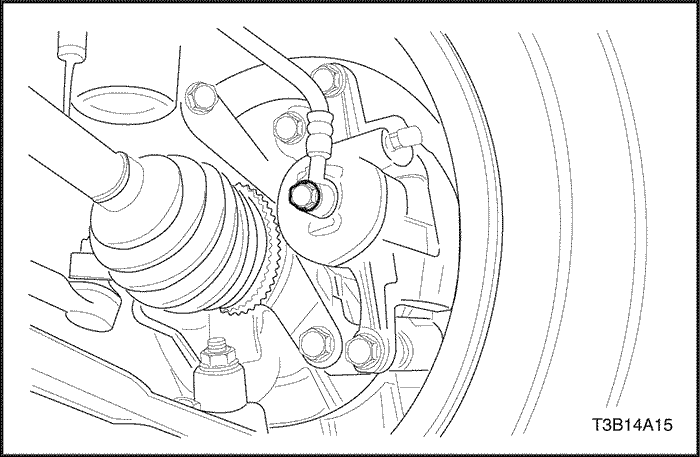
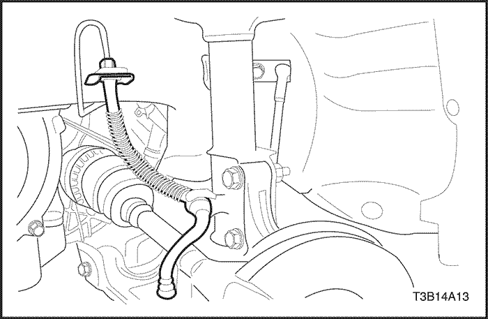
- Remove the bolt from the brake caliper.
- Remove the seal rings and the brake hose.
Installation Procedure
- Install the new brake hose to the caliper with new sealrings and the bolt.
Tighten
Tighten the front brake hose-to-caliper bolt to 40 N•m(30 lb-ft).
- Install the brake hose and the E-ring retainer to thewheel housing bracket.
- Connect the brake line to the brake hose.
Tighten
Tighten the brake line to 16 N•m (12 lb-ft).
- Lower the vehicle.
- Bleed the brake system. Refer to "Manual Bleedingthe Brakes"in this section.
- Check the brake system for leaks.
Stoplamp Switch
Removal Procedure
- Disconnect the negative battery cable.
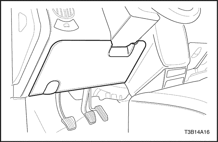
- Remove the trim panel screws.
- Remove the trim panel.
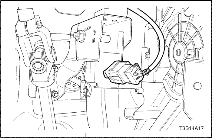
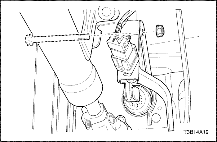
- Turn the stoplamp switch and the connector assembly,and pull it from the brake pedal bracket.
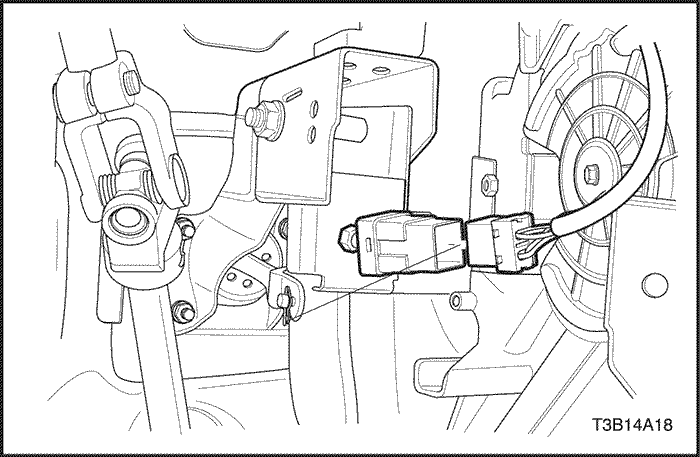
- Separate the stoplamp switch from the connector toreplace the stoplamp switch.
Installation Procedure
- Install the connector to the stoplamp switch.
- Turn the stoplamp switch and the connector assembly,and twist it into the brake pedal bracket.
- Press the brake pedal and pull the switch plunger toits maximum setting to adjust the switch.
- Release the plunger and pull up on the pedal.
- Install the trim panel screws.
Tighten
Tighten the trim panel screws to 7 N•m (62 lb-in).
- Press the brake pedal and pull the switch plunger toits maximum setting to adjust the switch.
Brake Pedal
Removal Procedure
- Remove the screws that hold the trim panel to the instrumentpanel.
- Remove the trim panel.
- Remove the stoplamp switch. Refer to "StoplampSwitch"in this section.
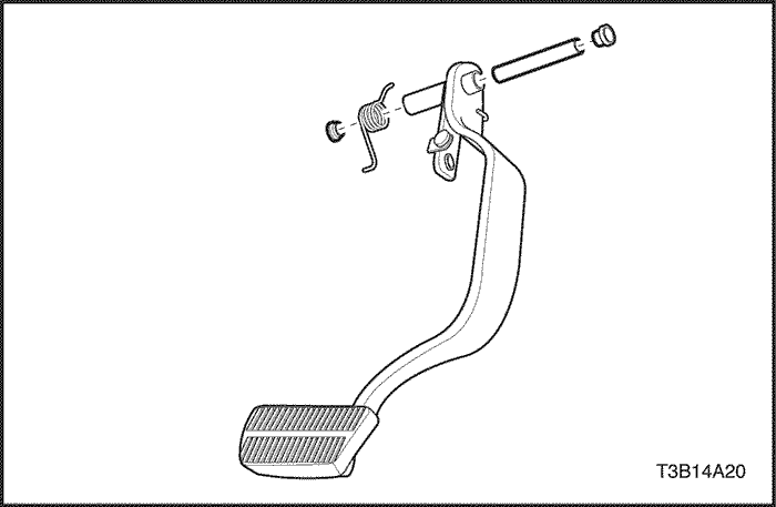
- Disconnect the retaining ring, the pin, and the springfrom the pushrod/brake pedal connection.
- Remove the pedal mounting shaft and nut.
- Remove the brake pedal, exposing the brake boosterpushrod and the pedal-to-dash panel bracket.
- Remove the brake pedal cover.
Installation Procedure
- Install a new brake pedal cover, if needed.
- Coat the pedal shaft with grease.
- Position the brake pedal on the pedal-to-dash panelbracket and the pedal shaft.
- Place the nut on the pedal mounting shaft.
Tighten
Tighten the brake pedal-to-pedal bracket nut to22 N•m (16 lb-ft.)
- Install the pushrod to the pedal with the pin and theretaining ring.
- Install the spring on the shaft in its original position.
- Connect the stoplamp switch and the connector assemblyby twisting it into the pedal bracket.
- Install the trim panel with the screws.
Tighten
Tighten the trim panel screws to 7 N•m (62 lb-in).
GENERAL DESCRIPTIONAND SYSTEM OPERATION
Hydraulic Fluid
Master cylinder fluid should meet the DOT 3 specification.
Use only clear fluid from a sealed container. Fluid that isexposed to the air will absorb moisture. Water in themaster cylinder fluid will cause the fluid to boil and therubber components to deteriorate.
Thoroughly clean the master cylinder reservoir cap beforeremoving it. Do not let any dirt or foreign material fallinto the fluid reservoir.
There is a fluid level switch in the master cylinder reservoir.When the fluid level is low, the BRAKE lamp in theinstrument cluster will turn on. The correct master cylinderfluid level is marked on the left side of the master cylinderreservoir. If the fluid level is below the MINindicator mark, check the hydraulic brake system forleaks, and then refill the reservoir to the MAX indicatormark.