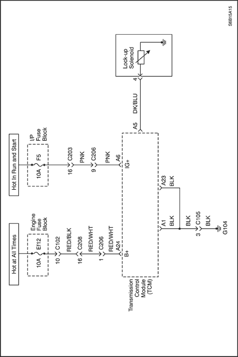


Diagnostic Trouble Code (DTC) P0741
Torque Converter Clutch (TCC) Circuit Performance or Stuck OFF
Conditions for Running the DTC
- Engine revolution is greater than 600 rpm.
- No emergency mode.
- 5 seconds have passed after P, R, N, 2, L→D.
- 2 seconds have passed after gear selector changed.
- Lock-up ON.
- 4, 5 seconds have passed after lock-up OFF to ON.
- Oil temperature is 20°C (68°F) or greater.
- No failure of input speed sensor/output speed sensor/TR switch/engine coolant temperature sensor/throttle position sensor/shift solenoid A, B/engine revolution.
Conditions for Setting the DTC
- Above detection continuously occurs 1 time.
Action Taken When the DTC Sets
- TCM will request the illumination of MIL and store DTC when TCM detects failures on two consecutive ignition cycles.
Conditions for Clearing the DTC
- The TCM turns off the MIL when no further failures detected for three consecutive ignition cycles.
- The scan tool can clear the DTC from the TCM history.
- The TCM clears the DTC from the TCM history memory after forty consecutive warm up cycles without fault.
Cause of Failure
- Lockup solenoid
- Inside A/T
- Inside valve body
- TCM
DTC P0741 - Torque Converter Clutch (TCC) Circuit Performance or Stuck OFF
| Step | Action | Value(s) | Yes | No |
| 1 | - Turn the ignition OFF.
- Install the Scan tool.
- With the engine OFF, turn the ignition switch to the ON position.
- Select Store Freeze Frame/Failure Records from the Diagnostic Trouble Codes Information menu.
- Store Freeze Frame/Failure Records.
- Select Clear DTC Information from the Diagnostic Trouble Codes Information menu.
- Clear DTC Information.
- Perform two vehicle drive cycles.
Is the Malfunction Indicator Lamp (MIL) ON? | - | Go to Step 2 | Repair the temporary connection failure of connector (Refer to "Wiring Harness and Connector Inspection" in this section.) |
| 2 | - Select Request DTC by Status from the Diagnostic Trouble Codes Information menu.
- Request DTC by Status.
Is DTC P0741 displayed? | - | Go to Step 3 | Repair the temporary connection failure of connector (Refer to "Wiring Harness and Connector Inspection" in this section.) |
| 3 | - Turn the ignition OFF.
- Replace the master TCM and perform simulation test again under user condition.
Is DTC P0741 reappeared? | - | Go to Step 4 | Replace the TCM |
| 4 | - Estimate the failure of lockup solenoid, lockup clutch or internal valve body.
- Inspect the lockup solenoid. Refer to "Unit Inspection" in this section.
Is the condition of lockup solenoid OK? | - | Go to Step 5 | Replace lockup solenoid |
| 5 | - Estimate the failure of lockup clutch or internal valve body.
Is problem found? | - | Replace the valve body assembly | System OK |
Diagnostic Trouble Code (DTC) P0742
Torque Converter Clutch (TCC) Circuit Stuck ON
Conditions for Running the DTC
- Engine revolution is greater than 600 rpm.
- No emergency mode.
- 5 seconds have passed after P, R, N, 2, L→D.
- 2 seconds have passed after gear selector changed.
- Lock-up OFF.
- 4.5 seconds have passed after lock-up ON to OFF.
- Oil temperature is 20°C (68°F) or greater.
- No failure of input speed sensor/output speed sensor/TR switch/engine coolant temperature sensor/throttle position sensor/shift solenoid A, B/engine revolution.
Conditions for Setting the DTC
- Above detection continuously occurs 1 time.
Action Taken When the DTC Sets
- TCM will request the illumination of MIL and store DTC when TCM detects failures on two consecutive ignition cycles.
Conditions for Clearing the DTC
- The TCM turns off the MIL when no further failures detected for three consecutive ignition cycles.
- The scan tool can clear the DTC from the TCM history.
- The TCM clears the DTC from the TCM history memory after forty consecutive warm up cycles without fault.
Cause of Failure
- Lockup solenoid
- Inside A/T
- Inside valve body
- TCM
DTC P0742 - Torque Converter Clutch (TCC) Circuit Stuck ON
| Step | Action | Value(s) | Yes | No |
| 1 | - Turn the ignition OFF.
- Install the Scan tool.
- With the engine OFF, turn the ignition switch to the ON position.
- Select Store Freeze Frame/Failure Records from the Diagnostic Trouble Codes Information menu.
- Store Freeze Frame/Failure Records.
- Select Clear DTC Information from the Diagnostic Trouble Codes Information menu.
- Clear DTC Information.
- Perform two vehicle drive cycles.
Is the Malfunction Indicator Lamp (MIL) ON? | - | Go to Step 2 | Repair the temporary connection failure of connector (Refer to "Wiring Harness and Connector" in this section.) |
| 2 | - Select Request DTC by Status from the Diagnostic Trouble Codes Information menu.
- Request DTC by Status.
Is DTC P0742 displayed? | - | Go to Step 3 | Repair the temporary connection failure of connector (Refer to "Wiring Harness and Connector" in this section.) |
| 3 | - Turn the ignition OFF.
- Replace the master TCM and perform simulation test again under user condition.
Is DTC P0742 reappeared? | - | Go to Step 4 | Replace the TCM |
| 4 | - Estimate the failure of lockup solenoid, lockup clutch or internal valve body.
- Inspect the lockup solenoid. Refer to "Unit Inspection" in this section.
Is the condition of lockup solenoid OK? | - | Go to Step 5 | Replace lockup solenoid |
| 5 | - Estimate the failure of lockup clutch or internal valve body.
Is problem found? | - | Replace the valve body assembly | System OK |
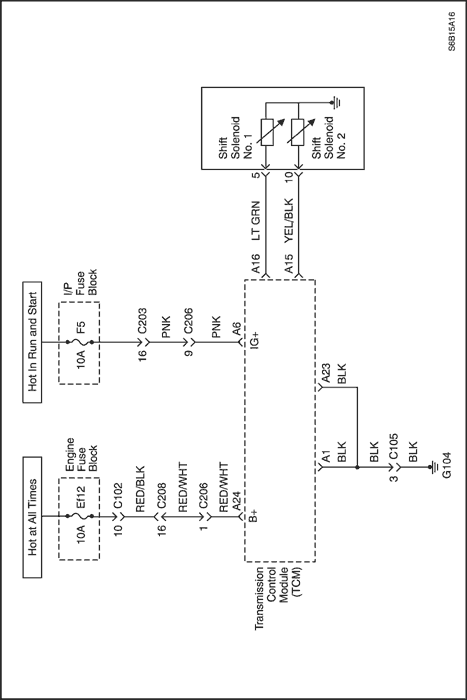
Diagnostic Trouble Code (DTC) P0751
Shift Solenoid 1 (SS1) Performance or Stuck OFF
Conditions for Running the DTC
- Engine revolution is 600 rpm or greater.
- No emergency mode.
- 5 seconds have passed after P, R, N, 2, L→D.
- 2 seconds have passed after gear selector changed.
- Vehicle speed is 15 km/h (9mph) or greater.
- Engine coolant temperature is 60°C (140°F) or greater.
- Oil temperature is 20°C (68°F) or greater.
- No failure of input speed sensor/output speed sensor/TR switch/engine coolant temperature sensor/throttle position sensor/shift solenoid A, B/engine revolution.
Conditions for Setting the DTC
- Above detection continuously occurs 1 time.
Action Taken When the DTC Sets
- TCM will request the illumination of MIL and store DTC when TCM detects failures on two consecutive ignition cycles.
Conditions for Clearing the DTC
- The TCM turns off the MIL when no further failures detected for three consecutive ignition cycles.
- The scan tool can clear the DTC from the TCM history.
- The TCM clears the DTC from the TCM history memory after forty consecutive warm up cycles without fault.
Cause of Failure
- Shift Solenoid 1 (SS1)
- Inside Valve Body
- TCM
DTC P0751 - Shift Solenoid 1 (SS1) Performance or Stuck OFF
| Step | Action | Value(s) | Yes | No |
| 1 | - Turn the ignition OFF.
- Install the Scan tool.
- With the engine OFF, turn the ignition switch to the ON position.
- Select Store Freeze Frame/Failure Records from the Diagnostic Trouble Codes Information menu.
- Store Freeze Frame/Failure Records.
- Select Clear DTC Information from the Diagnostic Trouble Codes Information menu.
- Clear DTC Information.
- Perform two vehicle drive cycles.
Is the Malfunction Indicator Lamp (MIL) ON? | - | Go to Step 2 | Repair the temporary connection failure of connector (Refer to "Wiring Harness and Connector" in this section.) |
| 2 | - Select Request DTC by Status from the Diagnostic Trouble Codes Information menu.
- Request DTC by Status.
Is DTC P0751 displayed? | - | Go to Step 3 | Repair the temporary connection failure of connector (Refer to "Wiring Harness and Connector" in this section.) |
| 3 | - Turn the ignition OFF.
- Replace the master TCM and perform simulation test again under user condition.
Is DTC P0751 reappeared? | - | Go to Step 4 | Replace the TCM. |
| 4 | - Estimate the failure of Shift Solenoid 1 or internal valve body.
- Inspect the SS1. Refer to "Unit Inspection" in this section.
Is the condition of SS1 OK? | - | Replace the valve body assembly. | Replace Shift Solenoid 1 (SS1). |
Diagnostic Trouble Code (DTC) P0752
Shift Solenoid 1 (SS1) Performance or Stuck ON
Conditions for Running the DTC
- Engine revolution is 600 rpm or greater.
- No emergency mode.
- 5 seconds have passed after P, R, N, 2, L→D.
- 2 seconds have passed after gear selector changed.
- Vehicle speed is 15 km/h (9mph) or greater.
- Engine coolant temperature is 60°C (140°F) or greater.
- Oil temperature is 20°C (68°F) or greater.
- No failure of input speed sensor/output speed sensor/TR switch/engine coolant temperature sensor/throttle position sensor/shift solenoid A, B/engine revolution.
Conditions for Setting the DTC
- Above detection continuously occurs 1 time.
Action Taken When the DTC Sets
- TCM will request the illumination of MIL and store DTC when TCM detects failures on two consecutive ignition cycles.
Conditions for Clearing the DTC
- The TCM turns off the MIL when no further failures detected for three consecutive ignition cycles.
- The scan tool can clear the DTC from the TCM history.
- The TCM clears the DTC from the TCM history memory after forty consecutive warm up cycles without fault.
Cause of Failure
- Shift Solenoid 1 (SS1)
- Inside Valve Body
- TCM
DTC P0752 - Shift Solenoid 1 (SS1) Performance or Stuck ON
| Step | Action | Value(s) | Yes | No |
| 1 | - Turn the ignition OFF.
- Install the Scan tool.
- With the engine OFF, turn the ignition switch to the ON position.
- Select Store Freeze Frame/Failure Records from the Diagnostic Trouble Codes Information menu.
- Store Freeze Frame/Failure Records.
- Select Clear DTC Information from the Diagnostic Trouble Codes Information menu.
- Clear DTC Information.
- Perform two vehicle drive cycles.
Is the Malfunction Indicator Lamp (MIL) ON? | - | Go to Step 2 | Repair the temporary connection failure of connector (Refer to "Wiring Harness and Connector" in this section.) |
| 2 | - Select Request DTC by Status from the Diagnostic Trouble Codes Information menu.
- Request DTC by Status.
Is DTC P0752 displayed? | - | Go to Step 3 | Repair the temporary connection failure of connector (Refer to "Wiring Harness and Connector" in this section.) |
| 3 | - Turn the ignition OFF.
- Replace the master TCM and perform simulation test again under user condition.
Is DTC P0752 reappeared? | - | Go to Step 4 | Replace the TCM. |
| 4 | - Estimate the failure of Shift Solenoid 1 or internal valve body.
- Inspect the SS1. Refer to "Unit Inspection" in this section.
Is the condition of SS1 OK? | - | Replace the valve body assembly. | Replace Shift Solenoid 1 (SS1). |
Diagnostic Trouble Code (DTC) P0756
Shift Solenoid 2 (SS2) Performance or Stuck OFF
Conditions for Running the DTC
- Engine revolution is 600 rpm or greater.
- No emergency mode.
- 5 seconds have passed after P, R, N, 2, L→D.
- 2 seconds have passed after gear selector changed.
- Vehicle speed is 15 km/h (9mph) or greater.
- Engine coolant temperature is 60°C (140°F) or greater.
- Oil temperature is 20°C (68°F) or greater.
- No failure of input speed sensor/output speed sensor/TR switch/engine coolant temperature sensor/throttle position sensor/shift solenoid A, B/engine revolution.
Conditions for Setting the DTC
- Above detection continuously occurs 1 time.
Action Taken When the DTC Sets
- TCM will request the illumination of MIL and store DTC when TCM detects failures on two consecutive ignition cycles.
Conditions for Clearing the DTC
- The TCM turns off the MIL when no further failures detected for three consecutive ignition cycles.
- The scan tool can clear the DTC from the TCM history.
- The TCM clears the DTC from the TCM history memory after forty consecutive warm up cycles without fault.
Cause of Failure
- Shift Solenoid 2 (SS2)
- Inside Valve Body
- TCM
DTC P0756 - Shift Solenoid 2 (SS2) Performance or Stuck OFF
| Step | Action | Value(s) | Yes | No |
| 1 | - Turn the ignition OFF.
- Install the Scan tool.
- With the engine OFF, turn the ignition switch to the ON position.
- Select Store Freeze Frame/Failure Records from the Diagnostic Trouble Codes Information menu.
- Store Freeze Frame/Failure Records.
- Select Clear DTC Information from the Diagnostic Trouble Codes Information menu.
- Clear DTC Information.
- Perform two vehicle drive cycles.
Is the Malfunction Indicator Lamp (MIL) ON? | - | Go to Step 2 | Repair the temporary connection failure of connector (Refer to "Wiring Harness and Connector Inspection" in this section.) |
| 2 | - Select Request DTC by Status from the Diagnostic Trouble Codes Information menu.
- Request DTC by Status.
Is DTC P0756 displayed? | - | Go to Step 3 | Repair the temporary connection failure of connector (Refer to "Wiring Harness and Connector Inspection" in this section.) |
| 3 | - Turn the ignition OFF.
- Replace the master TCM and perform simulation test again under user condition.
Is DTC P0756 reappeared? | - | Go to Step 4 | Replace the TCM. |
| 4 | - Estimate the failure of Shift Solenoid 2 or internal valve body.
- Inspect the SS2. Refer to "Unit Inspection" in this section.
Is the condition of SS2 OK? | - | Replace the valve body assembly. | Replace Shift Solenoid 2 (SS2). |
Diagnostic Trouble Code (DTC) P0757
Shift Solenoid 2 (SS2) Performance or Stuck ON
Conditions for Running the DTC
- Engine revolution is 600 rpm or greater.
- No emergency mode.
- 5 seconds have passed after P, R, N, 2, L→D.
- 2 seconds have passed after gear selector changed.
- Vehicle speed is 15 km/h (9mph) or greater.
- Engine coolant temperature is 60°C (140°F) or greater.
- Oil temperature is 20°C (68°F) or greater.
- No failure of input speed sensor/output speed sensor/TR switch/engine coolant temperature sensor/throttle position sensor/shift solenoid A, B/engine revolution.
Conditions for Setting the DTC
- Above detection continuously occurs 1 time.
Action Taken When the DTC Sets
- TCM will request the illumination of MIL and store DTC when TCM detects failures on two consecutive ignition cycles.
Conditions for Clearing the DTC
- The TCM turns off the MIL when no further failures detected for three consecutive ignition cycles.
- The scan tool can clear the DTC from the TCM history.
- The TCM clears the DTC from the TCM history memory after forty consecutive warm up cycles without fault.
Cause of Failure
- Shift Solenoid 2 (SS2)
- Inside Valve Body
- TCM
DTC P0757 - Shift Solenoid 2 (SS2) Performance or Stuck ON
| Step | Action | Value(s) | Yes | No |
| 1 | - Turn the ignition OFF.
- Install the Scan tool.
- With the engine OFF, turn the ignition switch to the ON position.
- Select Store Freeze Frame/Failure Records from the Diagnostic Trouble Codes Information menu.
- Store Freeze Frame/Failure Records.
- Select Clear DTC Information from the Diagnostic Trouble Codes Information menu.
- Clear DTC Information.
- Perform two vehicle drive cycles.
Is the Malfunction Indicator Lamp (MIL) ON? | - | Go to Step 2 | Repair the temporary connection failure of connector (Refer to "Wiring Harness and Connector Inspection" in this section.) |
| 2 | - Select Request DTC by Status from the Diagnostic Trouble Codes Information menu.
- Request DTC by Status.
Is DTC P0757 displayed? | - | Go to Step 3 | Repair the temporary connection failure of connector (Refer to "Wiring Harness and Connector Inspection" in this section.) |
| 3 | - Turn the ignition OFF.
- Replace the master TCM and perform simulation test again under user condition.
Is DTC P0757 reappeared? | - | Go to Step 4 | Replace the TCM. |
| 4 | - Estimate the failure of Shift Solenoid 2 or internal valve body.
- Inspect the SS2. Refer to "Unit Inspection" in this section.
Is the condition of SS2 OK? | - | Replace the valve body assembly. | Replace Shift Solenoid 2 (SS2). |
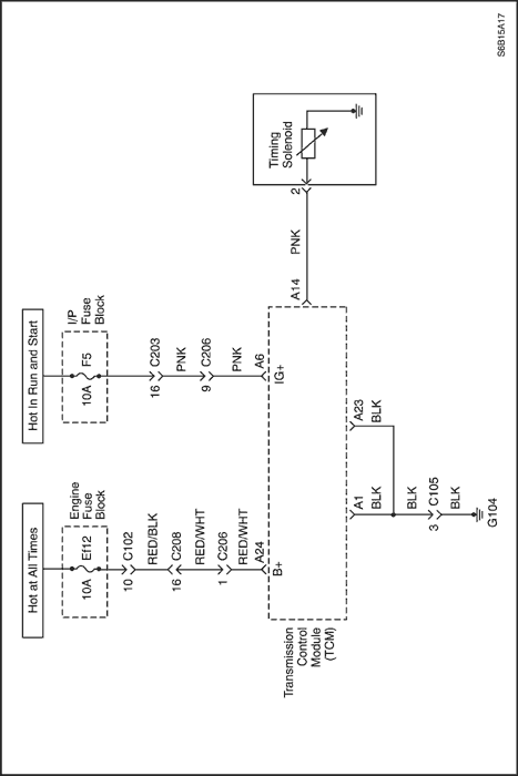
Diagnostic Trouble Code (DTC) P0787
Timing Solenoid (ST) Electrical (Ground Short)
Conditions for Running the DTC
- No emergency mode.
- TCM detects that the OFF signal of the Timing Solenoid (ST) monitor, when ST driver ouputs the ON signal (0V) for 0.1 seconds continuously.
Conditions for Setting the DTC
- Above detection continuously occurs 3 times.
Action Taken When the DTC Sets
- TCM will request the illumination of MIL and store DTC when TCM detects a failure on the first ignition cycle.
- After failure decision : emergency mode
Conditions for Clearing the DTC
- The TCM turns off the MIL when no further failures detected for three consecutive ignition cycles.
- The scan tool can clear the DTC from the TCM history.
- The TCM clears the DTC from the TCM history memory after forty consecutive warm up cycles without fault.
- TCM detects the ON signal of the ST monitor, when ST driver outputs the ON signal for 100 ms.
Cause of Failure
- Wiring harness or connector between Timing Solenoid (ST) and TCM
- ST
- TCM
DTC P0787 - Timing Solenoid (ST) Electrical (Ground Short)
| Step | Action | Value(s) | Yes | No |
| 1 | - Turn the ignition OFF.
- Install the Scan tool.
- With the engine OFF, turn the ignition switch to the ON position.
- Select Store Freeze Frame/Failure Records from the Diagnostic Trouble Codes Information menu.
- Store Freeze Frame/Failure Records.
- Select Clear DTC Information from the Diagnostic Trouble Codes Information menu.
- Clear DTC Information.
- Perform one vehicle drive cycle.
Is the Malfunction Indicator Lamp (MIL) ON? | - | Go to Step 2 | Repair the temporary connection failure of connector (Refer to "Wiring Harness and Connector Inspection" in this section.) |
| 2 | - Select Request DTC by Status from the Diagnostic Trouble Codes Information menu.
- Request DTC by Status.
Is DTC P0787 displayed? | - | Go to Step 3 | Repair the temporary connection failure of connector (Refer to "Wiring Harness and Connector Inspection" in this section.) |
| 3 | - Turn the ignition OFF.
- Inspect the resistance between the vehicle harness and Timing Solenoid (ST). Refer to "Unit Inspection" in this section.
- Disconnect the TCM connector (X-1) and inspect the resistance between the terminal A14 and A23.
Is the measurement within the specified value? | 20°C (68°F) 11-16 Ω | Go to Step 4 | Go to Step 5 |
| 4 | - Estimate the failure of between the vehicle wiring harness connector and TCM.
- Inspect the connector. Refer to "Wiring Harness and Connector Inspection" in this section.
- Inspect the connection condition between the connectors (C-1).
Is the connection condition OK? | - | Go to Step 6 | Repair the wiring harness connectors. |
| 5 | - Estimate the failure of between the vehicle harness and ST.
- Disconnect the connector (X-3) of T/M wire and inspect the resistance between ST connector terminal 2 and ground.
Is the measurement within the specified value? | 20°C (68°F) 11-16 Ω | Go to Step 7 | Go to Step 8 |
| 6 | - Replace the master TCM.
- Perform the reproducing test under user condition after confirming no DTC.
Is DTC displayed? | - | Repair the temporary connection failure of connector (Refer to "Wiring Harness and Connector Inspection" in this section.) | Replace the TCM |
| 7 | - Estimate the failure of the vehicle wiring harness or between connectors.
- Inspect continuity and short circuit for the vehicle wiring harness and inspect the connection condition between connectors (C-3). Refer to "Wiring Harness and Connector Inspection" in this section.
Is the condition OK? | - | Repair the temporary connection failure of connector | Replace the vehicle harness or adjustment between connectors |
| 8 | - Estimate the failure of T/M wire or between connectors of ST.
- Inspect the ST. Refer to "Unit Inspection" in this section.
Is the problem found? | - | Replace the ST | Go to Step 9 |
| 9 | - Estimate the failure of T/M wire.
- Inspect continuity and short circuit for the T/M wire and inspect the connection condition between connectors (C-6). Refer to "Wiring Harness and Connector Inspection" in this section.
Is the condition OK? | - | Repair the temporary connection failure of connector | Replace the T/M wire or adjustment between connectors |
Diagnostic Trouble Code (DTC) P0788
Timing Solenoid (ST) Electrical (Open or Power Short)
Conditions for Running the DTC
- No emergency mode.
- TCM detects that the ON signal (12V) of the Timing Solenoid(ST) monitor, when ST driver ouputs the OFF signal (0V) for 0.5 seconds continuously.
Conditions for Setting the DTC
- Above detection continuously occurs 3 times.
Action Taken When the DTC Sets
- TCM will request the illumination of MIL and store DTC when TCM detects a failure on the first ignition cycle.
- After failure decision : emergency mode
Conditions for Clearing the DTC
- The TCM turns off the MIL when no further failures detected for three consecutive ignition cycles.
- The scan tool can clear the DTC from the TCM history.
- The TCM clears the DTC from the TCM history memory after forty consecutive warm up cycles without fault.
- TCM detects the OFF signal of the ST monitor when ST driver outputs the OFF signal for 100 ms continuously.
Cause of Failure
- Wiring harness or connector between Timing Solenoid (ST) and TCM
- ST
- TCM
DTC P0788 - Timing Solenoid (ST) Electrical (Open or Power Short)
| Step | Action | Value(s) | Yes | No |
| 1 | - Turn the ignition OFF.
- Install the Scan tool.
- With the engine OFF, turn the ignition switch to the ON position.
- Select Store Freeze Frame/Failure Records from the Diagnostic Trouble Codes Information menu.
- Store Freeze Frame/Failure Records.
- Select Clear DTC Information from the Diagnostic Trouble Codes Information menu.
- Clear DTC Information.
- Perform one vehicle drive cycle.
Is the Malfunction Indicator Lamp (MIL) ON? | - | Go to Step 2 | Repair the temporary connection failure of connector (Refer to "Wiring Harness and Connector Inspection" in this section.) |
| 2 | - Select Request DTC by Status from the Diagnostic Trouble Codes Information menu.
- Request DTC by Status.
Is DTC P0788 displayed? | - | Go to Step 3 | Repair the temporary connection failure of connector (Refer to "Wiring Harness and Connector Inspection" in this section.) |
| 3 | - Turn the ignition OFF.
- Inspect the resistance between the vehicle harness and Timing Solenoid (ST). Refer to "Unit Inspection" in this section.
- Disconnect the TCM connector (X-1) and inspect the resistance between the terminal A14 and A23.
Is the measurement within the specified value? | 20°C (68°F) 11-16 Ω | Go to Step 4 | Go to Step 5 |
| 4 | - Estimate the failure of between the vehicle wiring harness connector and TCM.
- Inspect the connector. Refer to "Wiring Harness and Connector Inspection" in this section.
- Inspect the connection condition between the connectors (C-1).
Is the connection condition OK? | - | Go to Step 6 | Repair the wiring harness connectors. |
| 5 | - Estimate the failure of between the vehicle harness and ST.
- Disconnect the connector (X-3) of T/M wire and inspect the resistance between ST connector terminal 2 and ground.
Is the measurement within the specified value? | 20°C (68°F) 11-16 Ω | Go to Step 7 | Go to Step 8 |
| 6 | - Replace the master TCM.
- Perform the reproducing test under user condition after confirming no DTC.
Is DTC displayed? | - | Repair the temporary connection failure of connector (Refer to "Wiring Harness and Connector Inspection" in this section.) | Replace the TCM |
| 7 | - Estimate the failure of the vehicle wiring harness or between connectors.
- Inspect continuity and short circuit for the vehicle wiring harness and inspect the connection condition between connectors (C-3). Refer to "Wiring Harness and Connector Inspection" in this section.
Is the condition OK? | - | Repair the temporary connection failure of connector | Replace the vehicle harness or adjustment between connectors |
| 8 | - Estimate the failure of T/M wire or between connectors of ST.
- Inspect the ST. Refer to "Unit Inspection" in this section.
Is the problem found? | - | Replace the ST | Go to Step 9 |
| 9 | - Estimate the failure of T/M wire.
- Inspect continuity and short circuit for the T/M wire and inspect the connection condition between connectors (C-6). Refer to "Wiring Harness and Connector Inspection" in this section.
Is the condition OK? | - | Repair the temporary connection failure of connector | Replace the T/M wire or adjustment between connectors |
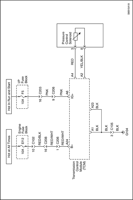
Diagnostic Trouble Code (DTC) P0962
Pressure Control Solenoid (PCS) Electrical (Low)
Conditions for Running the DTC
- No emergency mode.
- Input A/D value is 68 (0.018V) or less for 0.5 seconds continuously.
Conditions for Setting the DTC
- Above detection continuously occurs 25 times.
Action Taken When the DTC Sets
- TCM will request the illumination of MIL and store DTC when TCM detects a failure on the first ignition cycle.
- No lockup control
- No engine torque reduction control
- No engagement pressure control
- No 4th gear
- No self-learning control
- After failure decision : emergency mode
Conditions for Clearing the DTC
- The TCM turns off the MIL when no further failures detected for three consecutive ignition cycles.
- The scan tool can clear the DTC from the TCM history.
- The TCM clears the DTC from the TCM history memory after forty consecutive warm up cycles without fault.
- TCM detects the input A/D value is between 0.02V and 0.22V for 12.5 seconds continuously.
Cause of Failure
- Wiring harness or connector between Pressure Control Solenoid (PCS) and TCM
- PCS
- TCM
DTC P0962 - Pressure Control Solenoid (PCS) Electrical (Low)
| Step | Action | Value(s) | Yes | No |
| 1 | - Turn the ignition OFF.
- Install the Scan tool.
- With the engine OFF, turn the ignition switch to the ON position.
- Select Store Freeze Frame/Failure Records from the Diagnostic Trouble Codes Information menu.
- Store Freeze Frame/Failure Records.
- Select Clear DTC Information from the Diagnostic Trouble Codes Information menu.
- Clear DTC Information.
- Perform one vehicle drive cycle.
Is the Malfunction Indicator Lamp (MIL) ON? | - | Go to Step 2 | Repair the temporary connection failure of connector (Refer to "Wiring Harness and Connector" in this section.) |
| 2 | - Select Request DTC by Status from the Diagnostic Trouble Codes Information menu.
- Request DTC by Status.
Is DTC P0962 displayed? | - | Go to Step 3 | Repair the temporary connection failure of connector (Refer to "Wiring Harness and Connector" in this section.) |
| 3 | - Turn the ignition OFF.
- Inspect the resistance between the vehicle harness and Pressure Control Solenoid (PCS). Refer to "Unit Inspection" in this section.
- Disconnect the TCM connector (X-1) and inspect the resistance between the terminal A4 and A2.
Is the measurement within the specified value? | 20°C (68°F) 5.0-5.6 Ω | Go to Step 4 | Go to Step 5 |
| 4 | - Estimate the failure of between the vehicle wiring harness connector and TCM.
- Inspect the connector. Refer to "Wiring Harness and Connector" in this section.
- Inspect the connection condition between the connectors (C-1).
Is the connection condition OK? | - | Go to Step 6 | Repair the wiring harness connectors. |
| 5 | - Estimate the failure of between the vehicle harness and PCS.
- Disconnect the connector (X-3) of T/M wire and inspect the resistance between PCS connector terminal 3 and 8.
Is the measurement within the specified value? | 20°C (68°F) 5.0-5.6 Ω | Go to Step 7 | Go to Step 8 |
| 6 | - Replace the master TCM.
- Perform the reproducing test under user condition after confirming no DTC.
Is DTC displayed? | - | Repair the temporary connection failure of connector (Refer to "Wiring Harness and Connector" in this section.) | Replace the TCM |
| 7 | - Estimate the failure of the vehicle wiring harness or between connectors.
- Inspect continuity and short circuit for the vehicle wiring harness and inspect the connection condition between connectors (C-3). Refer to "Wiring Harness and Connector" in this section.
Is the condition OK? | - | Repair the temporary connection failure of connector | Replace the vehicle harness or adjustment between connectors |
| 8 | - Estimate the failure of T/M wire or between connectors of PCS.
- Inspect the PCS. Refer to "Unit Inspection" in this section.
Is the problem found? | - | Replace the valve body assembly.(No replacement PCS by itself) | Go to Step 9 |
| 9 | - Estimate the failure of T/M wire.
- Inspect continuity and short circuit for the T/M wire and inspect the connection condition between connectors (C-6). Refer to "Wiring Harness and Connector" in this section.
Is the condition OK? | - | Repair the temporary connection failure of connector | Replace the T/M wire or adjustment between connectors |
Diagnostic Trouble Code (DTC) P0963
Pressure Control Solenoid (PCS) Electrical (High)
Conditions for Running the DTC
- No emergency mode.
- Input A/D value is 1000 (0.257V) or greater for 0.5 seconds continuously.
Conditions for Setting the DTC
- Above detection continuously occurs 1 time.
Action Taken When the DTC Sets
- TCM will request the illumination of MIL and store DTC when TCM detects a failure on the first ignition cycle.
- No lockup control
- No engine torque reduction control
- No engagement pressure control
- No 4th gear
- No self-learning control
- After failure decision : emergency mode
Conditions for Clearing the DTC
- The TCM turns off the MIL when no further failures detected for three consecutive ignition cycles.
- The scan tool can clear the DTC from the TCM history.
- The TCM clears the DTC from the TCM history memory after forty consecutive warm up cycles without fault.
- TCM detects the input A/D value is between 0.02V and 0.22V for 12.5 seconds continuously.
Cause of Failure
- Wiring harness or connector between Pressure Control Solenoid (PCS) and TCM
- PCS
- TCM
DTC P0963 - Pressure Control Solenoid (PCS) Electrical (High)
| Step | Action | Value(s) | Yes | No |
| 1 | - Turn the ignition OFF.
- Install the Scan tool.
- With the engine OFF, turn the ignition switch to the ON position.
- Select Store Freeze Frame/Failure Records from the Diagnostic Trouble Codes Information menu.
- Store Freeze Frame/Failure Records.
- Select Clear DTC Information from the Diagnostic Trouble Codes Information menu.
- Clear DTC Information.
- Perform one vehicle drive cycle.
Is the Malfunction Indicator Lamp (MIL) ON? | - | Go to Step 2 | Repair the temporary connection failure of connector (Refer to "Wiring Harness and Connector" in this section.) |
| 2 | - Select Request DTC by Status from the Diagnostic Trouble Codes Information menu.
- Request DTC by Status.
Is DTC P0963 displayed? | - | Go to Step 3 | Repair the temporary connection failure of connector (Refer to "Wiring Harness and Connector" in this section.) |
| 3 | - Turn the ignition OFF.
- Inspect the resistance between the vehicle harness and Pressure Control Solenoid (PCS). Refer to "Unit Inspection" in this section.
- Disconnect the TCM connector (X-1) and inspect the resistance between the terminal A4 and A2.
Is the measurement within the specified value? | 20°C (68°F) 5.0-5.6 Ω | Go to Step 4 | Go to Step 5 |
| 4 | - Estimate the failure of between the vehicle wiring harness connector and TCM.
- Inspect the connector. Refer to "Wiring Harness and Connector" in this section.
- Inspect the connection condition between the connectors (C-1).
Is the connection condition OK? | - | Go to Step 6 | Repair the wiring harness connectors. |
| 5 | - Estimate the failure of between the vehicle harness and PCS.
- Disconnect the connector (X-3) of T/M wire and inspect the resistance between PCS connector terminal 3 and 8.
Is the measurement within the specified value? | 20°C (68°F) 5.0-5.6 Ω | Go to Step 7 | Go to Step 8 |
| 6 | - Replace the master TCM.
- Perform the reproducing test under user condition after confirming no DTC.
Is DTC displayed? | - | Repair the temporary connection failure of connector (Refer to "Wiring Harness and Connector" in this section.) | Replace the TCM |
| 7 | - Estimate the failure of the vehicle wiring harness or between connectors.
- Inspect continuity and short circuit for the vehicle wiring harness and inspect the connection condition between connectors (C-3). Refer to "Wiring Harness and Connector" in this section.
Is the condition OK? | - | Repair the temporary connection failure of connector | Replace the vehicle harness or adjustment between connectors |
| 8 | - Estimate the failure of T/M wire or between connectors of PCS.
- Inspect the PCS. Refer to "Unit Inspection" in this section.
Is the problem found? | - | Replace the valve body assembly.(No replacement PCS by itself) | Go to Step 9 |
| 9 | - Estimate the failure of T/M wire.
- Inspect continuity and short circuit for the T/M wire and inspect the connection condition between connectors (C-6). Refer to "Wiring Harness and Connector" in this section.
Is the condition OK? | - | Repair the temporary connection failure of connector | Replace the T/M wire or adjustment between connectors |
 | |  | |
| © Copyright Chevrolet Europe. All rights reserved |


