SECTION
5C1
CLUTCH (HYDRAULIC
TYPE)
Precaución : Desconecte el cable negativo de la batería antes de desmontar o instalar cualquier unidad eléctrica o cuando una herramienta o equipo pueda entrar fácilmente en contacto con los terminales eléctricos expuestos. La desconexión de este cable ayudará a evitar lesiones personales y daños al vehículo. El encendido también debe estar en la posición LOCK, a menos que se indique lo contrario.
ESPECIFICACIONES
Fastener
Tightening Specifications
Application | N•m | Lb-Ft | Lb-In |
Clutch Master Cylinder
Nuts | 22 | 16 | - |
Clutch Pedal Shaft
Nut | 20 | 15 | - |
Pressure Plate-to-Flywheel
Bolts | 15 | 11 | - |
Release Cylinder
Bolts | 20 | 15 | - |
SPECIAL
TOOLS
Special Tools Table
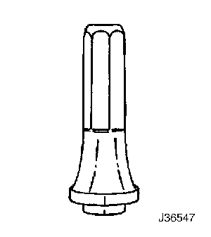
 
| J-36547 Input Shaft
Seal Installer |
DIAGNOSIS
Clutch Operation
Fails to
Release
Checks | Action |
DEFINICIÓN: Cuando se pisa el pedal hasta el suelo, la palanca de cambios no se mueve libremente para entrar y salir de la marcha atrás. |
Check for a loose
linkage. | Repair or replace loose linkage, if necessary. |
Check for a damaged clutch disc. | Replace the damaged clutch disc. |
Check for an improperly installed fork shaft. | Remove and properly reinstalled the fork shaft. Very lightly lubricate the fork fingers at the release bearing with wheel bearing grease. |
Check for the clutch disc hub
binding on the input shaft
splines. | Repair or
replace the clutch disc hub. |
Check for a warped or bent
clutch disc. | Replace the warped or bent
clutch
disc. |
Slipping
Checks | Action |
Check for the driver improperly
operating the vehicle. | Correct the driver's operation
of the vehicle as necessary. |
Check for an oil-soaked clutch
disc. | Correct
the leak at its source and install a new clutch
disc. |
Check for a worn facing or
facing torn from the disc. | Replace the worn disc with a
new disc. |
Check for a warped pressure
plate or a warped flywheel. | Replace the warped pressure
plate or the warped flywheel. |
Check for a weak diaphragm
spring. | Replace
the pressure plate. |
Check for a driven plate that
is not seated. | Start the engine 30 to 40
times. Do not overheat the
engine. |
Check for a driven plate that
is overheated. | Allow the driven plate to
cool. |
Grabbing
(Chattering)
Checks | Action |
Check for a burned or a glazed
facing caused by oil on the
facing. | Correct
the leak at its source and install a new clutch
disc. |
Check for worn splines on the
input shaft. | Replace the worn input
shaft. |
Check for a warped pressure
plate or a warped flywheel. | Replace the warped pressure
plate or the warped flywheel. |
Check for a burned or smeared
resin on the flywheel or the pressure
plate. | Sand off
the burned or smeared resin if it is
superficial. Replace any burned or
heat-checked
parts. |
Rattling
(Transaxle Click)
Checks | Action |
Check for weak retracting
springs. | Replace
the pressure plate. |
Check for a loose release
fork. | Remove
and reinstall the release fork
properly. |
Check for oil in the driven
plate bumper. | Correct the cause of the oil
leak and replace the driven
disc. |
Check for a damaged driven
plate damper spring. | Replace the driven
disc. |
Release Bearing
Noise with Clutch Fully
Engaged
Checks | Action |
Check for the driver improperly
operating the vehicle. | Correct the driver's operation
of the vehicle as necessary. |
Check for a binding release
bearing. | Clean and
re-lubricate the release bearing. Inspect the
release bearing for burrs and
nicks. |
Check for an improperly
installed release lever. | Remove and reinstall the
release lever properly. |
Check for a weak linkage return
spring. | Replace
the weak linkage return
spring. |
Noisy
Checks | Action |
Check for a worn release
bearing. | Replace
the worn release bearing. |
Check for a improperly
installed release lever. | Remove and properly reinstall
the fork shaft. Very lightly lubricate the fork
fingers at the release bearing with wheel
bearing
grease. |
Pedal Stays on
Floor When Disengaged
Checks | Action |
Check for binding in the
linkage or the release bearing. | Lubricate and free-up the
binding linkage or the release
bearing. |
Check for weak pressure plate
springs. | Replace
the pressure
plate. |
Hard Pedal
Effort
Checks | Action |
Check for binding in the
linkage. | Lubricate
and free-up the binding
linkage. |
Check for a worn driven
plate. | Replace
the worn driven
plate. |
COMPONENT
LOCATOR
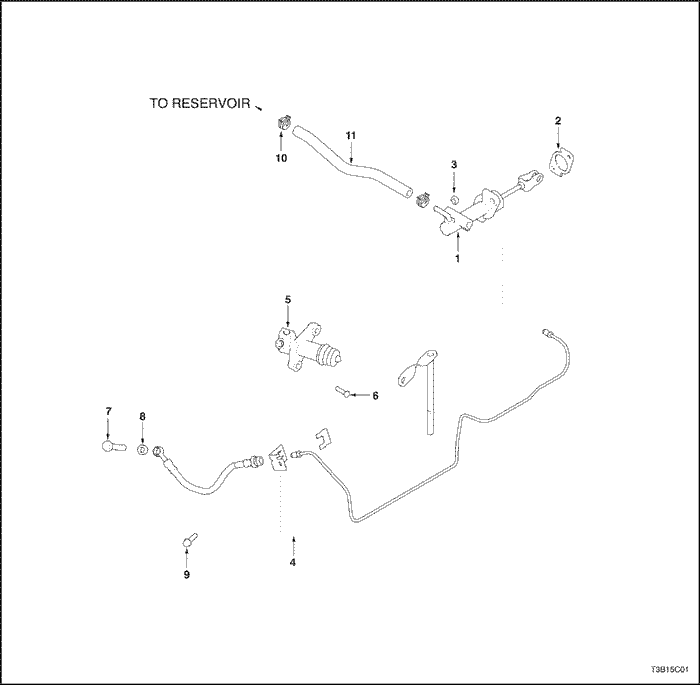
Hydraulic Clutch
- Clutch
Master Cylinder
- Clutch Master Cylinder
Gasket
- Nut
- Clutch Master Cylinder
Pipe
- Clutch Release
Cylinder
- Bolt
- Bolt
- Washer
- Bolt
- Clip
- Reservoir
Tank Hose
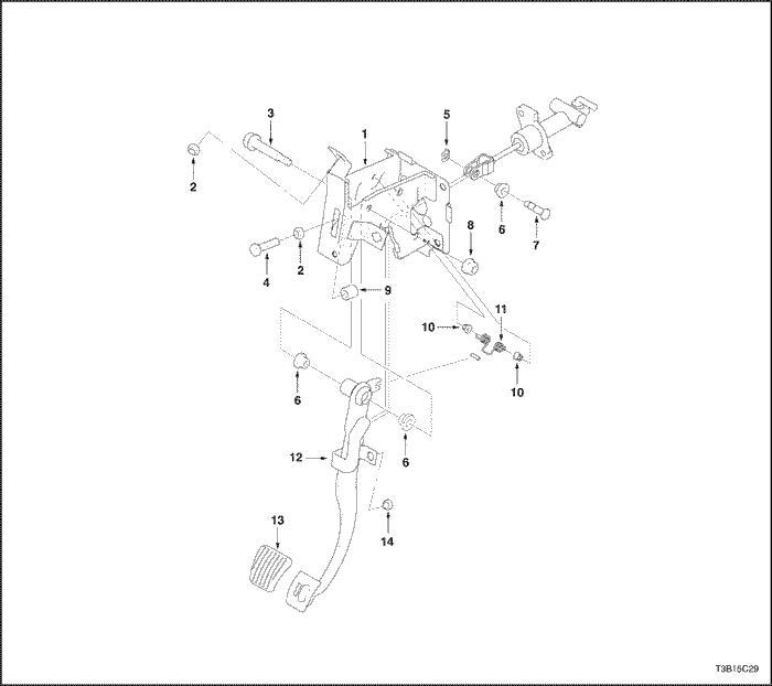
Clutch Pedal
- Clutch
Pedal Brace
- Nut
- Pedal
Shaft
- Bolt
- E-Ring
- Bushing
- Pin
- Nut
- Clutch
Pedal Buffer
- Bushing
- Turn Over
Spring
- Clutch Pedal
- Clutch Pedal
Pad
- Clutch Pedal Buffer
MAINTENANCE AND
REPAIR
ON-VEHICLE
SERVICE
Clutch Pedal
Removal
Procedure
- Disconnect the
negative battery cable.
- Disconnect the return spring
from the clutch pedal.
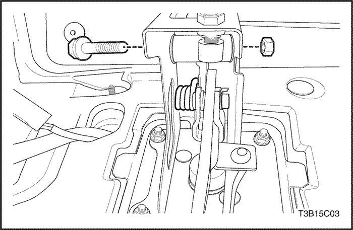
- Remove the nut, the washer,
and the pedal mounting shaft.
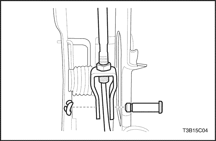
- Remove
the locking clip and push rod fixing pin.
- Remove the
push rod from the clutch pedal.
- Remove the clutch
pedal.
Installation
Procedure
- Install the
clutch pedal.
- Coat the push rod with multi-purpose
grease.
- Install the push rod to the clutch
pedal.
- Install the locking clip and push rod fixing
pin.
- Coat
the pedal mounting shaft with multi-purpose
grease.
- Install the nut, the washer, and the pedal
mounting shaft.
Tighten
Tighten the nut
to 20 N•m (15 lb-ft).
- Connect the
return spring to the clutch pedal.
- Connect the
negative battery cable.
Clutch Pedal
Adjustment (Hydraulic)
Adjustment
Procedure
- Determine the
clutch pedal play. Depress the clutch pedal lightly with
your hand and measure the distance when you feel
resistance.
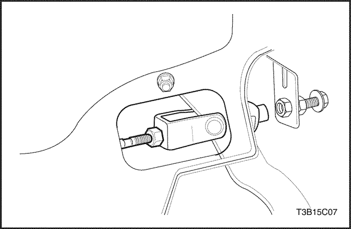
- Adjust
the clutch pedal play. Loosen the locknut and turn the
pushrod. Clutch pedal play should measure 6 to 12 mm (0.2 to
0.5 inch). Tighten the locknut after
adjustment.
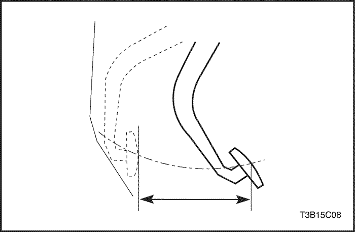
- Measure
the clutch pedal travel. Press the clutch pedal all the way
to the floor. Measure from the starting position to the
ending position.
- Adjust the clutch pedal travel.
Loosen the locknut and turn the bolt. Clutch pedal travel
should measure 125 to 130 mm (4.9 to 5.1 inches). Tighten
the locknut after adjustment.
Clutch Release
Point Adjustment (Hydraulic)
Adjustment
Procedure
- Apply the
parking brake.
- Run the engine at idle
speed.
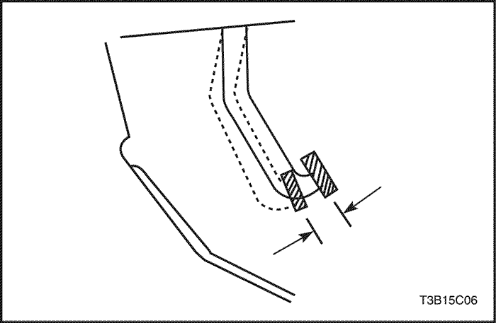
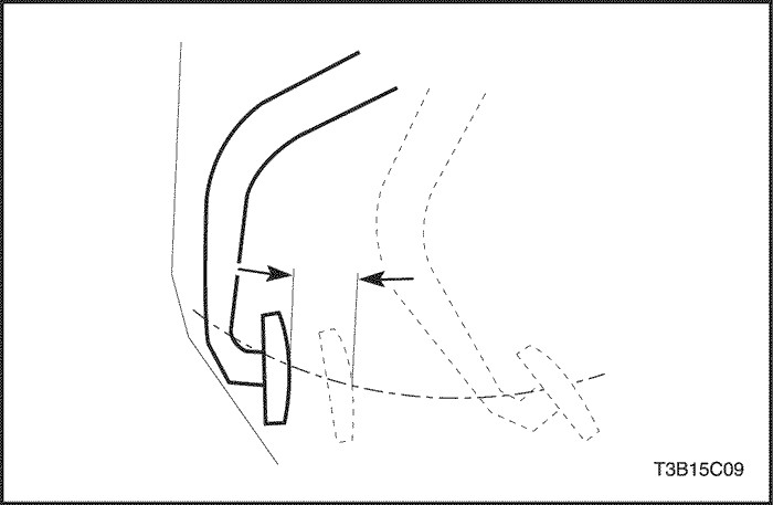
- While you move the shift lever into the
reverse position, depress the clutch pedal slowly and
measure the distance between the point when gear noise is
not heard and the point the clutch pedal is completely
depressed. The distance should be 30 to 35 mm (1.2 to 1.4
inches).
- If the distance is not within the
specified value, check the following:
- Clutch
pedal height
- Clutch pedal play
- Air in
the system
- Clutch cover and disc pressure
plate
Air Bleeding
Bleed the hydraulic system to remove the air
which entered When the pipes were disconnected for repairs.
The clutch/brake fluid in the clutch/brake reservoir must be
maintained at the MIN level or higher during air
bleeding.
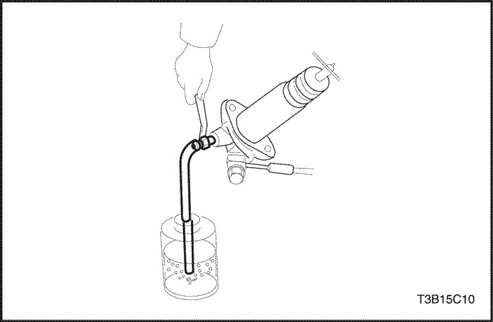
- Attach a vinyl hose to the bleeder plug.
Place the other end of the vinyl tube in a glass container
half-filled with brake fluid.
- Slowly pump the clutch
pedal several times.
- While you press the clutch
pedal, loosen the bleeder screw until the fluid starts to
run out. Close the bleeder screw.
- Repeat Step 3
until there are no air bubbles in the fluid.
- Fill
the reservoir with brake fluid up to the MAX
level.
Pressure Plate and
Clutch Disc
Removal
Procedure
- Disconnect the
negative battery cable.
- Remove the transaxle from
the vehicle. Refer to Section 5B1,
Five-Speed Manual Transaxle
(D16).
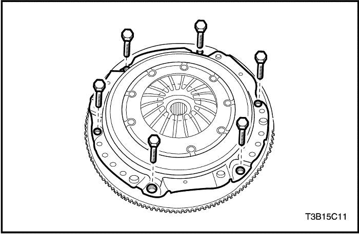
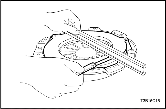
- Remove the pressure plate
bolts and the pressure plate.
Important : Support the pressure plate
when you remove the last
bolt.
- Remove
the clutch disc from the
flywheel.
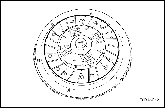
Inspection Procedure – Clutch
Disc
- Visual
Inspection
- Inspect the worn or oily
contamination on the clutch surface.
- Inspect the
damaged or weakened torsion spring.
- Inspect the
a warped or bent clutch disc. After inspection, replace
new clutch disc, if necessary.
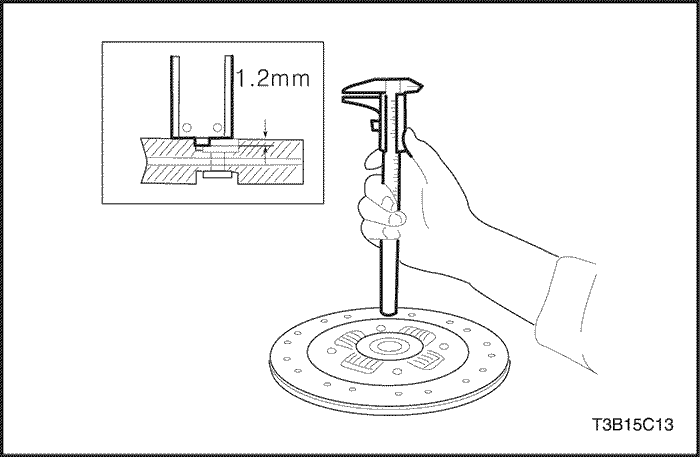
- Clutch
Disc Inspection
- Measure the rivet head depth
from the clutch disc surface.
- Replace the clutch
disc if the measured value is below the
limit.
- Rivet Head Depth (Limit) : 1.2 mm (0.047
in)
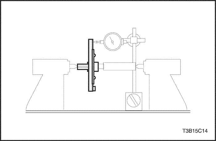
- Clutch
Disc Runout in Rotational Direction
Inspection
- Measure runout using the dial
gauge.
- If runout exceeds limit, replace the
clutch disc.
Inspection Procedure
– Pressure Plate
- Check
for a worn diaphragm spring finger.
- Check for a worn
or cracked pressure plate surface.
- Check for the
polluted face by the oil. After inspection, replace the
pressure plate if necessary.
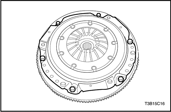
Installation
Procedure
- Coat the
spline on the clutch disc with multi-purpose
grease.
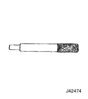
- Align the pressure plate and the clutch disc
onto the flywheel using the clutch arbor
J-42474.
- Install the pressure plate
bolts.
Tighten
Tighten the
bolts to 15 N•m (11 lb-ft).
- Remove
the clutch arbor J-42474.
- Install the transaxle into
the vehicle. Refer to Section 5B1,
Five-Speed Manual Transaxle
(D16).
- Connect the negative battery
cable.
Clutch Master
Cylinder Assembly
Removal
Procedure
Before disconnecting the reservoir tank hose,
remove the clutch/brake fluid from the reservoir
tank.
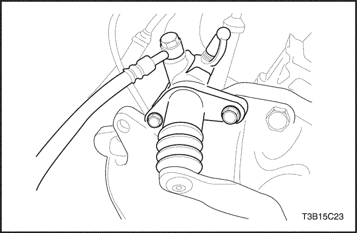
- Remove the locking clip.
- Remove the
push rod fixing pin and push rod.
- Disconnect
the hose clamp on the master cylinder.
- Disconnect
the master cylinder hose.
- Remove
the master cylinder pipe.
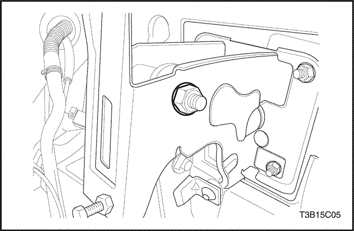
- Remove
the clutch master cylinder nuts.
- Remove the clutch
master cylinder.
Installation
Procedure
- Install the
clutch master cylinder and clutch master cylinder
nuts.
Tighten
Tighten the
clutch master cylinder nuts to 22 N•m (16
lb-ft).
- Install
the master cylinder pipe.
- Connect
the master cylinder hose.
- Connect the hose clamp on
the master cylinder.
- Install
the push rod fixing pin and push rod.
- Install the
locking clip.
- Bleed the air. Refer to "Air Bleeding" in
this section.
- Adjust the clutch pedal. Refer to
"Clutch Pedal Adjustment" in this
section.
- Fill the reservoir with clutch/brake fluid
up to the MAX level.
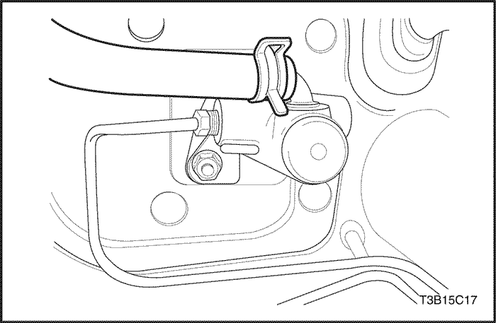
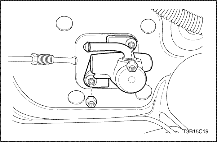
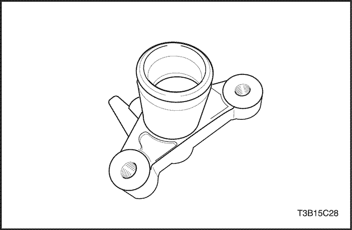
Clutch Release
Cylinder Assembly
Removal
Procedure
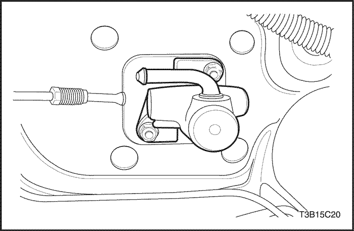
- Remove the bolt
and disconnect the hose from the clutch release cylinder.
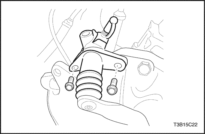
- Remove
the clutch release cylinder bolts and remove the release
cylinder from the transaxle.
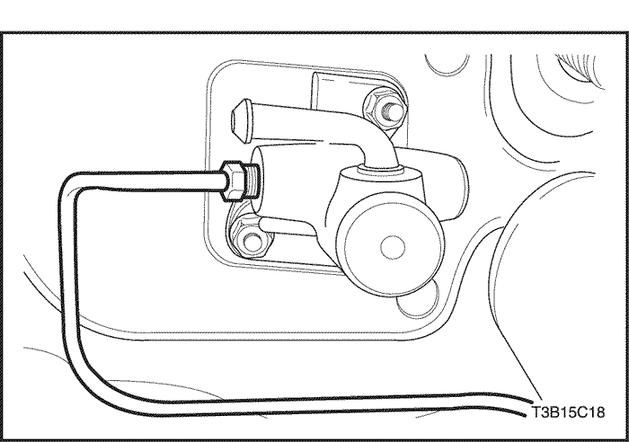
Installation
Procedure
- Connect the
release cylinder to the transaxle and install the
bolts.
Tighten
Tighten the
release cylinder bolts to 20 N•m (15
lb-ft).
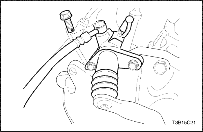
- Connect
the hose assembly to the cylinder body.
- Apply grease
where the pushrod connects to the release lever. Be careful
not to stain the boot.
- Bleed the air. Refer to "Air Bleeding" in
this section.
- Adjust the clutch pedal. Refer to "Clutch Pedal Adjustment (Hydraulic)"
in this section.
- Fill the reservoir with
clutch/brake fluid up to the MAX level.
UNIT
REPAIR
Clutch Master
Cylinder
Disassembly
Procedure
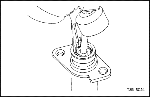
- Remove the
clutch master cylinder assembly from the vehicle. Refer to
"Clutch Master Cylinder Assembly"in
this section.
- Remove the boot and disconnect the
piston stop ring using ring pliers.
- Remove
the pushrod assembly and the piston
assembly.
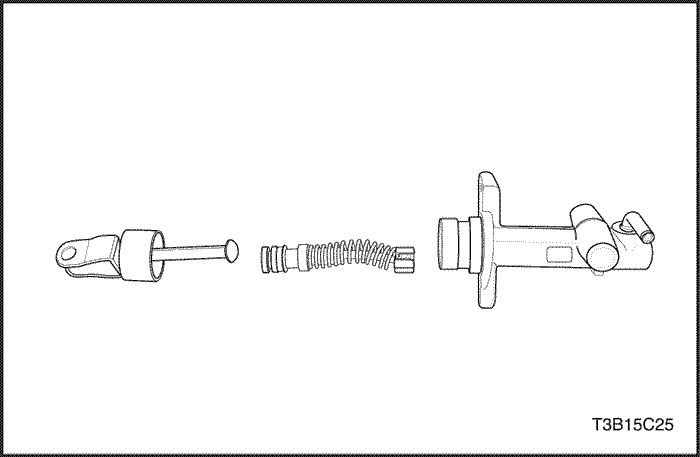
- Inspect the clutch master cylinder wall
and the piston for wear. Replace the piston if
necessary.
- Inspect the cup and the piston for wear.
Fluid leaks will show wear on the cup and the piston.
Replace the cup and the piston if necessary.
- Inspect
the pushrod for wear. Repair the pushrod if
necessary.
Assembly
Procedure
- Apply clean
fluid to the piston assembly cup and insert the piston
assembly and the pushrod assembly into the master cylinder
body.
- Install
the piston stop ring using ring pliers. Install the
boot.
- Install the clutch master cylinder assembly
into the vehicle. Refer to "Clutch Master Cylinder Assembly"in
this section.
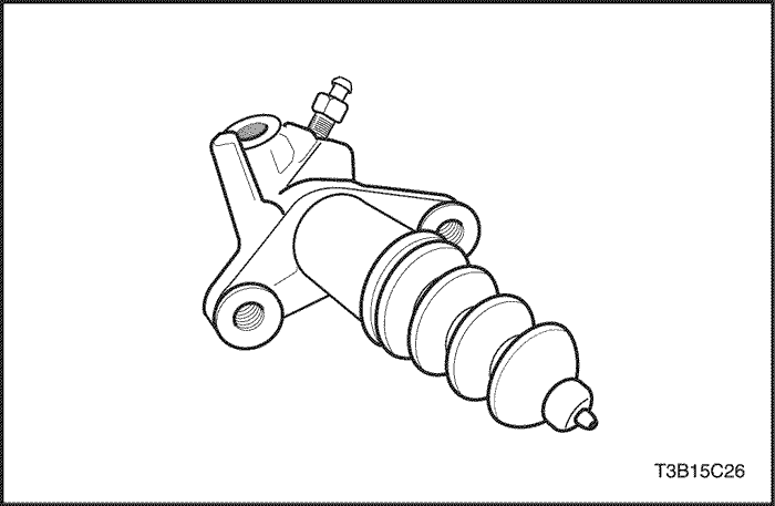
Clutch Release
Cylinder
Disassembly
Procedure
- Remove the
clutch release cylinder assembly from the vehicle. Refer to
"Clutch Release Cylinder Assembly"
in this section.
- Remove the bolts and
brackets.
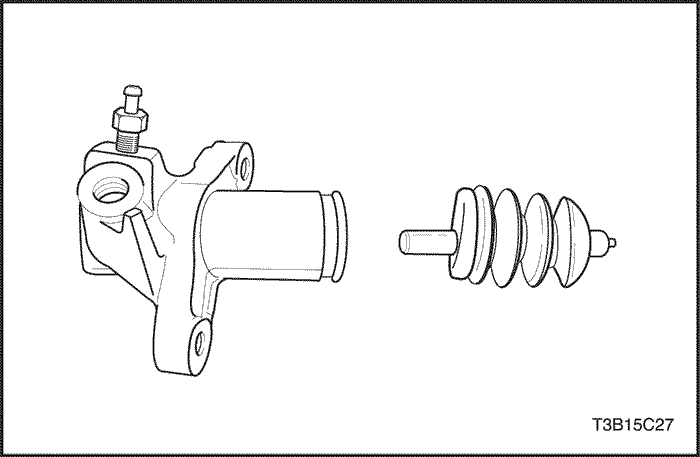
- Remove
the boot and the pushrod.
- Compress
the piston with a driver and remove the snap ring with snap
ring pliers.
- Remove the piston
assembly.
Assembly
Procedure
- Apply clean
clutch fluid to the piston and the cup.
- Install the
spring to the piston, and insert the assembly into the
cylinder body.
- Compress the piston with a driver,
then install the snap ring with snap ring
pliers.
- Install
the pushrod and the boot.
- Install
the brackets and the bolts.
- Install the clutch
release cylinder assembly. Refer to "Clutch Release Cylinder Assembly"
in this section.
GENERAL DESCRIPTION AND SYSTEM
OPERATION
Driving Members
The
driving members consist of two flat surfaces machined to a
smooth finish. One of these is the rear face of the engine
flywheel and the other is the pressure plate. The pressure plate
is fitted into a steel cover which is bolted to the
flywheel.
Driven Members
The driven member is the clutch disc
with a splined hub.The splined hub is free to slide lengthwise
along the splines of the input shaft and drives the input shaft
through these same splines.
The driving and driven members are held in contact
by spring pressure. This pressure is exerted by a diaphragm
spring in the pressure plate assembly.
Operating Members
The
clutch release system consists of the clutch pedal, the clutch
shaft, the fork, and the release bearing. When pressure is
applied to the clutch pedal, the fork pivots on its shaft and
the inner end pushes against the release bearing. The bearing
then pushes against the release levers in the pressure plate
assembly, thereby releasing the
clutch.