SECTION 5
ELECTRICAL WIRING DIAGRAMS
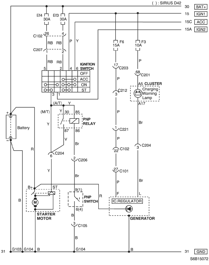
1. STARTING & CHARGING SYSTEM
1) BATTERY, IGNITION SWITCH, STARTER MOTOR, GENERATOR & PNP SWITCH CIRCUIT
a. CONNECTOR INFORMATION
CONNECTOR NO
(PIN NO, COLOR) | CONNECTING WIRING HARNESS | CONNECTOR POSITION |
| C101 (32 Pin, Black) | Engine - Engine Fuse Block | Engine Fuse Block |
| C102 (32 Pin, Gray) | Front - Engine Fuse Block | Engine Fuse Block |
| C201 (76 Pin, Black) | I.P - I.P Fuse Block | I.P Fuse Block |
| C202 (20 Pin, White) | I.P - I.P Fuse Block | I.P Fuse Block |
| C204 (18 Pin, Gray) | I.P - Engine | Upper Co-Driver Leg Room |
| C206 (10 Pin, White) | TCM - I.P | Below TCM |
| C207 (4 Pin, Black) | Front - I.P | Below I.P Fuse Block |
| C212 (15 Pin, Blue) | I.P - Floor | Below I.P Fuse Block |
| C221 (11 Pin, Blue) | Front - Floor | Under Left A Pillar |
| G103 | Battery | Below ECM |
| G104 | Battery | Next to Start Motor |
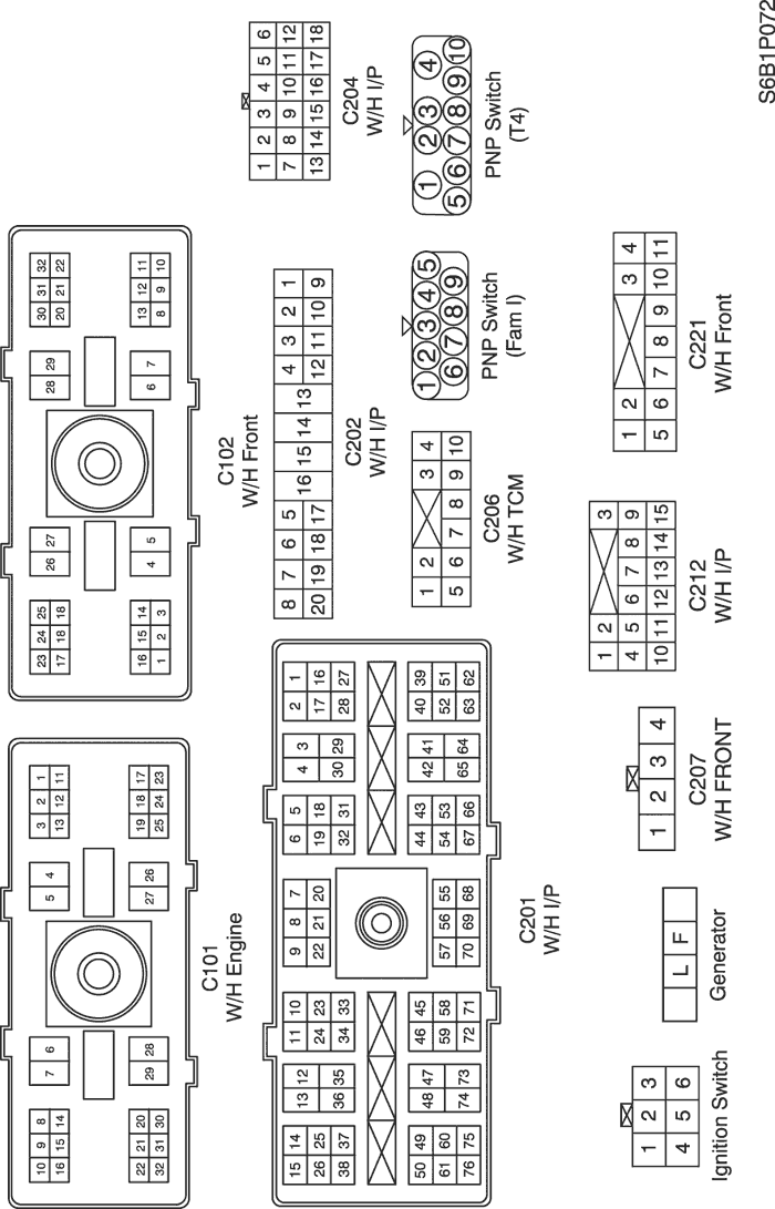
b. CONNECTOR IDENTIFICATION SYMBOL & PIN NUMBER POSITION
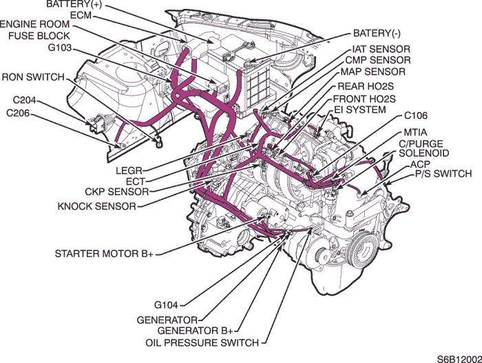
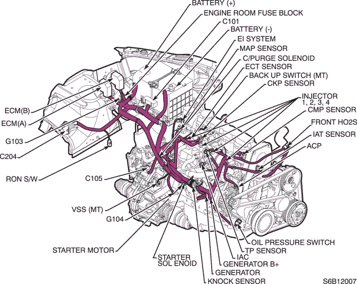
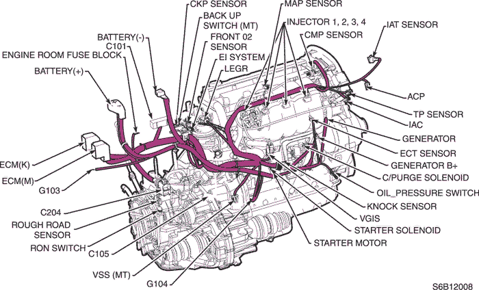
c. POSITION OF CONNECTORS AND GROUNDS
| © Copyright Chevrolet Europe. All rights reserved |