UNIT
REPAIR
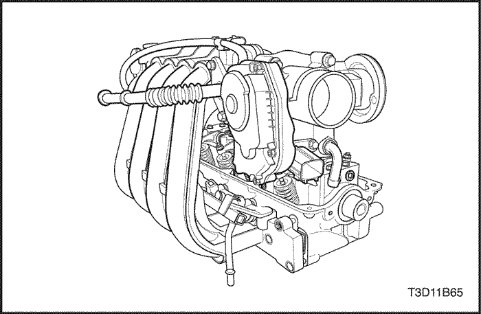
Cylinder Head and
Valve Train Components
Tools
Required
09916-14510 Valve Spring Compressor
09916-37320 Valve Guide Reamer
09916-38210 Valve Guide Reamer
09916-44910 Valve Guide
Remover
09916-48210 Valve
Spring Compressor Attachment
09916-58210 Valve Guide Installer
09917-88220 Valve Guide Installer
Attachment
KM 412 Engine
Overhaul Stand


Disassembly
Procedure
- Remove the cylinder
head with the intake manifold and the exhaust manifold attached.
Refer to "Cylinder Head and Gasket"
in this section.
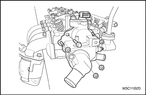
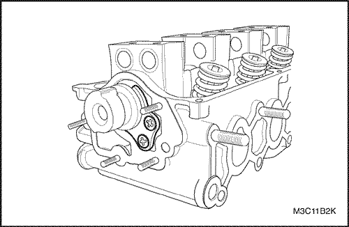
- Remove the bolt and the nuts in the
water outlet case .
- Remove the water outlet
case.
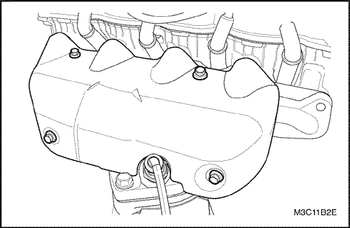
- Remove the
exhaust manifold heat shield bolts.
- Remove the exhaust
manifold heat shield.
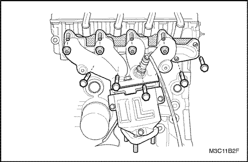
- Remove the
exhaust manifold nuts and the bolts.
- Remove the exhaust
manifold gasket.
- Remove the exhaust manifold
studs.
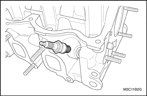
- Remove the
spark plugs.
- Remove the
intake manifold retaining bolts and the nuts.
- Remove the
intake manifold with the gasket.
- Remove the intake
manifold studs.
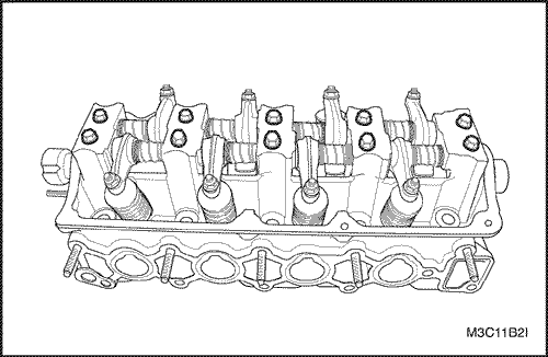
- Remove the
rocker arm shaft mounting bolts.
- Remove the
rocker arm spring and the rocker arm.
- Remove the
screws with the camshaft thrust plate.
- Remove the
camshaft.
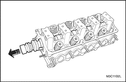
- Remove the
camshaft front oil seal from housing hole.
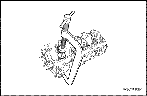
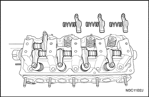
- Using the
valve spring compressor 09916-14510, compress the valve
spring
- Remove the valve keepers.
- Remove the
valve spring retainer and valve spring.
- Remove the
valves.
- Remove the
valve stem oil seals.
- Remove the valve spring
seat.
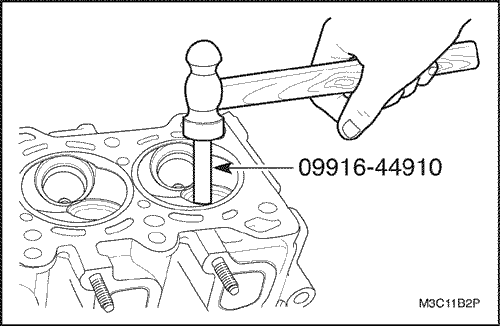
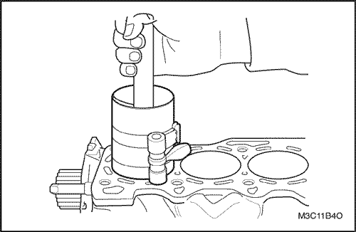
- Position
the valve guide remover 09916-44910 on the valve
guide.
- Hammer and remove the valve guide from the
combustion chamber to the direction of the installed valve
spring using the valve guide remover 09916-44910.
- Remove
the valve guide.
Cylinder Head
Inspection
- Clean the sealing
surfaces.
- Inspect the cylinder head gasket and the
mating surfaces for leaks, corrosion, and
blowby.
- Inspect the cylinder head for
cracks.
- Inspect the length and the width of the cylinder
head using a feeler gauge and a straight edge.
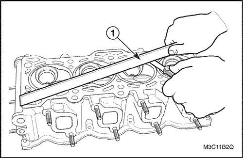
- Check the
sealing surfaces for deformation and warpage. The cylinder head
sealing surfaces must be flat with in 0.05mm (0.0020 in.)
maximum.
- Inspect all
threaded holes for damage.
- Inspect the valve seats for
excessive wear and burned spots.
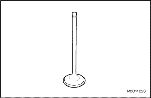
Valve
Inspection
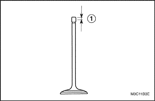
- Inspect valve stem
tip wear.
- Inspect the valve keeper grooves and oil seal
grooves for chips and wear.
- Inspect the valves for burns
or cracks.
- Inspect the valve stem for burrs and
scratches.
- Inspect the valve stem. The valve stem must
be straight.
- Inspect the valve facefor grooving. If the
groove is so deep the refacing would result in a sharp edge,
replace the valve.
- Inspect the
valve spring. If the valve spring ends are not parallel, replace
the valve spring.
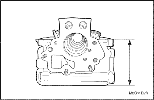
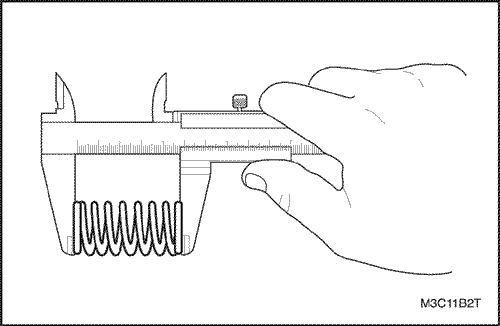
- Measure the valve spring height.
Refer to "Engine Specifications" in
this section. If the valve spring height does not match the
specifications, replace the valve spring.
- Inspect the
valve spring seating surface of the valve rotators for wear or
gouges. Replace as required.
Cleaning
Procedure
- Clean the cylinder
head.
- Clean the valve guides.
- Clean all of the
threaded holes.
- Clean the valves of carbon, oil and
varnish.
Cylinder Head
Overhaul
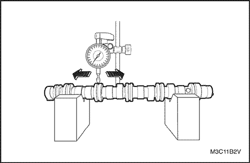
Measuring The Camshaft
Bend
- Measure the bending of the camshaft
using a dial gauge and replace it when the measured value is
over the specified limit (0.03mm (0.0012
in.)).
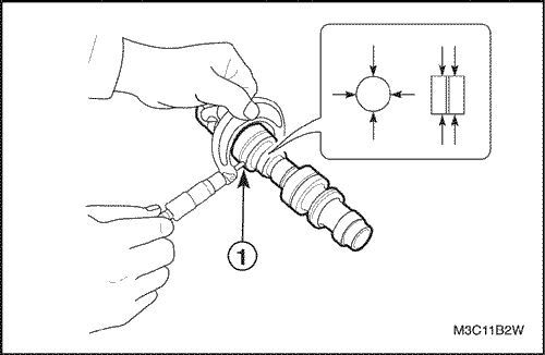
Abrasion of The Camshaft
Journal
- Measure the outer
diameter of each journal at the 5 different
places.
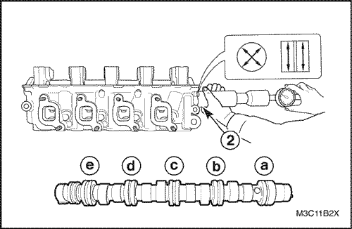
- Using a
bore gauge, measure the inner diameter of the cylinder head
jornal at the 5 places (The clear-ance of journal is measured by
the difference be-tween the outer diameter of camshaft journal
and inner diameter of cylinder head journal
part.)
- Replace the camshaft (or cylinder head, if
necessary) of which limit is over the specified
limit.
Item | Standard | Limit |
Journal Clearance | 0.05-0.091
mm (0.0020-0.0036
inches) | 0.15
mm (0.0059
inches) |
Item | Outer
diameter, camshaft
journal | Inner
diameter cylinder head journal
part |
a | 43.425-43.450
mm (1.7096-1.7106 in.) | 43.500-43.516
mm (1.7126-1.7132
in.) |
b | 43.625-43.650
mm (1.7175-1.7185 in.) | 43.700-43.716
mm (1.7205-1.7211
in.) |
c | 43.825-43.850
mm (1.7254-1.7264 in.) | 43.900-43.916
mm (1.7283-1.7290
in.) |
d | 44.025-44.050
mm (1.7333-1.7343 in.) | 44.100-44.116
mm (1.7362-1.7369
in.) |
e | 44.225-44.250
mm (1.741-1.742 in.) | 44.3-44.316
mm (1.744-1.745
in.) |
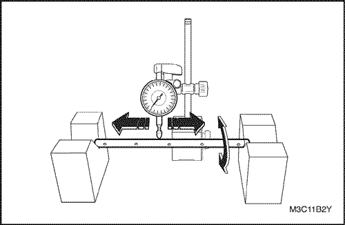
Bending of The Rocker
Arm Shaft
- Check the bending
of the rocker arm shaft by using the V block and dial
gauge.
- Replace the rocker arm shaft of which bending is
over the specification (0.10mm (0.0039
inches)).
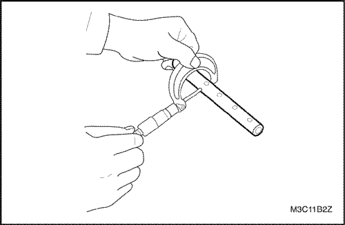
Clearance Between The
Rocker Arm and The Rocker Arm
Shaft
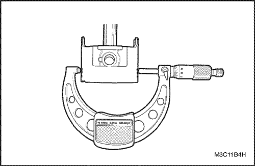
- Check the outer
diameter of the rocker arm shaft using a
micrometer.
- Check the
inner diameter of the rocker arm using a bore
gauge.
- Replace the shaft or rocker arm (or both of them,
if necessary) if the difference is over the limit between the
outer diameter and the inner diameter (0.005 - 0.040mm (0.0002 -
0.0016 in.)
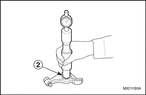
Clearance Between The
Valve Stem and The Valve
Guide
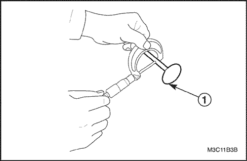
- Check the outer
diameter of the valve stem using a
micrometer.
- Intake : 5.465 - 5.480mm (0.2152 -
0.2157 in.)
- Exhaust : 5.440 - 5.455mm (0.2142 -
0.2148 in.)
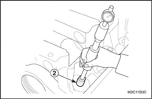
- Check the
inner diameter of the valve guide using a bore gauge (at least 1
place in the direction to valve length)
- Intake :
5.500 - 5.512mm (0.2165 - 0.2170 in.)
- Exhaust :
5.500 - 5.512mm (0.2165 - 0.2170 in.)
- Check the
clearance between the valve stem and the valve
guide
- Intake : 0.020 - 0.047mm (0.0008 - 0.0019
in.)
- Exhaust : 0.0045 - 0.072mm (0.0018 - 0.0028
in.)
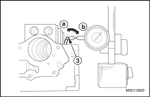
- If a bore
gauge is not available, measure the clearance using a dial gauge
by moving the edge of the stem to the
directions.
- Intake : 0.14mm (0.0055
in.)
- Exhaust : 0.18mm (0.0071
in.)
- Replace the valve stem or valve guide, if
the measured valve is over the limit.
Valve
- Inspect the
valve. Refer to Valve Inspection in this section.
- Check
the valve or stem for abrasion, burn or bending, and replace as
necessary.
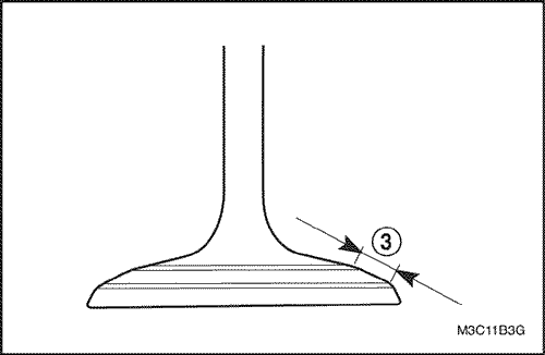
- Abrasion of the valve edge.
- Check
the edge of each valve for abrasion. Some uneven abrasion
would be made on the edge because the rocker arm gets
contacted at this surface when operating. Repair the section
within 0.05mm (0.002 in.) as required, or replace the valve
if some modification is required more than
that.
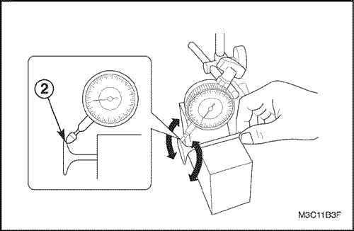
- Deviation
to the rotating direction. Measure the deviation to the rotating
direction using a dial gauge and the V block by turning the
valve slowly. Deviation limit of valve head to the rotating
direction within 0.08mm (0.0031 in.)
- Replace valve, if
the measured value exceeds the limit.
- Clean the
valve and the valve seat and apply red stamping ink thinly to
the contacting surface of the valve seat. Check the fitness
after installing the valve unit.
- Check the contact
witdth on the surface of the valve seat.
- Intake :
1.46 - 1.66mm (0.0575 - 0.0654 in.)
- Exhaust : 1.46 -
1.66mm (0.0575 - 0.0654 in.)
- Repair by
grinding and cutting off the valve seat, and lap it if its
contacting width is not even or out of the
specified.
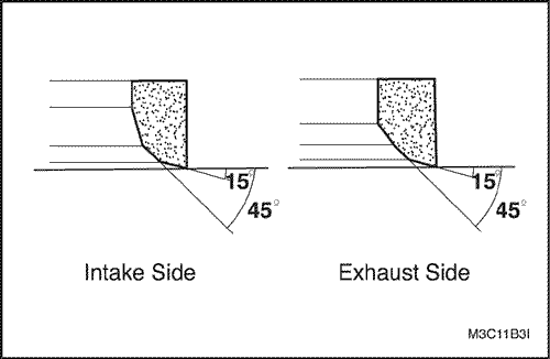
- Upon applying a seat cutter, use the one of
smaller angle first and increase the angle of the using cutter
up to the light and final modification of the contact. And
finish contact surface and its location with the cutter of 45
degrees.
Important : Upon
cutting, take care of the contact width. Finish the
cutting with gradually reduced power for no cutting mark
on the surface.
- Make
lapping in two stages, first with normal lap and second with
fine one for the both sides.
Assembly
Procedure
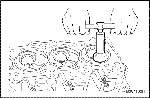
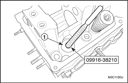
- Make the valve
guide hole using a valve guide reamer 09916-38210. Before
Installing The new valve guide into the cylinder head, ream
guide hole with 11mm reamer to remove burrs. Make sure that the
guide hole cones to a complete roundness
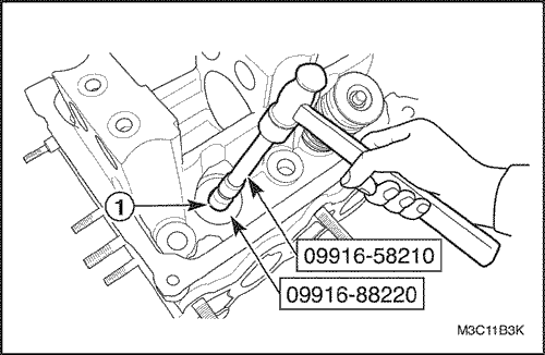
- Peen and
install new valve guide
Caution : Heat the cylinder head
uniformly at a temperature 80-100°C (176-212°F) not
to make the head deformed, and drive new valve guide
completely into the hole with the tools the valve
guide installer attachment
09917-88220.
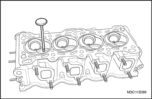
- Check
the protruded part of the guide from the cylinder
head.
Important : Do not
reuse the valve guide once disassembled, replace it with
the new oversized valve
guide.
- Valve guide
oversize : 0.03mm (0.0012 in.)
- Valve guide
protrusion : 14mm (0.5512 in.)
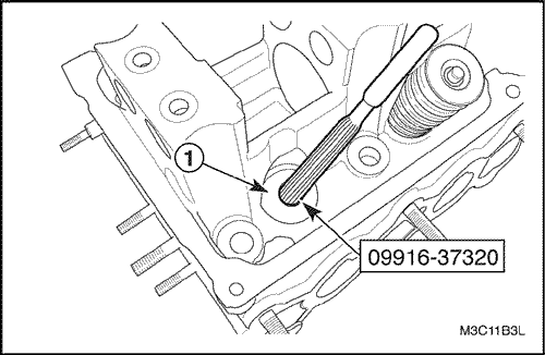
- Repair the
valve guide bore with the valve guide reamer 09916-37320 (5mm or
0.1969 in.)
- Make the hole free from foreign
material.
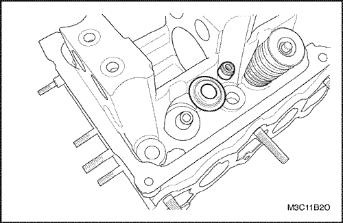
- Install the
valve spring seats.
- Install the valve stem oil seal to
the valve guide. After applying engine oil to seal and
installing seal to the valve guide and make sure that seal is
properly fixed to the valve guide.
Important : Do not reuse the disassembled
oil seal and replace it with new one. When installing
it, neer tap or hit tool with a hammer or else. Install
seal to guide only by pushing special tool with hand.
Tapping or hitting tool may cause damage on
seal.
- Install the
valve to the valve guide.
Important : Before installing it, coat
engine oil to the stem seal, valve guide bore and valve
stem.
- Install the
valve springs and the spring retainers.
- Using the valve
spring compressor 09916-48210, compress the valve
spring
- Install the valve keepers.
- Install the
camshaft front oil seal from housing hole.
- Coat the
engine oil to the camshaft front oil seal, the cam, and the
camshaft journal.
- Install the camshaft front oil seal to
the housing hole.
- Install the camshaft to the cylinder
head.
Notice :
Installing the camshaft, take extreme care to prevent
any screatch, nick or
damage.
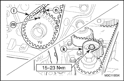
- Install the
screws with the camshaft thrust plate.
Tighten
Tighten the screws to 10 N•m (89
lb-in).
- Coat the
engine oil to the rocker arms and the rocker rocker arm
shafts.
- Install the rocker arm spring and the rocker
arm.
- Install the
rocker arm shaft mounting bolts.
Tighten
Tighten the bolts to 10 N•m (89
lb-in).
Important : Rocker arm shaft for the intake
valves and the exhaust valves are different and their
directions of installation are
different.
- Install the
intake manifold studs.
- Install the intake manifold with
the gasket.
- Install the intake
manifold.
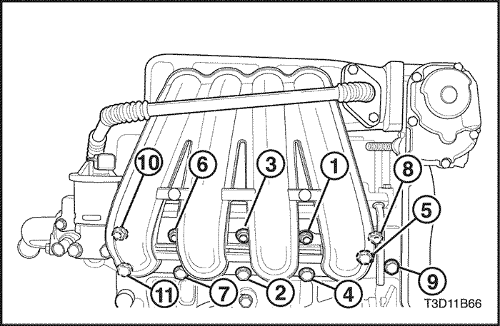
- Install the
intake manifold nuts in the sequence order.
Tighten
- Tighten the
intake manifold nuts and the bolts to 17 N•m (13
lb-ft).
- Tighen the intake manifold supprot bracket
bolt to 10 N•m (89 lb-in).
Important : Before tightening the intake
manifold nuts, first of all, tighten the intake manifold
support bracket nut.
- Install the
spark plugs.
- Install the
exhaust manifold gasket and the exhaust
manifold.
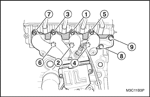
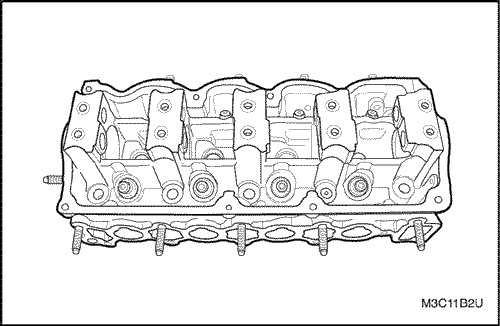
- Install the
bolts and nuts in the sequence order as shown in the
picture.
Tighten
Tighten the exhaust manifold nuts
and bolts to 22 N•m (16 lb-ft).
- Install the
exhaust manifold heat shield.
- Install the exhaust
manifold heat shield bolts.
Tighten
Tighten the exhaust manifold heat
shield bolts to 10 N•m (89
lb-in).
- Install the
water outlet case.
- Install the water outlet case
mounting bolts.
Tighten
Tighen the water outlet case
mounting bolts to 10.5 N•m (93
lb-in).
- Install the cylinder head with
the intake manifold and exhaust manifold attached. Refer to "Cylinder Head and Gasket"
in this section.
Crankshaft
Tools
Required
KM-412
Engine Overhaul Stand
09916-77310 Piston
Compressor
Disassembly
Procedure
- Removethe engine.
Refer to "Engine"in this
section.
- Remove the transaxle from the engine. Refer to
Section 5B,
Five-Speed Manual Transaxle.
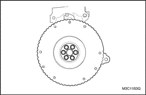
- Remove the
flywheel bolts.
- Remove the flywheel.
- Mount the
engine assembly on the engine overhaul stand
KM-412.
- Remove the
cylinder head. Refer to "Cylinder Head and Gasket"
in this section.
- Drain the engine oil from the
engine.
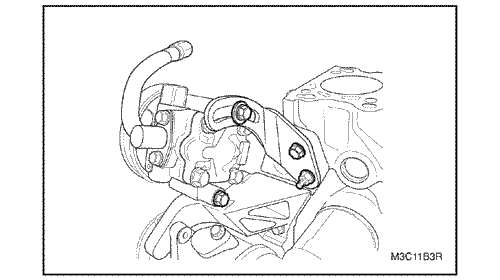
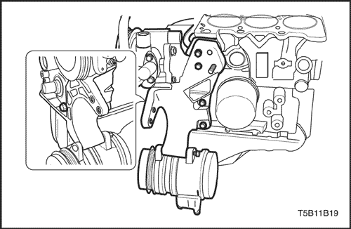
- Remove the power steering adjusting
bolts.
- Remove the power steering/air conditioning
belt.
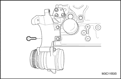
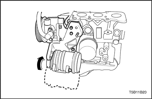
- Turn the
A/C compressor downward.
- Remove the A/C compressor/power
steering bracket bolts.
- Remove the A/C compressor/power
steering bracket.
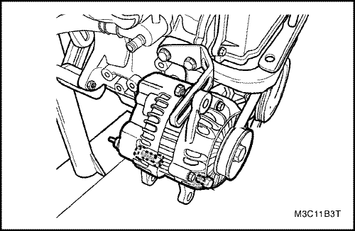
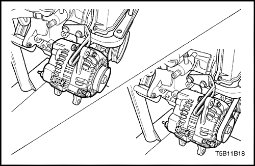
- Loosen the
generator bolt.
- Loosen the generator lower bolts and the
nut.
- Remove the generator and belt.
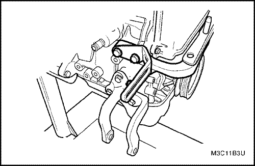
- Loosen the
engine mount upper bracket bolts.
- Remove the generator
shackle.
- Remove the upper bracket.
- Loosen the
engine mount lower bracket bolts.
- Remove the lower
bracket.
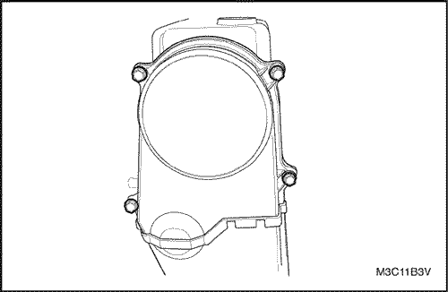
- Remove the
upper timing belt cover bolts.
- Remove the upper timing
belt cover.
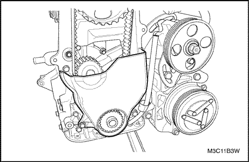
- Remove the
lower timing belt cover bolts.
- Remove the lower timing
belt cover.
- Loosen the
timing belt automatic tensioner bolt.
- Remove the
automatic tensioner from the timing belt.
- Remove the
timing belt.

- Rotate the
engine on the engine overhaul stand KM-412.
- Remove the
oil pan retaining bolts and the nuts.
- Remove the oil
pan.
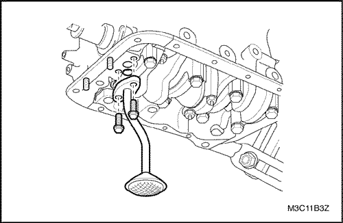
- Remove the
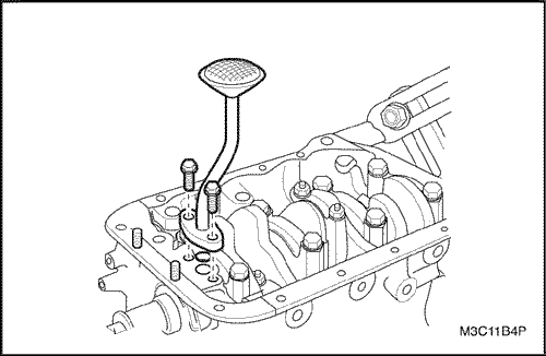
oil pan pickup tube bolts.
- Remove the oil pan pickup
tube.
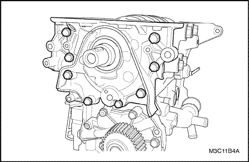
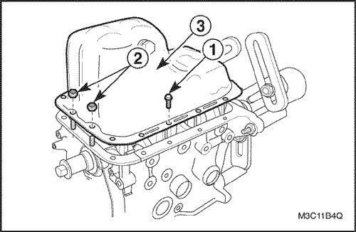
- Remove the
oil pump retaining bolts.
- Remove the oil
pump.
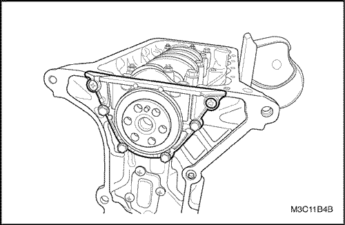
- Remove the
crankshaft rear oil seal housing screws and
bolts.
- Remove the gasket and the oil seal
housing.
- Mark the
order of the rod bearing caps.
- Remove the connecting rod
cap nuts for all of the pistons.
- Remove the connecting
rod bearing caps and the lower connecting rod
bearing.
- Remove the upper connecting rod
bearing.
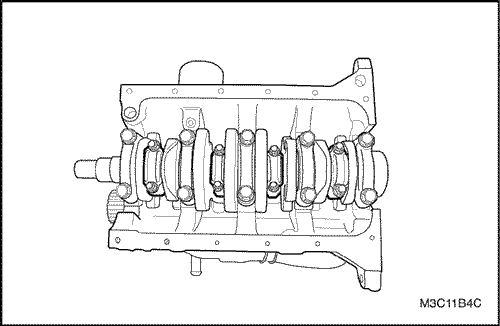
- Mark the
order of the crankshaft bearing caps.
- Remove the
crankshaft bearing cap bolts.
- Remove the crankshaft
bearing cap.
- Remove the crankshaft bearings from the
crankshaft bearing caps.
- Remove the crank
shaft.
- Remove the crankshaft bearings from the engine
block.
- Clean the parts, as
necessary.
Assembly
Procedure
- With crankshaft and
bearings in place, plastic gauge all bearing clearances. Refer
to "Crankshaft Bearings and Connecting Rod Bearings - Gauging Plastic"
in this section.
- Inspect the crankshaft end play
with the crankshaft bearings installed.
- Check the
Permissible crankshaft end play. Refer to "Engine Specifications" in
this section.
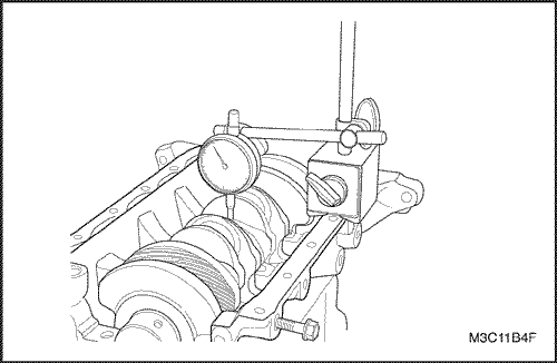
- With the
crankshaft mounted on the front and the rear crankshaft
bearings, Check the middle crankshaft journal for permissible
out-of-round (runout). Refer to "Engine Specifications" in
this section.
- Coat the
crankshaft bearings with engine oil.
- Apply a bead of
adhesive sealing compound to the grooves of the rear crankshaft
bearing cap.
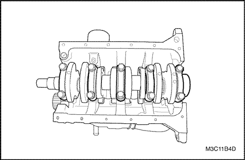
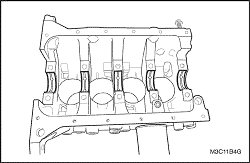
- Install the crankshaft bearings in the
engine block.
- Install the crankshaft.
Important : Grease the crankshaft journals
and lubricate the crankshaft bearings slightly so that
the plastic gauging thread does not tear when the
crankshaft bearing caps are
removed.
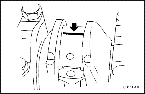
- Inspect all of the
crankshaft bearing clearances using a commercially available
plastic gauging (ductile plastic threads).
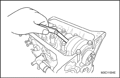
- Cut the
plastic gauging threads to the length of the bearing width. Lay
them axially between the crankshaft journals and the crankshaft
bearings.
- Install the
crankshaft bearings to the crankshaft bearing
caps.
- Install the crankshaft bearing caps
bolts.
Notice :
Do not reuse the old crankshaft bearing cap bolts.
Damage to the engine could
result.
Tighten
Tighten the crankshaft bearing cap
bolts to 57 N•m (42 lb-ft).
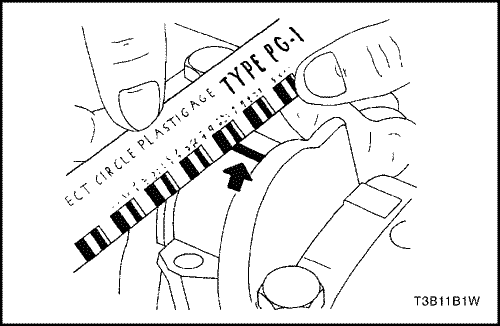
- Remove the
crankshaft bearing caps.
- Measure the width of the
flattened plastic thread of the plastic gauging using a ruler.
(Plastic gauging is available for different tolerance
ranges.)
- Inspect the bearing clearances for permissible
tolerance ranges. Refer to "Engine Specifications" in
this section.
Inspection Precedure -
Connecting Rods
- Coat the
connecting rod bearings with engine
oil.
Important : Grease
the connecting rod journals and lubricate the connecting
rod bearings slightly so that the plastic gauging thread
does not tear when the connecting rod bearing caps are
removed.
- Install the upper
connecting rod bearings into the connecting rod
journals.
- Install the lower connecting rod bearings into
the connecting rod bearing caps.
- Inspect all of the
connecting rod bearing clearances using a commercially available
plastic gauging (ductile plastic threads).
- Cut the
plastic gauging threads to the length of the bearing width. Lay
them axially between the connecting rod journals and the
connecting rod bearing.
- Install the connecting rod
bearing caps.
- Install the connecting rod bearing cap
nuts.
Tighten
Tighten the
connecting rod bearing cap nuts to 33 N•m (24
lb-ft).
- Remove the
connecting rod bearing caps.
- Measure the width of th
flattened plastic thread of the plastic gauging using a ruler.
(Plastic gauging is available for different tolerance
ranges.)
- Inspect the bearing clearance for permissible
tolerance ranges. Refer to "Engine Specifications" in
this section.
Inspection Precedure -
Piston
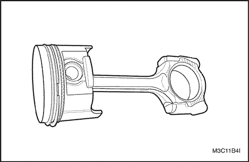
- Inspect the connecting
rod for bending or twisting. If the connecting rod is bent or
twisted, replace the connecting rod.
- Inspect the
connecting rod bearings.
- Inspect the connecting rod
lower end for wear.
- Inspec the connecting rod upper end
for scoring.
- Inspect the piston for scoring, cracks and
wear.
- Inspect pistion for taper using a
micrometer.
- Inspect the
piston for fit to the connecting rod.
- Inspect the
engine block deck surface for flatness using a straight edge and
a feeler gauge. Refer to "Engine Specifications" in
this section.
- Inspect the bearing bore for concentricity
and alignment using a bore gauge. Refer to "Engine Specifications" in
this section.
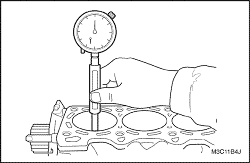
- Inspect the engine block cylinder bore for
wear, runout ridging and taper using a bore gauge. Refer to "Engine Specifications" in
this section.
- Inspect the engine block cylinder bore for
glazing. Lightly hone the cylinder bore as
necessary.
Installation
Procedure
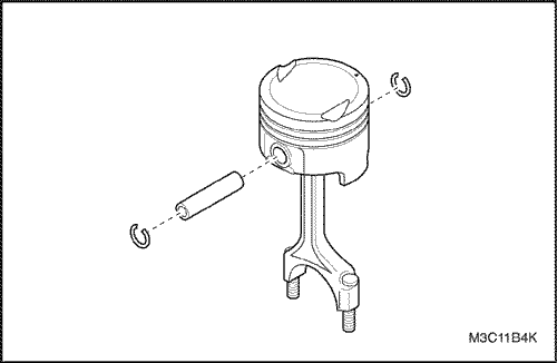
- Align the notch on
the piston and connecting rod so that the proper sides will be
facing the front of the engine.
- Install the pistion pin
guide through the piston and the connecting rod.
- Coat
the piston pin with clean oil.
- Install the piston pin
into the opposite side of the pistion.
- Install the
pistion pin into the pistion and connecting rod
assembly.
- Select a
set of new pistion rings.
- Measure the piston ring gap
using a feeler gauge.
- Increase the piston ring gap by
carefully filling off excess material if the piston ring gap is
below specifications.
- Measure the
pistion ring side clearance using a feeler gauge. Refer to "Engine Specifications" in
this section.
- If the pistion ring is too thick, try
another pistion ring.
- If no piston ring can be found
that fits to specifications the pistion ring may be ground to
size with emery paper placed on a sheet of
glass.
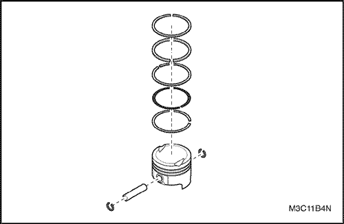
- Install a
piston oil ring, the expander and the second piston oil ring to
the bottom ring groove of the pistion.
- Install the
second compression ring to the middle ring groove of the
piston.
- Install the top compression ring to the top ring
groove of the pistion.
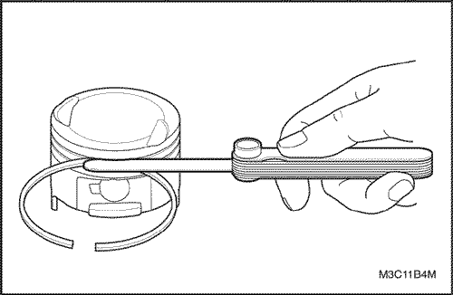
- Use a
piston ring expander to install the piston rings. Do not expand
the piston rings beyond the expansion necessary for
installation.
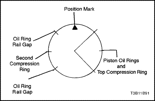
- Stagger the piston oil rings, the oil ring
rail gaps, the second compression ring, and the top compression
ring in relation to the notch on the top of the
pistion.
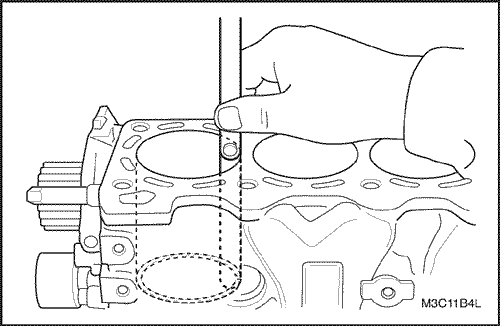
- Lubricate
the cylinder wall and the pistion rings with clean engine
oil.
- Install the piston using a ring compressor and a
wood handle. Guide the lower connecting rod end to prevent
damaging the crankshaft journal.
- Install the connecting
rod cap and the bearing. Refer to "Crankshaft Bearings and Connecting Rod Bearings - Gauging Plastic"in
this section.
- Install the
connecting rod bearing cap nuts.
Tighten
Tighten the connecting rod bearing
cap nuts to 33 N•m (24 lb-ft).
- Install the
oil pump/pickup tube.
- Install the oil pump pickup tube
bolts.
Tighten
Tighten the oil
pump pickup tube bolts to 10 N•m (89
lb-in).
- Install the
oil pan.
- Install the oil pan bolts and
nuts.
Tighten
Tighten the oil pan
bolts and nuts to 10 N•m (89
lb-in).
- Install the
lower engine mount bracket and the generator with the
bolts
Tighten
Tighten the lower
engine mount bracket bolts to 38 N•m (28
lb-ft).
- Install the upper engine mount
bracket and the generator shackle with the
bolts.
Tighten
Tighten the upper
engine mount bracket and generator shackle bolts to 38 N•m
(28 lb-ft).
- Install the
generator with the bolts and the nut.
- Install the
generator belt.
Tighten
Tighten the generator lower bolts
and the nut to 23 N•m (17 lb-ft).
Tighten the generator belt tension adjusting
bolt to 23 N•m (17 lb-ft).
- Install the
engine mount bracket.
- Install the A/C compressor/Power
steering Pump and the bracket with the bolts.
Tighten
Tighten the engime mount bracket
bolts to 20 N•m (15 lb-ft).
Tighten the A/C compressor/Power steering Pump
bracket bolts to 38 N•m (28
lb-ft).
- Install the
power steering pump bracket with the bracket bolt/nut and
adjusting bolt.
Tighten
Tighten the adjusting bolt and the
power steering rear bracket nut to 22 N•m (16
lb-ft).
- Install the power steering/air
conditioning belt.
- Install the cylinder head with the
intake manifold, the exhaust manifold, and distributor/adaaptor
attached. Refer to "Cylinder Head and Gasket"
in this section.
- Install the timing belt and
component. Refer to "Timing Belt" in this
section.
- Install the clutch and the transaxle to the
engine then engine assembly to the engine compartment. Refer to
" Engine Assembly" in
this section.
- Refill the engine coolant system.
Refer to Section 1D, Engine
Cooling.
- Bleed the power steering system
as necessary. Refer to Section 6A, Power
Steering System.
- Refill the A/C
refrigerant system as necessary. Refer to Section 7B, Manual
Control Hearing, Ventilation, and Air Conditioning
System.
- Refill the transaxle oil as
necessary.
- Connect the negative battery
cable.
- Start the engine and operate all
systems.
- Operate the idle air contril valve reset
procedure as necessary.
 | |  | |
| © Copyright
Chevrolet Europe. All rights
reserved |


