MAINTENANCE AND
REPAIR
ON-VEHICLE
SERVICE


Cylinder Head Cover
Removal
Procedure
- Disconnect the
negative battery cable.
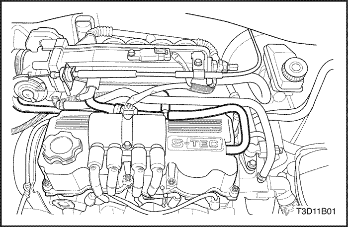
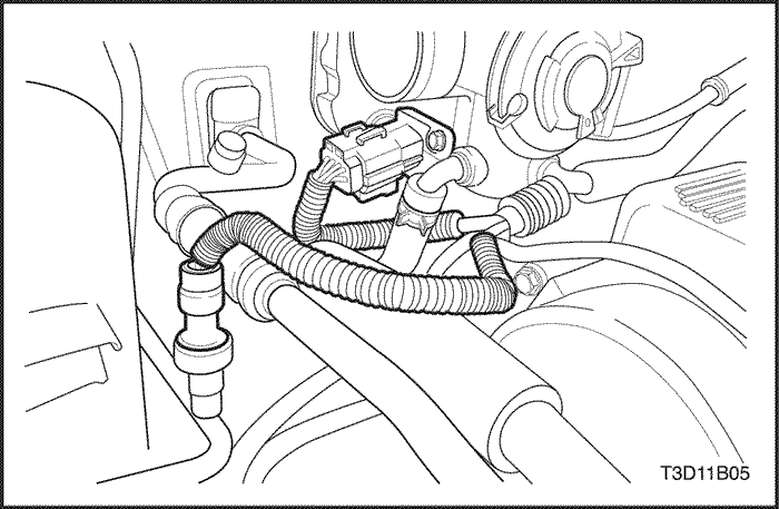
- Disconnect the PCV hose from the
cylinder head cover.
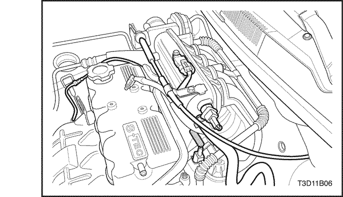
- Disconnect the ignition wires at
the spark plug and the ignition coil.
- Remove the
ignition coil. Refer to Section 1F1, Engine
Controls.
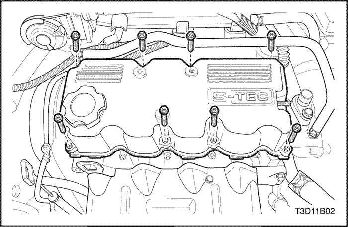
- Remove the
cylinder head cover hexagon bolts.
- Remove the cylinder
head cover with gasket.
- Clean the sealing surfaces of
the cylinder head cover and the cylinder
head.
Installation
Procedure
- Install the
cylinder head cover with the new gasket.
- Install the
bolts to the cylinder head cover.
Tighten
Tighten the cylinder head cover
hexagon bolts to 10.5 N•m (93
lb-in).
- Connect the
PCV hose to the cylinder head cover.
- Install the
ignition coil. Refer to Section 1F1, Engine
Controls.
- Connect the negative battery
cable.
Cylinder Head and Gasket
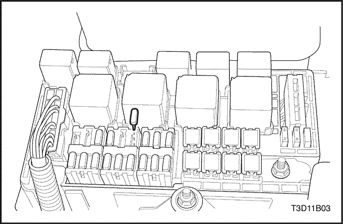
- Remove the fuel pump
fuse.
- Start the engine. After it stalls, crank the
engine for 10 seconds to rid the fuel system of fuel
pressure.
- Disconnect the negative battery
cable.
- Drain the
engine coolant. Refer to Section 1D, Engine
Cooling.
- Disconnect the PCV hose from
the cylinder head cover.
- Remove the ignition coil. Refer
to Section
1F1, Engine Controls.
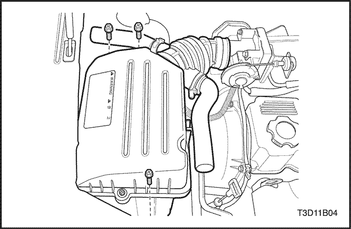
- Remove the
air cleaner housing bolts.
- Remove the air cleaner
housing.
- Disconnect
the main throttle idle actuator (MTIA)
connector.
- Disconnect the A/C pressure transducer
connector.
- Disconnect
the intake air temperature (IAT) sensor
connector.
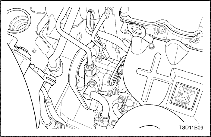
- Disconnect the throttle cable from the
throttle body.
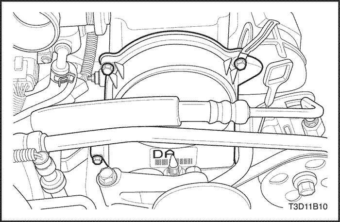
- Disconnect the brake booster vacuum hose
at the intake manifold.
- Disconnect
the fuel injector harness connectors.
- Disconnect the
fuel line at the fuel rail.
- Disconnect the fuel rail
with the fuel injector attached.
- Disconnect
the camshaft position sensor connector.
- Disconnect the
engine coolant temperature (ECT) sensor
connector.
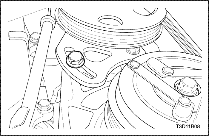
- Slightly
loosen the power steering lower adjusting bolt.
- Slightly
loosen the power steering upper adjusting bolt.
- Remove
the A/C with power steering drive belt.
- Remove the
upper timing belt cover bolts.
- Remove the upper timing
belt cover.
- Align the
camshaft gear timing mark to the notch in the rear timing belt
cover.
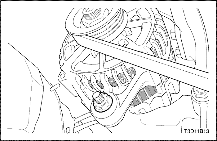
- Slightly
loosen the alternator retaining bolts.
- Remove the
alternator drive belt.
- Remove the
engine under cover.
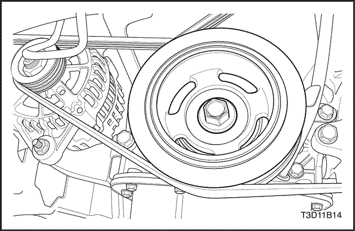
- Remove the crankshaft pulley
bolt.
- Remove the crankshaft pulley.
- Remove the
lower timing belt cover bolts.
- Remove the lower timing
belt cover.
- Remove the
timing belt automatic tensioner bolt.
- Remove the timing
belt automatic tensioner.
- Remove the timing belt. Refer
to "Timing Belt" in this
section.
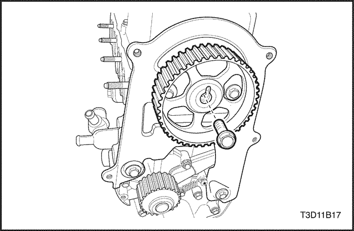
- Remove the
camshaft gear bolt from the camshaft.
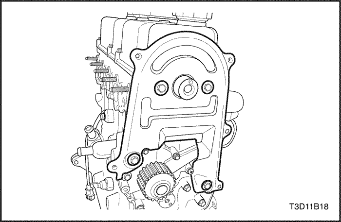
- Remove the
timing belt rear cover bolts.
- Remove the timing belt
rear cover from the cylinder head and cylinder
block.
- Remove the
heat shield mounting bolts.
- Remove the heat
shield.

- Remove the
retaining nuts from the catalytic converter at the exhaust
manifold flange.
- Remove the
cylinder head cover with the hexagon bolts.
- Remove the
cylinder head cover gasket.
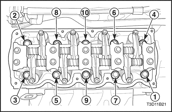
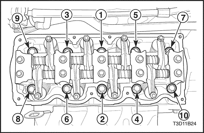
- Gradually
loosen all of the cylinder head bolts in the sequence
shown.
- Remove the cylinder head bolts.
- Remove
the cylinder head assembly from the engine block, with the
intake/exhaust manifold, throttle body, water outlet case and
cylinder head gasket.
Cleaning
Procedure
- Clean the gasket
surfaces of the cylinder head and the engine block.
- Make
sure the gasket surfaces of the cylinder head and the engine
block are free of nicks and heavy scratches.
- Clean the
cylinder head bolts.
- Inspect the cylinder head for
warpage. Refer to "Cylinder Head and Valve Train Components"
in this section.
Installation
Procedure
- Install the
cylinder head gasket.
- Install the cylinder head with the
intake manifold and the exhaust manifold
attached.
- Install the cylinder head bolts in the
sequence shown.
Tighten
Tighten the cylinder head bolts to
65-70 N•m (48–52 lb-ft).
- Install the
cylinder head cover hexagon bolts.
Tighten
Tighten the cylinder head cover
hexagon bolts to 9–12 N•m ( 80–106
lb-in).
- Install the catalytic converter
nuts at the exhaust manifold flange.
Tighten
Tighten the catalytic converter to
exhaust manifold nuts to 25–35 N•m ( 18-25
lb-ft).
- Install the
heat shield.
- Install the heat shield mounting
bolts.
Tighten
Tighten the heat
shield mounting bolts to 8-12 N•m (71-106
lb-in).
- Install the
timing belt rear cover to the cylinder head and cylinder
block.
- Install the timing belt rear cover
bolts.
Tighten
Tighten the timing
belt rear cover bolts to 9-12 N•m (80-106
lb-in).
- Install the
timing belt. Refer to "Timing Belt" in this
section.
- Install the lower timing belt
cover.
- Install the lower timing belt cover
bolts.
Tighten
Tighten the lower
timing belt cover bolts to 9-12 N•m (80-106
lb-in).
- Install the
upper timing belt cover.
- Install the upper timing belt
cover bolts.
Tighten
Tighten the upper timing belt cover
bolts to 9-12 N•m (80-106
lb-in).
- Install the
crankshaft pulley.
- Install the crankshaft pulley
bolts.
Tighten
Tighten the
crankshaft pulley bolts to 85 N•m ( 62.7
lb-ft)
- Install the
A/C with power steering drive belt. Refer to Section
6B, Accessory Belt.
- Install the
alternator drive belt.
- Connect the
engine coolant temperature (ECT) sensor
connector.
- Connect the camshaft position sensor
connector.
- Connect the
fuel line at the fuel rail.
- Connect the fuel injector
harness connectors.
- Connect the
brake booster vacuum hose at the intake
manifold.
- Connect the throttle cable to the throttle
body.
- Connect the intake air temperature (IAT) sensor
connector.
- Connect the
A/C Pressure transducer connector.
- Connect the main
throttle idle actuator (MTIA) connector.
- Install the
air cleaner housing.
- Install the air cleaner housing
bolts.
Tighten
Tighten the air
cleaner housing bolts to 7-9 N•m ( 62–80
lb-in).
- Connect the
PCV hose from the cylinder head cover.
- Install the
ignition coil. Refer to Section 1F1, Engine
Controls.
- Connect the negative battery
cable.
- Install the fuel pump fuse.
- Refill the
engine cooling system. Refer to Section 1D, Engine
Cooling.
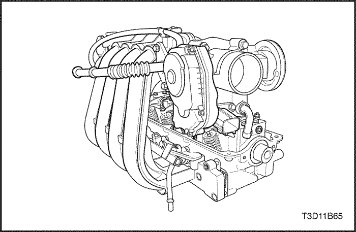
Camshaft
Removal
Procedure
- Remove the timing
belt. Refer to "Timing Belt" in
thissection.
- Remove the ignition coil at the cylinder
head cover.
- Drain the
engine coolant. Refer to Section 1D, Engine
Cooling.
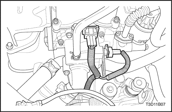
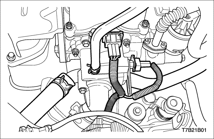
- Disconnect the camshaft
position (CMP) sensor connector.
- Disconnect the engine
coolant temperature (ECT) sensor connector.
- Disconnect
the radiator upper hose at the water outlet
case.
- Disconnect the throttle body and heater feeding
hoses.
- Remove the
cylinder head cover with gasket.
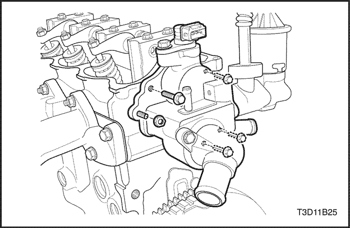
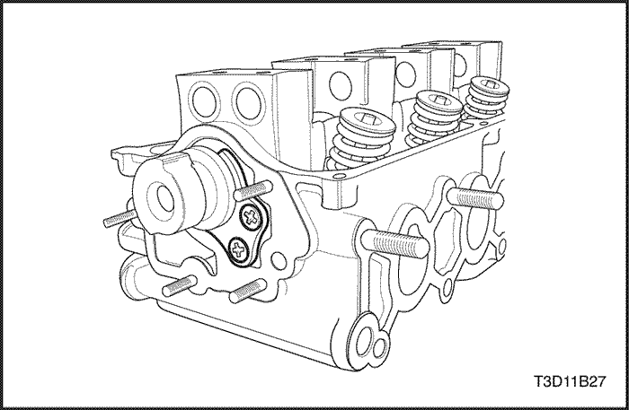
- Remove the
water outlet case nuts and the bolt.
- Remove the water
outlet case at the cylinder head.
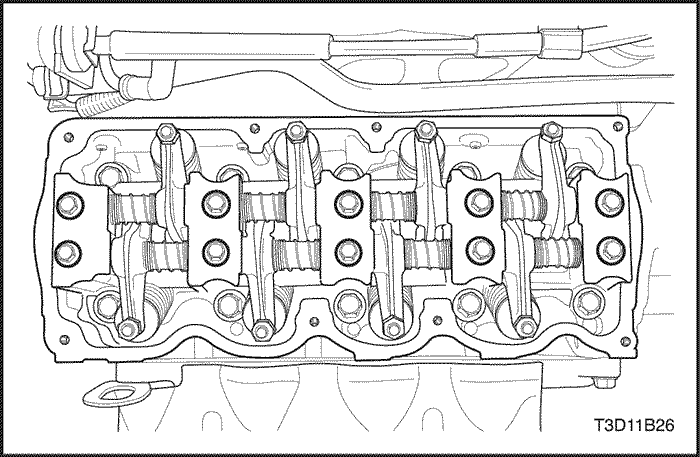
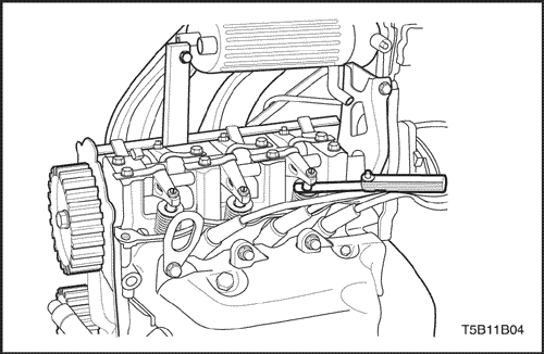
- Remove the
rocker arm shaft mounting bolts.
- Remove the rocker arm
spring and the rocker arm.
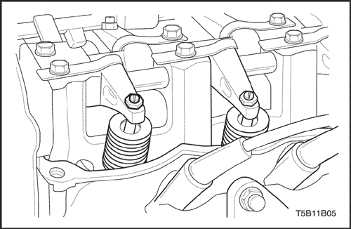
- Remove the
screws with the camshaft thrust plate.
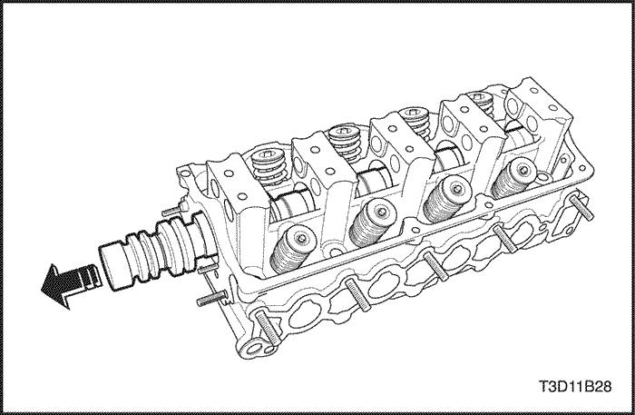
- Remove the
camshaft.
Installation
Procedure
- Install the
camshaft.
- Install the camshaft thrust
plate.
- Install the camshaft thrust plate
screws.
Tighten
Tighten the
camshaft thrust plate screws to 10 N•m ( 89
lb-in).
- Install the
rocker arm spring and the rocker arm.
- Install the rocker
arm shaft.
- Install the rocker arm shaft mounting
bolts.
Tighten
Tighten the rocker
arm shaft mounting bolts to 10 N•m ( 89
lb-in).
- Install the
water outlet case at the cylinder head.
- Install the
water outlet case nuts and the bolt.
Tighten
Tighten the water outlet case nuts
and the bolt to 10.5 N•m (93
lb-in).
- Install the
cylinder head cover gasket.
- Install the cylinder head
cover.
- Install the cylinder head cover hexagon
bolts.
Tighten
Tighten the
cylinder head cover hexagon bolts to 10.5 N•m (93
lb-in).
- Connect the
throttle body and heater feeding hose.
- Connect the
radiator upper hose.
- Connect the CMP and ECT sensor
connectors.
- Install the
ignition coil. Refer to Section 1F1, Engine
Controls.
- Connect the PCV hose to the
cylinder head cover.
- Refill the engine cooling system.
Refer to Section 1D, Engine
Cooling.
- Connect the negative battery
cable.
- Install the timing belt. Refer to "Timing Belt" in
thissection.
Adjustment of Valve
Clearance
Removal
Procedure
- Remove the cylinder
head cover hexagon bolts and remove the cover.
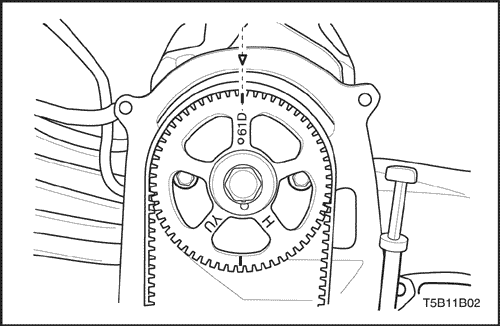
- Turn over
the crankshaft to make NO.1 cylinder matched with the
compression top dead center. When the camshaft sprocket notch is
aligned with the timing belt rear cover triangle pointer and the
crankshaft sprocket point is aligned with the oil pump housing
point, the compression top dead center is on the ignition
sequence for NO.1 cylinder.
- Check the
valve clearance for NO.1 cylinder compression top dead
center.
- If the checking for the valve clearance of No1
cylinder compression top dead center is over, position No.1
cylinder on the exhaust top dead center as rotating the
crankshaft in a 360–degree arc. When the camshaft sprocket point
is aligned with the timing belt rear cover triangle pointer, the
exhaust top dead center is on the ignition sequence for No.1
cylinder.
- Check the
valve clearance for the No.1 cylinder exhaust top dead
center.
Condition | Cylinder No. | 1 | 2 | 3 | 4 |
Exhaust top dead center
of No.1 cylinder | Intake | . | . | O | O |
Exhaust | . | O | . | O |
* O marks indicates the place where the
valve clearance can be checked and adjusted.
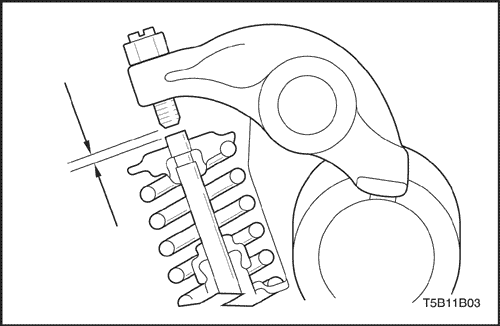
- Check the
adjust the valve clearance using thickness gauge. The measured
value of valve clearance should meet the specified value. If
not, adjust the valve clearance.
Important : In case of hot engine, warm up
the engine until the electric cooling fan begins to work
and stop engine to adjust the clearance with 20-30
minutes there from.
- Unit
: mm (in.)
Item | Specified
value |
Valve Clearance | Cold | Intake | 0.15±0.02
(0.0059±0.0008) |
. | Exhaust | 0.2±0.02
(0.00787±0.0008) |
Hot | Intake | 0.25±0.02
(0.0098±0.0008) |
. | Exhaust | 0.3±0.02
(0.0118±0.0008) |
- When
adjusting the valve clearance, loosen the adjust nut and then
tighten or loosen the adjust rod properly.
Valve Timing Check and
Adjustment
- After removing
the air cleaner housing, loosen the bolts and remove the timing
belt front upper cover.
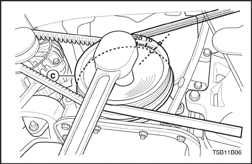
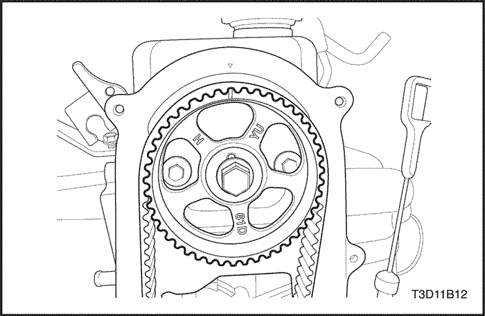
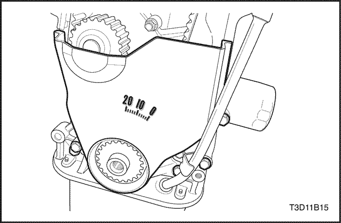
- Turning the
crankshaft clockwise twice, align the notch on the crankshaft
pulley with the mark 0 for the timing check on the timing belt
front lower cover.
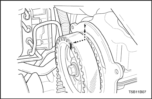
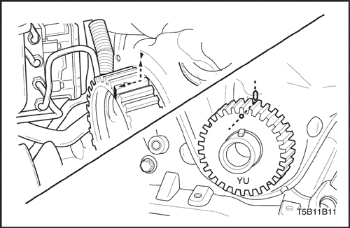
- Check if
the notch on the camshaft sprocket is aligned with the triangle
pointer on the timing belt rear cover.
Important : Notch should be aligned with
pointer to set the valve timing
normally.
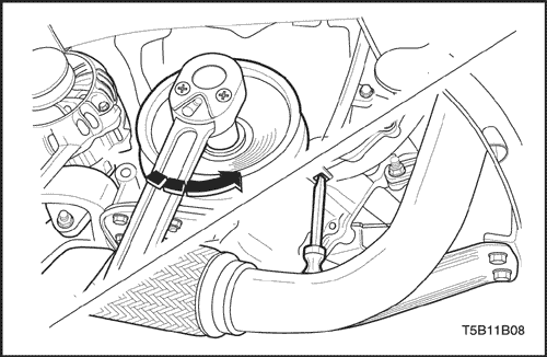
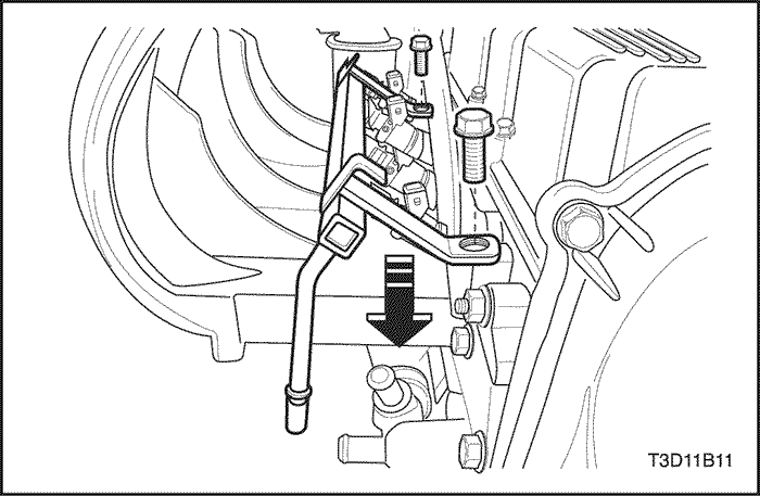
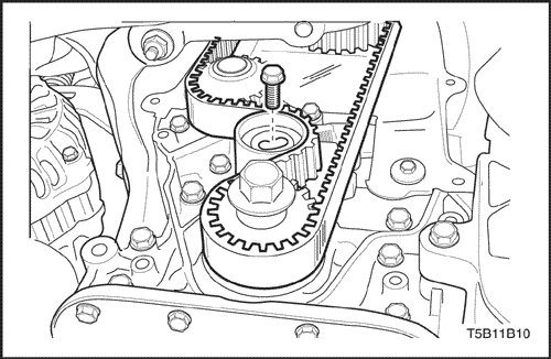
- Loosen the
bolt and remove the timing belt pulley. In loosening the bolt,
use the driver in the picture shown.
- Remove the
oil level gauge guide tube and the timing belt front lower
cover.
- Remove the
timing belt tensioner and the timing belt.
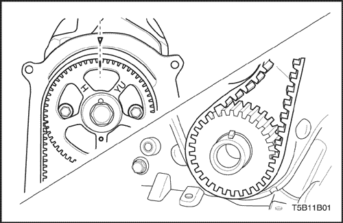
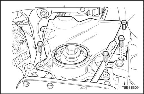
- Using the
bolt, turn the crankshaft clockwise to align the mark on the
crankshaft sprocket with the pointer on the oil pump housing.
Then, turn the camshaft to align the notch with the
pointer.
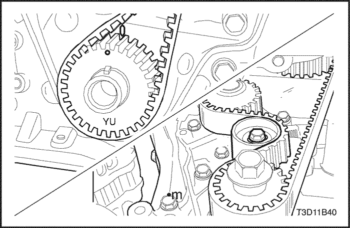
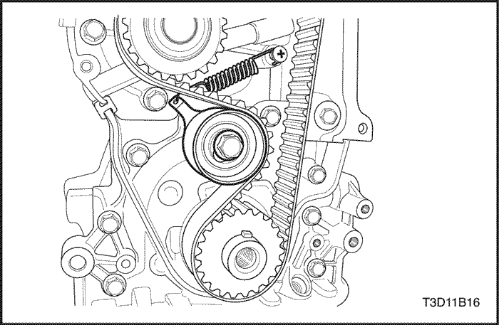
- Install the
timing belt and the tensioner.
- Turning the crankshaft
clockwise twice, align the mark with the pointer and tighten the
tensioner bolt.
Tighten
Tighten the tensioner bolt to 19 N•m
(14 lb-ft).
Timing Belt
- Disconnect the negative battery
cable.
- Disconnect the air cleaner outlet hose from the
throttle body.
- Remove the air cleaner housing
bolts.
- Remove the air cleaner housing.
- Remove
the right front wheel. Refer to Section 2E,Tires and
Wheels.
- Remove the right front wheel
well splash shield.
- Remove the
A/C compressor drive belt.
- Remove the alternator drive
belt.
- Remove the upper timing belt cover
bolts.
- Remove the upper timing belt
cover.
- Align the
mark on the camshaft gear with the notch on the rear timing belt
cover by turning the crankshaft pulley.
- Remove the
crankshaft pulley bolt.
- Remove the crankshaft
pulley.
- Remove the lower timing belt cover
bolts.
- Remove the lower timing belt
cover.
- Loosen the
timing belt tensioner bolt.
- Remove the timing
belt.
Installation
Procedure
Important : If the camshaft or crankshaft
rotates in the process of installing the timing belt,
Perform the valve timing setting necessary. Refer to "Valve Timing Check and Adjustment"in
this section. - Install the
timing belt tensioner bolt.
Tighten
Tighten the timing belt tinsioner
bolt to 19 N•m ( 14 lb-ft).
Important : Turn the crankshaft twice to
align the notch on the camshaft with the pointer on the
rear cover and tighten the tensioner
bolt.
- Install the lower
timing belt cover.
Tighten
Tighten the lower timing belt cover
bolts to 10.5 N•m ( 93 lb-in).
- Install
the oil level gauge guide tube bolt.
Tighten
Tighten the oil level gauge guide
tube bolt to 10.5 N•m (93
lb-in).
- Install the
upper timing belt cover.
Tighten
Tighten the upper timing belt cover
bolts to 10.5 N•m ( 93 lb-in).
- Install
the crankshaft pulley bolt.
Tighten
Tighten the crankshaft pulley bolts
to 70 N•m (52 lb-ft).
- Install the
alternator drive belt.
- Install the A/C compressor drive
belt.
- Install the right front wheel. Refer to Section
2E,Tires and Wheels.
- Install the air
cleaner housing.
- Install the air cleaner housing
bolts.
Tighten
Tighten the air
cleaner housing bolts to 12 N•m (106
lb-in).
 | |  | |
| © Copyright
Chevrolet Europe. All rights
reserved |


