Diagnostic Trouble Code (DTC) P0300
Multiple Cylinder Misfire Detected
System Description
The engine control module (ECM) uses information from the crankshaft position (CKP) sensor and the camshaft position (CMP) sensor in order to determine when an engine misfire is occurring. By monitoring variations in the crankshaft rotation speed for each cylinder, the ECM is able to detect individual misfire events. A misfire rate that is high enough can cause overheating and damage to the 3-way catalytic converter (TWC) under certain driving conditions. The malfunction indicator lamp (MIL) will flash ON and OFF when the conditions for TWC damage are present. If the ECM detects a misfire rate sufficient to cause emission levels to exceed a predetermined value, DTC P0300 sets.
Condition for Running the DTC
Conditions for Setting the DTC
- The ECM detects a crankshaft rotation speed variation indicating a misfire sufficient to cause emission levels to exceed a predetermined value.
Action Taken When the DTC Sets
- The Malfunction Indicator Lamp (MIL) will illuminate.
- The ECM will record operating conditions at the time the diagnostic fails. This information will be stored in the Freeze Frame and Records buffers.
- A history DTC is stored.
Conditions for Clearing the MIL/DTC
- The MIL will turn off at the end of a consecutive validation cycle in which the diagnostic runs without a fault.
- A history DTC will clear after 40 warm up cycles without a fault.
- DTC(s) can be cleared by using the scan tool.
Diagnostic Aids
An intermittent can also be the result of a defective reluctor wheel. Remove the CKP sensor and inspect the reluctor wheel through the sensor mount hole. Check for porosity and the condition of wheel. If the DTC is intermittent refer to
"Symptoms Diagnosis" in this section.
Test Description
Number(s) below refer to the step number(s) on the Diagnostic Table.
- The Diagnostic System Check prompts the technician to complete some basic checks and store the freeze frame and failure records data on the scan tool if applicable. This creates an electronic copy of the data taken when the malfunction occurred. The information is then stored on the scan tool for later reference.
- A visual/physical inspection should include checking the following components:
- The wiring for proper connections, pinches or cuts.
- The ECM grounds for being clean and tight.
- The vacuum hoses for splits, kinks, and proper connections. Check thoroughly for any type of leak or restriction.
- For air leaks at the throttle body mounting area and intake manifold sealing surfaces.
- When all the accumulators are relatively equal, then the misfire is being caused by something that affects the entire engine. When they are not then the misfire is being caused by something that is specific to two or more cylinders.
- Whenever the misfire is not present operating the vehicle may be necessary to duplicate the conditions in the Freeze Frame Data in order to detect misfire. Depending on the engine load, the conditions may have to be maintained for up to 20 seconds. Whenever the misfire accumulators start to increment, then misfire is present. A history misfire counter will store the number of misfires that have occurred until the DTC is cleared.
- Check fuel for water, alcohol, etc.
- A basic engine problem that affects all cylinders is the only possibility at this point. (Cam timing, throttle body leak, restricted air flow, etc.)
- Tests the ignition system voltage output using a spark tester.
- Replace any spark plugs that are worn, cracked or fouled.
- Checks for voltage at the ignition feed circuit.
- Whenever the driver circuit is shorted to ground, the light will be on steady. When the driver circuit is shorted to voltage or open, the light will be off.
- Since voltage is supplied to the fuel injector on a single circuit, the malfunction could only be a poor connection or open in the fuel injector harness. An open before the harness would result in an "Engine Cranks But Will Not Run" complaint.
DTC P0300 - Multiple Cylinder Misfire Detected
| Step | Action | Value(s) | Yes | No |
| 1 | Perform the Diagnostic System Check. Was the check performed? | - | Go to Step 2 | |
| 2 | - Install a scan tool to the Data Link Connector (DLC).
- Turn the ignition ON, with the engine OFF.
- Request Diagnostic Trouble Codes (DTCs).
Are DTCs P0261, P0262, P0264, P0265, P0267, P0268, P0270, or P0271 set? | - | Go to applicable DTC table | Go to Step 3 |
| 3 | - Perform a visual/physical inspection.
- Make any repairs that are necessary.
Is the repair complete? | - | Go to Step 27 | Go to Step 4 |
| 4 | Start the engine and allow it to idle. Are any Misfire Current counters incrementing? | - | Go to Step 5 | Go to Step 6 |
| 5 | Are all counters equal (within a percentage of each other)? | - | Go to Step 7 | Go to Step 11 |
| 6 | - Turn the ignition ON, with the engine OFF.
- Review the Freeze Frame data, and note the parameters.
- Operate the vehicle within the Freeze Frame conditions and conditions for setting this DTC as noted.
Are any Misfire Current counters incrementing? | - | Go to Step 5 | |
| 7 | - Turn the engine OFF.
- Install a fuel pressure gauge to the fuel rail.
- Observe the fuel pressure with the engine running.
Is the fuel pressure within the specified value? | 55~58 psi (380~402 kPa) | Go to Step 8 | |
| 8 | Check the fuel for contamination. Is the fuel OK? | - | Go to Step 9 | Go to Step 10 |
| 9 | Check for a basic engine problem and repair as necessary. Is the repair complete? | - | Go to Step 27 | - |
| 10 | Replace the contaminated fuel. Is the repair complete? | - | Go to Step 27 | - |
| 11 | - Turn the engine OFF.
- Disconnect the fuel injector harness connector.
- Install a spark tester on cylinder #1 spark plug cable.
- Crank the engine and check for spark.
- Repeat the above procedure on cylinders #2, #3 and #4.
Is a spark observed on all four spark plug cables? | - | Go to Step 12 | Go to Step 20 |
| 12 | Replace any malfunctioning spark plugs if necessary. Is the repair complete? | - | Go to Step 27 | Go to Step 13 |
| 13 | - Turn the engine OFF.
- Disconnect the fuel injector connectors from the injectors.
- Install an injector test light on the injector harness connector for the cylinders that had misfired.
- Crank the engine and note the test light.
Does the injector test light blink? | - | Go to Step 14 | Go to Step 15 |
| 14 | Perform the Fuel Injector Balance Test. Are the fuel injectors OK? | - | Go to Step 9 | Go to Step 16 |
| 15 | - Disconnect the injector test light.
- With a test light connected to ground, probe the ignition feed terminal 2 of the injector harness connector for each cylinder that had misfire.
- Crank the engine.
Does the test light illuminate? | - | Go to Step 17 | Go to Step 19 |
| 16 | Replace any malfunctioning fuel injectors. Is the repair complete? | - | Go to Step 27 | - |
| 17 | Check the affected fuel injector driver circuit at the corresponding terminals for an open, short, or short to voltage. Is a problem found? | - | Go to Step 18 | Go to Step 24 |
| 18 | Repair the open or the shorted fuel injector driver circuit. Is the repair complete? | - | Go to Step 27 | - |
| 19 | Repair the open ignition feed circuit between the fuel injector harness connector and the fuel injector connector. Is the repair complete? | - | Go to Step 27 | - |
| 20 | Measure the resistance of the spark plug cable that the spark plug tester did not spark. Is the resistance of the spark plug cable less than the specified value? | 30000Ω | Go to Step 21 | Go to Step 25 |
| 21 | Inspect the Engine Control Module (ECM) connector and connections. Are the connections OK? | - | Go to Step 22 | Go to Step 23 |
| 22 | Check the affected cylinders ignition control circuit for an open or short and repair as necessary. Is the repair complete? | - | Go to Step 27 | Go to Step 26 |
| 23 | Repair the connector or connections. Is the repair complete? | - | Go to Step 27 | - |
| 24 | - Turn the ignition OFF.
- Replace the ECM.
Is the repair complete? | - | Go to Step 27 | - |
| 25 | Replace the spark plug cable. Is the repair complete? | - | Go to Step 27 | - |
| 26 | Replace the faulty ignition coil. Is the repair complete? | - | Go to Step 27 | Go to Step 24 |
| 27 | - Using the scan tool, clear the DTCs.
- Start the engine and idle at normal operating temperature.
- Operate the vehicle within the conditions for setting this DTC as supported in the text.
Does the scan tool indicate that this diagnostic ran and passed? | - | Go to Step 28 | Go to Step 2 |
| 28 | Check if any additional DTCs are set. Are any DTCs displayed that have not been diagnosed? | - | Go to applicable DTC table | System OK |
Diagnostic Trouble Code (DTC) P0327
Knock Sensor Circuit Fault
Circuit Description
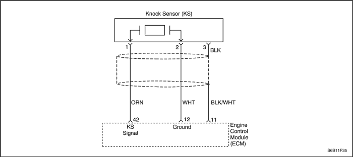
The knock sensor(KS) system is used to detect engine detonation, allowing the engine control module(ECM) to retard ignition control spark timing based on the KS signal being received. The KS produces an AC signal so that under a no knock condition the signal on the KS circuit measures about 0.007V AC. The KS signal's amplitude and frequency depend upon the amount of knock being experienced. The ECM contains a non-replaceable knock filter module called a signal-to-noise enhancement filter (SNEF) module. This filter module in the ECM determines whether knock is occurring by comparing the signal level on the KS circuit with the voltage level on the noise channel. The noise channel allows the ECM to reject any false knock signal by knowing the amount of normal engine mechanical noise present. Normal engine noise varies depending on engine speed and load. When the ECM determines that an abnormally low noise channel voltage level is being experienced, a DTC P0327 will set.
Condition for Running the DTC
- Engine coolant temperature is higher than 65°C (149°F).
- Mass air flow is greater than 170mg/TDC.
- Engine speed is higher than 2496 rpm.
Conditions for Setting the DTC
- The KS signal voltage is less than 0.3490V for 10 seconds.
Action Taken When the DTC Sets
- The Malfunction Indicator Lamp (MIL) will not illuminate.
- The ECM will record operating conditions at the time the diagnostic fails. This information will be stored in the Freeze Frame and Failure Records buffers.
- A history DTC is stored.
Conditions for Clearing the MIL/DTC
- A history DTC will clear after 40 warm-up cycles without a fault.
- DTC(s) can be cleared by using the scan tool.
Diagnostic Aids
Check and correct any abnormal engine noise before using the diagnostic table.
Any circuitry that is suspected as causing engine noise complaint should be thoroughly checked for the following conditions :
- Backed-out terminals
- Improper mating
- Broken locks
- Improperly formed
- Damaged terminals
- Poor terminal-to-wire connection
- Physical damage to the wiring harness
DTC P0327 - Knock Sensor Circuit Fault
| Step | Action | Value(s) | Yes | No |
| 1 | Perform the Diagnostic System Check. Is the system check complete? | - | Go to Step 2 | |
| 2 | - Start the engine.
- Install a scan tool.
- Clear the Diagnostic Trouble Codes (DTCs).
- Operate the vehicle within the Freeze Frame conditions and Conditions for Running the DTC as noted.
Does the Malfunction Indicator (MIL) illuminate? | - | Go to Step 4 | Go to Step 3 |
| 3 | - Turn the ignition switch ON, with the engine OFF.
- Review the Freeze Frame data and note the parameters.
- Operate the vehicle within the Freeze Frame conditions and Conditions for Running the DTC as noted.
Does the Malfunction Indicator (MIL) illuminate? | - | Go to Step 4 | Go to Step 12 |
| 4 | Listen to the engine while raising and lowering the engine speed. Is a knock or audible noise present? | - | Go to Step 5 | Go to Step 6 |
| 5 | Repair the mechanical engine problem or a loose bracket or component. Is the repair complete? | - | Go to Step 12 | - |
| 6 | - Turn the ignition switch to lock.
- Disconnect the engine control module(ECM).
- With a digital voltmeter (DVM) connected to ground, measure the resistance of the knock sensor through the knock sensor signal circuit, terminal 42.
Is the measured value within the specified value? | 90-100KΩ | Go to Step 7 | Go to Step 9 |
| 7 | Check for a poor connection at the ECM connector, knock sensor (KS) signal circuit and repair as necessary. Is a repair necessary? | - | Go to Step 12 | Go to Step 8 |
| 8 | Replace the engine control module(ECM). Is the replacement complete? | - | Go to Step 12 | Go to Step 10 |
| 9 | Check the KS electrical connector for a poor connection and repair an necessary. Is a repair necessary? | - | Go to Step 12 | Go to Step 10 |
| 10 | Check the KS signal circuit for an open or a low voltage or voltage and repair as necessary. Is a repair necessary? | - | Go to Step 12 | Go to Step 11 |
| 11 | Replace the KS. Is the replacement complete? | - | Go to Step 12 | - |
| 12 | - Using the scan tool, clear the DTCs.
- Start the engine and idle at normal operating temperature.
- Operate the vehicle within the conditions for running this DTC as specified in the supporting text.
Does the scan tool indicate that this diagnostic has run and passed? | - | Go to Step 13 | Go to Step 2 |
| 13 | Check if any additional DTCs are set. Are any DTCs displayed that have not been diagnosed? | - | Go to applicable DTC table | System OK |
Diagnostic Trouble Code (DTC) P0335
Crankshaft Position Sensor Electrical Error
Circuit Description
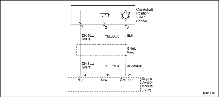
The 58X reference signal is produced by the crankshaft position (CKP) sensor. During one crankshaft revolution, 58 crankshaft pulses will be produced. The engine control module(ECM) uses the 58X reference signal to calculate engine rpm and CKP. The ECM constantly monitors the number of pulses on the 58X reference circuit and compares them to the number of camshaft position (CMP) signal pulses being received.
Condition for Running the DTC
Conditions for Setting the DTC
- The minimum of the CKP sensor signal voltage is less than 1.3196V.
Or
- The maximum of the CKP sensor signal voltage is higher than 2.3998V.
Or
- The difference between the minimum and maximum of the CKP sensor signal voltage is higher than 0.3617V.
Action Taken When the DTC Sets
- The Malfunction Indicator Lamp (MIL) will illuminate.
- The ECM will record operating conditions at the time the diagnostic fails. The information will be stored in the Freeze Frame and Failure Records buffers.
- A history DTC is stored.
Conditions for Clearing the MIL/DTC
- The MIL will turn off at the end of three consecutive validation cycles in which the diagnostic runs without a fault.
- A history DTC will clear after 40 warm-up cycles without a fault.
- DTC(s) can be cleared by using the scan tool.
Diagnostic Aids
An intermittent may be caused by a poor connection, rubbed-through wire insulation or a wire broken inside the insulation. Check for :
Poor connection - inspect the ECM harness and connectors for improper mating, broken locks, improperly formed or damaged terminals, and poor terminal-to-wire connection.
Damaged harness - inspect the wiring harness for damage. If the harness appears to be OK, disconnect the ECM, turn the ignition ON and observe a voltmeter connected to the 58X reference circuit at the ECM harness connector while moving the connectors and the wiring harness related to the ECM. A change in voltage will indicate the location of the fault.
Review the failure records vehicle mileage since the diagnostic test failed may help determine how often the condition that caused the DTC to be set occurs. This may assist in diagnosing the condition.
DTC P0335 - Crankshaft Position Sensor Electrical Error
| Step | Action | Value(s) | Yes | No |
| 1 | Perform the Diagnostic System Check. Is the system check complete? | - | Go to Step 2 | |
| 2 | Attempt to start the engine. Does the engine start? | - | Go to Step 3 | |
| 3 | - Review and record Failure Records information.
- Clear the DTC P0335.
- Start the engine and idle for 1 minute.
- Observe the diagnostic trouble codes (DTCs).
Does the DTC P0335 reset? | - | Go to Step 4 | |
| 4 | - Disconnect the engine control module(ECM) and the crankshaft position (CKP) sensor.
- Check for an open or short to ground in the CKP sensor connector and the ECM harness connector.
Is the problem found? | - | Go to Step 5 | Go to Step 6 |
| 5 | Repair the open or short to ground in the 58X reference circuit between the CKP sensor connector and the ECM harness connector. Is the repair complete? | - | Go to Step 11 | - |
| 6 | - Reconnect the ECM and CKP sensor.
- Connect a digital voltmeter (DVM) to measure voltage on the 58X reference circuit, terminal 54 at the ECM connector.
- Observe the voltage while cranking the engine.
Is the voltage near the specified value? | 2.5V | Go to Step 9 | Go to Step 7 |
| 7 | Check the connection at the CKP sensor and replace the terminals if necessary. Do any terminals require replacement? | - | Go to Step 11 | Go to Step 8 |
| 8 | Replace the CKP sensor. Is the replacement complete? | - | Go to Step 11 | - |
| 9 | Check the connections at the ECM and replace the terminals if necessary. Do any terminal require replacement? | - | Go to Step 11 | Go to Step 10 |
| 10 | Replace the ECM. Is the replacement complete? | - | Go to Step 11 | - |
| 11 | - Using the scan tool, clear the DTCs.
- Start the engine and idle at normal operating temperature.
- Operate the vehicle within the conditions for setting this DTC as specified in the supporting text.
Does the scan tool indicate that this diagnostic run and passed? | - | Go to Step 12 | Go to Step 2 |
| 12 | Check if any additional DTCs are set. Are any DTCs displaced that have not been diagnosed? | - | Go to applicable DTC table | System OK |
 | |  | |
| © Copyright Chevrolet Europe. All rights reserved |