Diagnostic Trouble Code (DTC) P0336
Crankshaft Position Sensor Pulse Error
Circuit Description
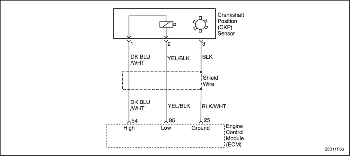
The 58X reference signal is produced by the crankshaft position (CKP) sensor. During one crankshaft revolution, 58 crankshaft pulses will be produced. The engine control module(ECM) uses the 58X reference signal to calculate engine rpm and CKP. The ECM constantly monitors the number of pulses on the 58X reference circuit and compares them to the number of camshaft position (CMP) signal pulses being received.
Conditions for Running the DTC
- Engine is running.
- Number of extra or missing teeth per revolution is 2 or more.
Conditions for Setting the DTC
- Extra or missing pulses detected between consecutive 58X reference pulses.
Action Taken When the DTC Sets
- The Malfunction Indicator Lamp (MIL) will illuminate.
- The ECM will record operating conditions at the time the diagnostic fails. The information will be stored in the Freeze Frame and Failure Records buffers.
- A history DTC is stored.
Conditions for Clearing the MIL/DTC
- The MIL will turn off at the end of three consecutive validation cycles in which the diagnostic runs without a fault.
- A history DTC will clear after 40 warm-up cycles without a fault.
- DTC(s) can be cleared by using the scan tool.
Diagnostic Aids
An intermittent may be caused by a poor connection, rubbed-through wire insulation or a wire broken inside the insulation. Check for :
Poor connection - inspect the ECM harness and connectors for improper mating, broken locks, improperly formed or damaged terminals, and poor terminal-to-wire connection.
Damaged harness - inspect the wiring harness for damage. If the harness appears to be OK, disconnect the ECM, turn the ignition ON and observe a voltmeter connected to the 58X reference circuit at the ECM harness connector while moving the connectors and the wiring harness related to the ECM. A change in voltage will indicate the location of the fault.
Review the failure records vehicle mileage since the diagnostic test failed may help determine how often the condition that caused the DTC to be set occurs. This may assist in diagnosing the condition.
DTC P0336 - Crankshaft Position Sensor Pulse Error
| Step | Action | Value(s) | Yes | No |
| 1 | Perform the Diagnostic System Check. Is the system check complete? | - | Go to Step 2 | |
| 2 | Attempt to start the engine. Does the engine start? | - | Go to Step 3 | |
| 3 | - Review and record Failure Records information.
- Clear the DTC P0336.
- Start the engine and idle for 1 minute.
- Observe the diagnostic trouble codes (DTCs).
Does the DTC P0336 reset? | - | Go to Step 4 | |
| 4 | - Disconnect the engine control module(ECM) and the crankshaft position (CKP) sensor.
- Check for an open or a low voltage in the CKP sensor connector and the ECM harness connector.
Is the problem found? | - | Go to Step 5 | Go to Step 6 |
| 5 | Repair the open or low voltage in the 58X reference circuit between the CKP sensor connector and the ECM harness connector. Is the repair complete? | - | Go to Step 11 | - |
| 6 | - Reconnect the ECM and CKP sensor.
- Connect a digital voltmeter (DVM) to measure voltage on the 58X reference circuit, terminal 54 at the ECM connector.
- Observe the voltage while cranking the engine.
Is the voltage near the specified value? | 2.5V | Go to Step 9 | Go to Step 7 |
| 7 | Check the connection at the CKP sensor and replace the terminals if necessary. Do any terminals require replacement? | - | Go to Step 11 | Go to Step 8 |
| 8 | Replace the CKP sensor. Is the replacement complete? | - | Go to Step 11 | - |
| 9 | Check the connections at the ECM and replace the terminals if necessary. Do any terminal require replacement? | - | Go to Step 11 | Go to Step 10 |
| 10 | Replace the ECM. Is the replacement complete? | - | Go to Step 11 | - |
| 11 | - Using the scan tool, clear the DTCs.
- Start the engine and idle at normal operating temperature.
- Operate the vehicle within the conditions for setting this DTC as specified in the supporting text.
Does the scan tool indicate that this diagnostic run and passed? | - | Go to Step 12 | Go to Step 2 |
| 12 | Check if any additional DTCs are set. Are any DTCs displaced that have not been diagnosed? | - | Go to applicable DTC table | System OK |
Diagnostic Trouble Code (DTC) P0337
Crankshaft Position Sensor No Signal
Circuit Description
The 58X reference signal is produced by the crankshaft position (CKP) sensor. During one crankshaft revolution, 58 crankshaft pulses will be produced. The engine control module(ECM) uses the 58X reference signal to calculate engine rpm and CKP. The ECM constantly monitors the number of pulses on the 58X reference circuit and compares them to the number of camshaft position (CMP) signal pulses being received.
Conditions for Running the DTC
- Engine is running.
- No fault in the CMP sensor exist.
Conditions for Setting the DTC
- No crankshaft teeth detected.
Action Taken When the DTC Sets
- The Malfunction Indicator Lamp (MIL) will illuminate.
- The ECM will record operating conditions at the time the diagnostic fails. The information will be stored in the Freeze Frame and Failure Records buffers.
- A history DTC is stored.
Conditions for Clearing the MIL/DTC
- The MIL will turn off at the end of three consecutive validation cycles in which the diagnostic runs without a fault.
- A history DTC will clear after 40 warm-up cycles without a fault.
- DTC(s) can be cleared by using the scan tool.
Diagnostic Aids
An intermittent may be caused by a poor connection, rubbed-through wire insulation or a wire broken inside the insulation. Check for :
Poor connection - inspect the ECM harness and connectors for improper mating, broken locks, improperly formed or damaged terminals, and poor terminal-to-wire connection.
Damaged harness - inspect the wiring harness for damage. If the harness appears to be OK, disconnect the ECM, turn the ignition ON and observe a voltmeter connected to the 58X reference circuit at the ECM harness connector while moving the connectors and the wiring harness related to the ECM. A change in voltage will indicate the location of the fault.
Review the failure records vehicle mileage since the diagnostic test failed may help determine how often the condition that caused the DTC to be set occurs. This may assist in diagnosing the condition.
DTC P0337 - Crankshaft Position Sensor No Signal
| Step | Action | Value(s) | Yes | No |
| 1 | Perform the Diagnostic System Check. Was the check performed? | - | Go to Step 2 | |
| 2 | - Turn the ignition OFF.
- Install a scan tool to the Data Link Connector (DLC).
- Start the engine.
- Operate the vehicle within the Freeze Frame conditions and Conditions for Running the DTC as noted.
Does Diagnostic Trouble Code (DTC) P0337 set? | - | Go to Step 3 | Go to Step 10 |
| 3 | - Turn the ignition OFF.
- Disconnect the Crankshaft Position (CKP) sensor connector.
- Turn the ignition ON.
- Using a voltmeter, check the voltage between the CKP sensor wiring harness connector (Engine Control Module [ECM] side) terminal 1 and ground.
Does the voltage within the value specified? | 1.4 volts | Go to Step 4 | Go to Step 5 |
| 4 | Using a voltmeter, check the voltage between the CKP sensor wiring harness connector (ECM side) terminal 2 and ground. Does the voltage within the value specified? | 1.4 volts | Go to Step 6 | Go to Step 5 |
| 5 | - Turn the ignition OFF.
- Disconnect the ECM connector.
- Turn the ignition ON.
- Using a voltmeter, check the out put voltage of the ECM terminal 54 and 85.
Does the voltage within the value specified? | 11-14 volts | Go to Step 8 | Go to Step 9 |
| 6 | - Reconnect the CKP sensor.
- Using a voltmeter, back probe the ECM connector terminal 54 and 85.
- Observe the voltage while cranking the engine.
Does the voltage fluctuate between the specified value? | 1.3-1.6 volts | | Go to Step 7 |
| 7 | - Turn the ignition OFF.
- Replace the CKP sensor.
Is the repair complete? | - | Go to Step 10 | - |
| 8 | Check the CKP sensor high and low circuits for an open, short to ground or voltage and repair as needed. Is the repair complete? | - | Go to Step 10 | - |
| 9 | - Turn the ignition OFF.
- Replace the ECM.
Is the repair complete? | - | Go to Step 10 | - |
| 10 | - Using the scan tool, clear the DTCs.
- Start the engine and idle at normal operating temperature.
- Operate the vehicle within the conditions for setting this DTC as supported in the text.
Does the scan tool indicate that this diagnostic ran and passed? | - | Go to Step 11 | Go to Step 2 |
| 11 | Check if any additional DTCs are set. Are any DTCs displayed that have not been diagnosed? | - | Go to applicable DTC table | System OK |
Diagnostic Trouble Code (DTC) P0341
Camshaft Position Sensor Rationality
Circuit Description
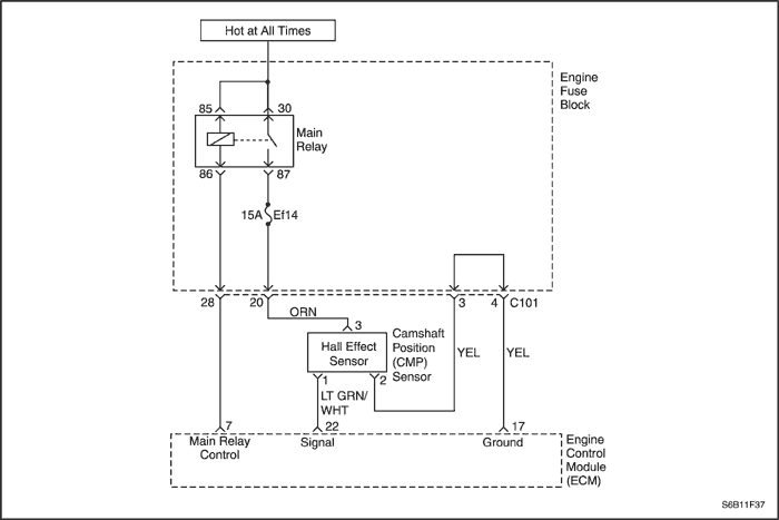
The Camshaft Position (CMP) Sensor is used to detect Camshaft position and to have correlation with Crankshaft position so that the ECM can determine which cylinder is ready to be fueled by the injector. The polarity of camshaft sensor signal must be changed only once per crankshaft position.
Conditions for Running the DTC
Conditions for Setting the DTC
- No transition of CMP signal between teeth 25 and 33 and change in polarity.
Action Taken When the DTC Sets
- The Malfunction Indicator Lamp (MIL) will illuminate.
- The ECM will record operating conditions at the time the diagnostic fails. The information will be stored in the Freeze Frame and Failure Records buffers.
- A history DTC is stored.
Conditions for Clearing the MIL/DTC
- The MIL will turn off at the end of three consecutive validation cycles in which the diagnostic runs without a fault.
- A history DTC will clear after 40 warm-up cycles without a fault.
- DTC(s) can be cleared by using the scan tool.
Diagnostic Aids
Check and correct any abnormal engine noise before using the diagnostic table.
Any circuitry that is suspected as causing engine noise complaint should be thoroughly checked for the following conditions :
- Backed-out terminals
- Improper mating
- Broken locks
- Improperly formed
- Damaged terminals
- Poor terminal-to-wire connection
- Physical damage to the wiring harness
DTC P0341 - Camshaft Position Sensor Rationality
| Step | Action | Value(s) | Yes | No |
| 1 | Perform the Diagnostic System Check. Is the system check complete? | - | Go to Step 2 | |
| 2 | - Turn the ignition switch to LOCK.
- Disconnect the CMP sensor connector.
- Check for a faulty connector or terminals.
Is the problem found? | - | Go to Step 4 | Go to Step 3 |
| 3 | - Turn the ignition switch to ON.
- Disconnect the ECM connector.
- Inspect the ECM pins and connector for bent or damaged terminals.
- Check the wire between the CMP sensor terminal 1 and ECM connector 22 for an open, short to ground, or short to battery voltage.
- Check the wires between the CMP sensor terminal 2 and ECM connector 17 for an open.
Is the problem found? | - | Go to Step 4 | Go to Step 5 |
| 4 | - Turn the ignition switch to LOCK.
- Repair or replace the wire or the connector.
- Clear any DTCs from the ECM.
- Run the engine.
- Perform the diagnostic system check.
Is the repair complete? | - | System OK | - |
| 5 | - Turn the ignition switch to LOCK.
- Replace the CMP sensor.
- Clear any DTCs from the ECM.
- Run the engine.
- Perform the diagnostic system check.
Does DTC P0341 reset? | - | System OK | Go to Step 6 |
| 6 | - Replace the ECM.
- Run the engine.
- Perform the Diagnostic system check.
Is the replacement complete? | - | Go to Step 7 | - |
| 7 | - Using the scan tool, clear the DTCs.
- Start the engine and idle at normal operating temperature.
- Operate the vehicle within the conditions for setting this DTC as specified in the supporting text.
Does the scan tool indicate that this diagnostic run and passed? | - | Go to Step 8 | - |
| 8 | Check if any additional DTCs are set. Are any DTCs displayed that have not been diagnosed? | - | Go to applicable DTC table | System OK |
Diagnostic Trouble Code (DTC) P0342
Camshaft Position Sensor No Signal
Circuit Description
The Camshaft Position (CMP) Sensor is used to detect Camshaft position and to have correlation with Crankshaft position so that the ECM can determine which cylinder is ready to be fueled by the injector. The polarity of camshaft sensor signal must be changed only once per crankshaft position.
Conditions for Running the DTC
Conditions for Setting the DTC
- No transition of CMP signal between teeth 25 and 33 and no change in polarity.
Action Taken When the DTC Sets
- The Malfunction Indicator Lamp (MIL) will illuminate.
- The ECM will record operating conditions at the time the diagnostic fails. The information will be stored in the Freeze Frame and Failure Records buffers.
- A history DTC is stored.
Conditions for Clearing the MIL/DTC
- The MIL will turn off at the end of three consecutive validation cycles in which the diagnostic runs without a fault.
- A history DTC will clear after 40 warm-up cycles without a fault.
- DTC(s) can be cleared by using the scan tool.
Diagnostic Aids
Check and correct any abnormal engine noise before using the diagnostic table.
Any circuitry that is suspected as causing engine noise complaint should be thoroughly checked for the following conditions :
- Backed-out terminals
- Improper mating
- Broken locks
- Improperly formed
- Damaged terminals
- Poor terminal-to-wire connection
- Physical damage to the wiring harness
DTC P0342 - Camshaft Position Sensor No Signal
| Step | Action | Value(s) | Yes | No |
| 1 | Perform the Diagnostic System Check. Is the system check complete? | - | Go to Step 2 | |
| 2 | - Turn the ignition switch to LOCK.
- Disconnect the CMP sensor connector.
- Check for a faulty connector or terminals.
Is the problem found? | - | Go to Step 4 | Go to Step 3 |
| 3 | - Turn the ignition switch to ON.
- Disconnect the ECM connector.
- Inspect the ECM pins and connector for bent or damaged terminals.
- Check the wire between the CMP sensor terminal 1 and ECM connector 22 for an open, short to ground, or short to battery voltage.
- Check the wires between the CMP sensor terminal 2 and ECM connector 17 for an open.
Is the problem found? | - | Go to Step 4 | Go to Step 5 |
| 4 | - Turn the ignition switch to LOCK.
- Repair or replace the wire or the connector.
- Clear any DTCs from the ECM.
- Run the engine.
- Perform the diagnostic system check.
Is the repair complete? | - | System OK | - |
| 5 | - Turn the ignition switch to LOCK.
- Replace the CMP sensor.
- Clear any DTCs from the ECM.
- Run the engine.
- Perform the diagnostic system check.
Does DTC P0342 reset? | - | System OK | Go to Step 6 |
| 6 | - Replace the ECM.
- Run the engine.
- Perform the Diagnostic system check.
Is the replacement complete? | - | Go to Step 7 | - |
| 7 | - Using the scan tool, clear the DTCs.
- Start the engine and idle at normal operating temperature.
- Operate the vehicle within the conditions for setting this DTC as specified in the supporting text.
Does the scan tool indicate that this diagnostic run and passed? | - | Go to Step 8 | - |
| 8 | Check if any additional DTCs are set. Are any DTCs displayed that have not been diagnosed? | - | Go to applicable DTC table | System OK |
Diagnostic Trouble Code (DTC)
P0351 Ignition Control Circuit 1 and 4 Fault
P0352 Ignition Control Circuit 2 and 3 Fault
Circuit Description
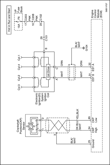
The engine control module (ECM) provides a ground for the electronic spark timing circuit. When the ECM removes the ground path of the ignition primary coil, the magnetic field produced by the coil collapses. The collapsing magnetic field produces a voltage in the secondary coil which fires the spark plug. The circuit between the ECM and the electronic ignition system is monitored for an open circuit, short to voltage, and low voltage. When the ECM detects a problem in the spark timing circuit, it will set a DTC.
Conditions for Running the DTC
Conditions for Setting the DTC
- An open, a short to ground, or a short to battery condition in the ignition signal coil circuit exists.
Action Taken When the DTC Sets
- The Malfunction Indicator Lamp (MIL) will illuminate.
- The ECM will record operating conditions at the time the diagnostic fails. This information will be stored in the Freeze Frame and Failure Records buffers.
- A history DTC is stored.
Conditions for Clearing the MIL/DTC
- The MIL will turn off at the end of a consecutive validation cycle in which the diagnostic runs without a fault.
- A history DTC will clear after 40 warm-up cycles without a fault.
- DTC(s) can be cleared by using the scan tool.
Diagnostic Aids
Check and correct any abnormal engine noise before using the diagnostic table.
Any circuitry that is suspected as causing engine noise complaint should be thoroughly checked for the following conditions :
- Backed-out terminals
- Improper mating
- Broken locks
- Improperly formed
- Damaged terminals
- Poor terminal-to-wire connection
- Physical damage to the wiring harness
DTC P0351 - Ignition Control Circuit 1 and 4 Fault
DTC P0352 - Ignition Control Circuit 2 and 3 Fault
| Step | Action | Value(s) | Yes | No |
| 1 | Perform the Diagnostic System Check. Is the system check complete? | - | Go to Step 2 | |
| 2 | Check for a faulty connection or a damaged terminal at the ignition coil and repair as needed. Is the repair complete? | - | Go to Step 8 | Go to Step 3 |
| 3 | Check for a faulty connection or a damaged terminal at the engine control module(ECM) connector and repair as needed. Is the repair complete? | - | Go to Step 8 | Go to Step 4 |
| 4 | - Turn the ignition switch to LOCK.
- Disconnect the ECM connector.
- Check the ignition control circuit for a short to ground and repair as needed.
Is the repair complete? | - | Go to Step 8 | Go to Step 5 |
| 5 | Check the ignition control circuit for a short to voltage and repair as necessary. Is the repair complete? | - | Go to Step 8 | Go to Step 6 |
| 6 | Check for an open in the ignition control circuit and repair as needed. Is the repair complete? | - | Go to Step 8 | Go to Step 7 |
| 7 | Replace the ECM. Is the replacement complete? | - | Go to Step 8 | - |
| 8 | - Using the scan tool, clear the Diagnostic Trouble Codes(DTCs).
- Start the engine and Idle at normal operating temperature.
- Operate the vehicle within the conditions for setting this DTC as specified in the supporting text.
Does the scan tool indicate that this diagnostic ran and passed? | - | Go to Step 9 | Go to Step 2 |
| 9 | Check if any additional DTCs are set. Are any DTCs displayed that have not been diagnosed? | - | Go to applicable DTC table | System OK |
Diagnostic Trouble Code (DTC)
P0400 Exhaust Gas Recirculation Flow Out of Limit
P0401 Exhaust Gas Recirculation Blocked
Circuit Description
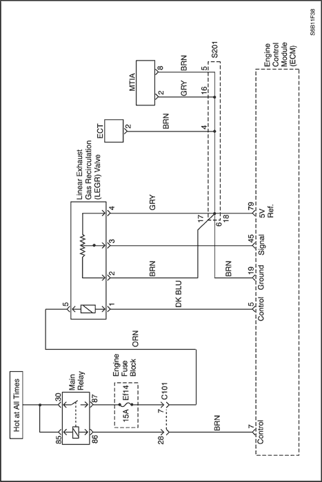
A voltage is provided to the exhaust gas recirculation (EGR) valve by the ignition voltage circuit through a fuse. Ground is provided to the EGR valve on the control circuit by a low side driver within the engine control module (ECM). The ECM monitors the position of the EGR pintle through the EGR position sensor. The EGR position sensor sends a feedback voltage on the signal circuit to the ECM. This voltage varies depending on the position of the EGR valve pintle. The ECM interprets this voltage as the position of the EGR valve pintle.
The engine control module (ECM) performs a flow test on the exhaust gas recirculation (EGR) system during deceleration. The ECM does this by momentarily commanding the EGR valve to open while monitoring the signal of the manifold absolute pressure (MAP) sensor and the EGR position sensor. If the MAP signal is incorrect for the EGR pintle position, the ECM records the amount of MAP difference that was detected and adjusts a calibrated fail counter towards a calibrated fail threshold level. The number of EGR flow tests required to exceed the fail threshold may vary according to the amount of detected EGR flow error.
Normally, the ECM will only allow one EGR flow test during an ignition cycle. To aid in verifying a repair, the ECM will allow multiple EGR flow tests following a code clear event.
Conditions for Running the DTC
- Engine is running.
- EGR is in operation condition.
- No EGR failure exists.
- Engine speed is between 2048 rpm and 2304 rpm.
- Mass air flow is between 98 and 152 mg/tdc.
- Engine coolant temperture is higher than 81.75°C (179.15°F).
Conditions for Setting the DTC
(P0400)
- EGR adaptation value is greater than 2.008 or less than 0.141.
(P0401)
- Difference between EGR rate and lambda is 1.758% or less.
Action Taken When the DTC Sets
- The Malfunction Indicator Lamp (MIL) will illuminate.
- The ECM will record operating conditions at the time the diagnostic fails. The information will be stored in the freeze frame and failure records buffers.
- A history DTC is stored.
Conditions for Clearing the MIL/DTC
- The MIL will turn off at the end of 3 consecutive validation cycles in which the diagnostic runs without a fault.
- A history DTC will clear after 40 warm up cycles without a fault.
- DTC(s) can be cleared by using the scan tool.
Test Description
The numbers below refer to the step numbers on the diagnostic table.
- MAP sensor faults must be diagnosed first. A skewed MAP sensor reading could cause this DTC to set.
- An engine mechanical condition may cause the engine to operate poorly, which could cause a low vacuum condition.
DTC P0400 – Exhaust Gas Recirculation Flow Out of Limit
DTC P0401 – Exhaust Gas Recirculation Blocked
| Step | Action | Value(s) | Yes | No |
| 1 | Did you perform the Diagnostic System Check? | - | Go to Step 2 | |
| 2 | - Observe the Freeze Frame/Failure Records for this DTC.
- Turn OFF the ignition for 30 seconds.
- Start the engine.
- Operate the vehicle within the Conditions for Running the DTC. You may also operate the vehicle within the conditions that you observed from the Freeze Frame/Failure Records.
Did the DTC fail this ignition? | - | Go to Step 3 | |
| 3 | Is DTC P0107 or P0108 also set? | - | Go to applicable DTC table | Go to Step 4 |
| 4 | Inspect the exhaust gas recirculation (EGR) system for the following conditions: - Incorrect EGR valve for engine application.
- A vacuum leak between the EGR valve and the intake manifold.
- Signs of external leakage usually indicated by carbon buildup around the mating surfaces of the components or an audible exhaust noise.
- Restrictions in the passages or EGR valve caused by carbon deposits or casting flash.
Did you find and correct the condition? | - | Go to Step 9 | Go to Step 5 |
| 5 | Inspect for leaks or restrictions at the manifold absolute pressure (MAP) sensor. Did you find and correct the condition? | - | Go to Step 9 | Go to Step 6 |
| 6 | Inspect the exhaust system for the following conditions: - Leaks caused by damage to the exhaust components.
- Restrictions that can cause excessive back pressure and low engine vacuum - Restrictions may be caused by aftermarket equipment or damage to the exhaust components.
- Modification of original equipment manufacture (OEM) parts.
Did you find and correct the condition? | - | Go to Step 9 | Go to Step 7 |
| 7 | Inspect for the following engine mechanical conditions: - The correct installation of the timing belt.
- Worn piston rings. Worn camshaft.
- Worn camshaft.
- Other worn or damaged engine components.
Did you find and correct the condition? | - | Go to Step 9 | Go to Step 8 |
| 8 | Replace the EGR valve. Did you complete the replacement? | - | Go to Step 9 | - |
| 9 | - Clear the DTCs with a scan tool.
- Turn OFF the ignition for 30 seconds.
- Start the engine.
- Operate the vehicle within the Conditions for Running the DTC. You may also operate the vehicle within the conditions that you observed from the Freeze Frame/Failure Records.
Did the DTC fail this ignition? | - | Go to Step 2 | Go to Step 10 |
| 10 | Check if any additional DTCs are set. Are there any DTCs that have not been diagnosed? | - | Go to applicable DTC table | System OK |
Diagnostic Trouble Code (DTC) P0403
EGR Valve Circuit Failure
Circuit Description
A voltage is provided to the exhaust gas recirculation (EGR) valve by the ignition voltage circuit through a fuse. Ground is provided to the EGR valve on the control circuit by a low side driver within the engine control module (ECM). The ECM monitors the voltage on the control circuit of the EGR valve to determine if a failure is present. If ECM detects the voltage on the control circuit of the EGR valve is low while the valve is not commanded or high while the valve is being commanded, DTC P0403 sets.
Conditions for Running the DTC
Conditions for Setting the DTC
- A short to ground, an open, or a short to battery voltage condition in the EGR system exists.
Action Taken When the DTC Sets
- The Malfunction Indicator Lamp (MIL) will illuminate.
- The ECM will record operating conditions at the time the diagnostic fails. The information will be stored in the freeze frame and failure records buffers.
- A history DTC is stored.
Conditions for Clearing the MIL/DTC
- The MIL will turn off at the end of 3 consecutive validation cycles in which the diagnostic runs without a fault.
- A history DTC will clear after 40 warm up cycles without a fault.
- DTC(s) can be cleared by using the scan tool.
DTC P0403 – EGR Valve Circuit Failure
| Step | Action | Value(s) | Yes | No |
| 1 | Did you perform the Diagnostic System Check? | - | Go to Step 2 | |
| 2 | - Turn ON the ignition, with the engine OFF.
- Observe the EGR Position Sensor parameter with a scan tool.
Is the voltage less than the specified value? | 0.80 V | Go to Step 3 | Go to Step 5 |
| 3 | - Command the EGR valve from 0% to 100% with a scan tool.
- Observe the EGR Position Sensor parameter with a scan tool.
Is the voltage more than the specified value? | 4.20 V | Go to Step 4 | Go to Step 5 |
| 4 | - Observe the Freeze Frame/Failure Records data for this DTC.
- Turn OFF the ignition for 30 seconds.
- Operate the vehicle within the Conditions for Running the DTC. You may also operate the vehicle within the conditions that you observed from the Freeze Frame/Failure Records.
Did the DTC fail this ignition? | - | Go to Step 5 | |
| 5 | - Turn OFF the ignition.
- Disconnect the exhaust gas recirculation (EGR) valve.
- Turn ON the ignition, with the engine OFF.
- Connect a test lamp between the ignition voltage circuit of the EGR valve and a good ground.
Does the test lamp illuminate? | - | Go to Step 6 | Go to Step 13 |
| 6 | Connect a test lamp from the ignition voltage circuit to the control circuit of the EGR valve. Does the test lamp illuminate? | - | Go to Step 10 | Go to Step 7 |
| 7 | - Connect a test lamp from the ignition voltage circuit to the control circuit of the EGR valve.
- Command the EGR valve to 100 percent.
Does the test lamp illuminate? | - | Go to Step 8 | Go to Step 10 |
| 8 | - Turn OFF the ignition.
- Disconnect the fuse that supplies ignition voltage to the EGR valve.
- Measure the resistance of the ignition voltage circuit of the EGR valve from the fuse terminal to the harness connector terminal of the EGR valve.
Is the resistance less than the specified value? | 3 ohms | Go to Step 9 | Go to Step 13 |
| 9 | - Turn ON the ignition, with the engine OFF.
- Probe the control circuit of the EGR valve with a test lamp connected to battery positive voltage.
- Command the EGR valve to 100%.
- Measure the voltage from the probe of the test lamp to a good ground.
Is the voltage less than the specified value? | 0.5 V | Go to Step 11 | Go to Step 10 |
| 10 | Test the control circuit of the EGR valve for one of the following conditions: - An open
- A short to ground
- A short to voltage
- High resistance
Did you find and correct the condition? | - | Go to Step 16 | Go to Step 12 |
| 11 | Test the EGR valve for the following: - Excessive deposits on the EGR valve pintle that may interfere with the EGR valve pintle extending completely or cause the pintle to stick.
- An intermittent and poor connection at the EGR valve.
Did you find and correct the condition? | - | Go to Step 16 | Go to Step 14 |
| 12 | Test for an intermittent and for a poor connection at the engine control module (ECM). Did you find and correct the condition? | - | Go to Step 16 | Go to Step 15 |
| 13 | Repair the ignition voltage circuit of the EGR valve for one of the following conditions: - An open
- A short to ground
- High resistance
Did you complete the repair? | - | Go to Step 16 | - |
| 14 | Replace the EGR valve. Did you complete the replacement? | - | Go to Step 16 | - |
| 15 | Replace the ECM. Did you complete the replacement? | - | Go to Step 16 | - |
| 16 | - Clear the DTCs with a scan tool.
- Turn OFF the ignition for 30 seconds.
- Start the engine.
- Operate the vehicle within the Conditions for Running the DTC. You may also operate the vehicle within the conditions that you observed from the Freeze Frame/Failure Records.
Did the DTC fail this ignition? | - | Go to Step 2 | Go to Step 17 |
| 17 | Check if any additional DTC are set. Are there any DTCs that have not been diagnosed? | - | Go to applicable DTC table | System OK |
Diagnostic Trouble Code (DTC) P0404
Exhaust Gas Recirculation Valve Failure
Circuit Description
The engine control module (ECM) monitors the position of the exhaust gas recirculation (EGR) valve through the EGR valve position sensor. The EGR valve position sensor sends a feedback voltage on the signal circuit to the ECM. This voltage varies depending on the position of the EGR valve. The ECM interprets this voltage as the position of the EGR valve. If the ECM detects a difference between the actual EGR position and the commanded EGR position, DTC P0404 sets.
Conditions for Running the DTC
- Engine is running.
- EGR is in operation condition.
- No EGR failure exists.
- Engine speed is between 2048 rpm and 2304 rpm.
- Mass air flow is between 98 and 152 mg/tdc.
- Engine coolant temperature is higher than 81.75°C (179.15°F).
Conditions for Setting the DTC
- EGR potentiometer low value learnt is lower than 0.1613 V or higher than 4.9022V.
Action Taken When the DTC Sets
- The Malfunction Indicator Lamp (MIL) will illuminate.
- The ECM will record operating conditions at the time the diagnostic fails. The information will be stored in the freeze frame and failure records buffers.
- A history DTC is stored.
Conditions for Clearing the MIL/DTC
- The MIL will turn off at the end of 3 consecutive validation cycles in which the diagnostic runs without a fault.
- A history DTC will clear after 40 warm up cycles without a fault.
- DTC(s) can be cleared by using the scan tool.
DTC P0404 – Exhaust Gas Recirculation Valve Failure
| Step | Action | Value(s) | Yes | No |
| 1 | Did you perform the Diagnostic System Check? | - | Go to Step 2 | |
| 2 | Is DTC P0403, P0405 or P0406 also set? | - | Go to applicable DTC table | Go to Step 3 |
| 3 | - Turn ON the ignition, with the engine OFF.
- Observe the EGR Position Sensor parameter with a scan tool.
Is the voltage less than the specified value? | 0.80 V | Go to Step 4 | Go to Step 6 |
| 4 | - Command the EGR valve from 0% to 100% with a scan tool.
- Observe the EGR Position Sensor parameter with a scan tool.
Is the voltage more than the specified value? | 4.20 V | Go to Step 5 | Go to Step 6 |
| 5 | - Observe the Freeze Frame/Failure Records data for this DTC.
- Turn OFF the ignition for 30 seconds.
- Operate the vehicle within the Conditions for Running the DTC. You may also operate the vehicle within the conditions that you observed from the Freeze Frame/Failure Records.
Did the DTC fail this ignition? | - | Go to Step 6 | |
| 6 | - Turn OFF the ignition.
- Disconnect the exhaust gas recirculation (EGR) valve.
- Turn ON the ignition, with the engine OFF.
- Connect a test lamp between the 5-volt reference circuit and the low reference circuit of the EGR valve position sensor.
Does the test lamp illuminate? | - | Go to Step 8 | Go to Step 7 |
| 7 | Connect a test lamp between the 5-volt reference circuit of the EGR valve position sensor and a good ground. Does the test lamp illuminate? | - | Go to Step 13 | Go to Step 12 |
| 8 | - Connect a 3-ampere fused jumper wire between the signal circuit and the low reference circuit of the EGR valve position sensor.
- Observe the EGR Position Sensor parameter on the scan tool.
Is the parameter less than the specified value? | 0.05 V | Go to Step 9 | Go to Step 11 |
| 9 | - Turn OFF the ignition.
- Disconnect the fuse that supplies ignition voltage to the EGR valve.
- Measure the resistance of the ignition voltage circuit of the EGR valve from the fuse terminal to the harness connector terminal of the EGR valve.
Is the resistance less than the specified value? | 3 ohms | Go to Step 10 | Go to Step 17 |
| 10 | - Turn ON the ignition, with the engine OFF.
- Probe the control circuit of the EGR valve with a test lamp connected to battery positive voltage.
- Command the EGR valve to 100%.
- Measure the voltage from the probe of the test lamp to a good ground.
Is the voltage less than the specified value? | 0.3 V | Go to Step 15 | Go to Step 14 |
| 11 | Test the signal circuit of the EGR valve position sensor for a high resistance. Did you find and correct the condition? | - | Go to Step 20 | Go to Step 16 |
| 12 | Test the 5-volt reference circuit of the EGR valve position sensor for an open or high resistance. Did you find and correct the condition? | - | Go to Step 20 | Go to Step 16 |
| 13 | Test the low reference circuit of the EGR valve position sensor for an open or high resistance. Did you find and correct the condition? | - | Go to Step 20 | Go to Step 16 |
| 14 | Test the control circuit of the EGR valve for an open or high resistance. Did you find and correct the condition? | - | Go to Step 20 | Go to Step 16 |
| 15 | Test the EGR valve for the following: - Excessive deposits on the EGR valve pintle that may interfere with the EGR valve pintle extending completely or cause the pintle to stick.
- An intermittent and poor connection at the EGR valve.
Did you find and correct the condition? | - | Go to Step 20 | Go to Step 18 |
| 16 | Test for an intermittent and for a poor connection at the engine control module (ECM). Did you find and correct the condition? | - | Go to Step 20 | Go to Step 19 |
| 17 | Repair the high resistance in the ignition voltage circuit of the EGR valve. Did you complete the repair? | - | Go to Step 20 | - |
| 18 | Replace the EGR valve. Did you complete the replacement? | - | Go to Step 20 | - |
| 19 | Replace the ECM. Did you complete the replacement? | - | Go to Step 20 | - |
| 20 | - Clear the DTCs with a scan tool.
- Turn OFF the ignition for 30 seconds.
- Start the engine.
- Operate the vehicle within the Conditions for Running the DTC. You may also operate the vehicle within the conditions that you observed from the Freeze Frame/Failure Records.
Did the DTC fail this ignition? | - | Go to Step 2 | Go to Step 21 |
| 21 | Check if any additional DTCs are set. Are there any DTCs that have not been diagnosed? | - | Go to applicable DTC table | System OK |
Diagnostic Trouble Code (DTC) P0405
EGR Feedback Circuit Low Voltage
Circuit Description
The engine control module (ECM) monitors the position of the exhaust gas recirculation (EGR) valve through the EGR valve position sensor. The EGR valve position sensor sends a feedback voltage on the signal circuit to the ECM. The EGR position sensor voltage varies depending on the position of the EGR valve. If the voltage on the signal circuit of the EGR valve position sensor is less than a calibrated value, DTC P0405 sets.
Conditions for Running the DTC
Conditions for Setting the DTC
- The ECM detects that the EGR position voltage is less than 0.0098 V.
Action Taken When the DTC Sets
- The Malfunction Indicator Lamp (MIL) will illuminate.
- The ECM will record operating conditions at the time the diagnostic fails. The information will be stored in the freeze frame and failure records buffers.
- A history DTC is stored.
Conditions for Clearing the MIL/DTC
- The MIL will turn off at the end of 3 consecutive validation cycles in which the diagnostic runs without a fault.
- A history DTC will clear after 40 warm up cycles without a fault.
- DTC(s) can be cleared by using the scan tool.
DTC P0405 – EGR Feedback Circuit Low Voltage
| Step | Action | Value(s) | Yes | No |
| 1 | Did you perform the Diagnostic System Check? | - | Go to Step 2 | |
| 2 | - Start the engine.
- Allow the engine to idle for 30 seconds.
- Observe the DTC Information with a scan tool.
Did DTC P0405 fail this ignition? | - | Go to Step 4 | Go to Step 3 |
| 3 | - Observe the Freeze Frame/Failure Records for this DTC.
- Turn OFF the ignition for 30 seconds.
- Operate the vehicle within the Conditions for Running the DTC. You may also operate the vehicle within the conditions that you observed from the Freeze Frame/Failure Records.
Did the DTC fail this ignition? | - | Go to Step 4 | |
| 4 | - Turn OFF the ignition.
- Disconnect the harness connector of the exhaust gas recirculation (EGR) valve.
- Turn ON the ignition, with the engine OFF.
- Observe the EGR Position Sensor parameter with a scan tool.
Is the voltage more then the specified value? | 4.9 V | Go to Step 5 | Go to Step 9 |
| 5 | Connect a test lamp between the 5-volt reference circuit of the EGR valve position sensor and a good ground. Does the test lamp illuminate? | - | Go to Step 10 | Go to Step 6 |
| 6 | While the test lamp is connected to the 5-volt reference circuit, disconnect the harness connector of the following sensors one at a time: - Manifold Absolute Pressure (MAP) sensor.
- Throttle Position (TP) Sensor.
- A/C Pressure Sensor.
- Fuel Level Sensor.
Does the test lamp illuminate? | - | Go to Step 12 | Go to Step 7 |
| 7 | Test the 5-volt reference circuit of the following sensors for a short to ground: - Manifold Absolute Pressure (MAP) sensor.
- Throttle Position (TP) Sensor.
- A/C Pressure Sensor.
- Fuel Level Sensor.
Did you find and correct the condition? | - | Go to Step 15 | Go to Step 8 |
| 8 | Test the 5-volt reference circuit of the EGR valve position sensor for one of the following conditions: - An open.
- High resistance.
- A short to ground.
Did you find and correct the condition? | - | Go to Step 15 | Go to Step 11 |
| 9 | Test the signal circuit of the EGR valve position sensor for a short to ground. Did you find and correct the condition? | - | Go to Step 15 | Go to Step 11 |
| 10 | Test for an intermittent and poor connection at the EGR valve. Did you find and correct the condition? | - | Go to Step 15 | Go to Step 13 |
| 11 | Test for an intermittent and poor connection at the engine control module (ECM). Did you find and correct the condition? | - | Go to Step 15 | Go to Step 14 |
| 12 | Replace the appropriate sensor. Did you complete the replacement? | - | Go to Step 15 | - |
| 13 | Replace the EGR valve. Did you complete the replacement? | - | Go to Step 15 | - |
| 14 | Replace the ECM. Did you complete the replacement? | - | Go to Step 15 | - |
| 15 | - Clear the DTCs with a scan tool.
- Turn OFF the ignition for 30 seconds.
- Start the engine.
- Operate the vehicle within the Conditions for Running the DTC. You may also operate the vehicle within the conditions that you observed from the Freeze Frame/Failure Records.
Did the DTC fail this ignition? | - | Go to Step 2 | Go to Step 16 |
| 16 | Check if any additional DTCs are set. Are there any DTCs that have not been diagnosed? | - | Go to applicable DTC table | System OK |
Diagnostic Trouble Code (DTC) P0406
EGR Feedback Circuit High Voltage
Circuit Description
The engine control module (ECM) monitors the position of the exhaust gas recirculation (EGR) valve through the EGR valve position sensor. The EGR valve position sensor sends a feedback voltage on the signal circuit to the ECM. The EGR position sensor voltage varies depending on the position of the EGR valve. If the voltage on the signal circuit of the EGR valve position sensor is pulled higher than a calibrated value, DTC P0406 sets.
Conditions for Running the DTC
Conditions for Setting the DTC
- The ECM detects that the EGR position voltage is more than 4.9022 V.
Action Taken When the DTC Sets
- The Malfunction Indicator Lamp (MIL) will illuminate.
- The ECM will record operating conditions at the time the diagnostic fails. The information will be stored in the freeze frame and failure records buffers.
- A history DTC is stored.
Conditions for Clearing the MIL/DTC
- The MIL will turn off at the end of 3 consecutive validation cycles in which the diagnostic runs without a fault.
- A history DTC will clear after 40 warm up cycles without a fault.
- DTC(s) can be cleared by using the scan tool.
DTC P0406 – EGR Feedback Circuit High Voltage
| Step | Action | Value(s) | Yes | No |
| 1 | Did you perform the Diagnostic System Check? | - | Go to Step 2 | |
| 2 | - Start the engine.
- Allow the engine to idle for 30 seconds.
- Observe the DTC Information with a scan tool.
Did DTC P0406 fail this ignition? | - | Go to Step 4 | Go to Step 3 |
| 3 | - Observe the Freeze Frame/Failure Records for this DTC.
- Turn OFF the ignition for 30 seconds.
- Operate the vehicle within the Conditions for Running the DTC. You may also operate the vehicle within the conditions that you observed from the Freeze Frame/Failure Records.
Did the DTC fail this ignition? | - | Go to Step 4 | |
| 4 | - Turn OFF the ignition.
- Disconnect the harness connector of the exhaust gas recirculation (EGR) valve.
- Turn ON the ignition, with the engine OFF.
- Measure the voltage between the 5-volt reference circuit of the EGR valve position sensor and a good ground.
Is the voltage less than the specified value? | 5.2 V | Go to Step 5 | Go to Step 8 |
| 5 | Connect a test lamp between the 5-volt reference circuit and the low reference circuit of the EGR valve position sensor. Does the test lamp illuminate? | - | Go to Step 6 | Go to Step 11 |
| 6 | Measure the voltage between the signal circuit of the EGR valve position sensor and a good ground. Is the voltage less than the specified value? | 5 V | Go to Step 7 | Go to Step 10 |
| 7 | - Connect a 3-ampere fused jumper wire between the signal circuit and the low reference circuit of the EGR valve position sensor.
- Observe the EGR Position Sensor parameter on the scan tool.
Is the parameter less than the specified value? | 0.05 V | Go to Step 12 | Go to Step 10 |
| 8 | Test the 5-volt reference circuit of the following sensors for a short to voltage: - Manifold Absolute Pressure (MAP) sensor.
- Throttle Position (TP) Sensor.
- A/C Pressure Sensor.
- Fuel Level Sensor.
Did you find and correct the condition? | - | Go to Step 16 | Go to Step 9 |
| 9 | Test the 5-volt reference circuit of the EGR valve position sensor for a short to voltage. Did you find and correct the condition? | - | Go to Step 16 | Go to Step 13 |
| 10 | Test the signal circuit of the EGR valve position sensor for one of the following conditions: - An open.
- High resistance.
- Short to voltage.
Did you find and correct the condition? | - | Go to Step 16 | Go to Step 13 |
| 11 | Test the low reference circuit of the EGR valve position sensor for an open or high resistance. Did you find and correct the condition? | - | Go to Step 16 | Go to Step 13 |
| 12 | Test for an intermittent and poor connection at the EGR valve. Did you find and correct the condition? | - | Go to Step 16 | Go to Step 14 |
| 13 | Test for an intermittent and poor connection at the engine control module (ECM). Did you find and correct the condition? | - | Go to Step 16 | Go to Step 15 |
| 14 | Replace the EGR valve. Did you complete the replacement? | - | Go to Step 16 | - |
| 15 | Replace the ECM. Did you complete the replacement? | - | Go to Step 16 | - |
| 16 | - Clear the DTCs with a scan tool.
- Turn OFF the ignition for 30 seconds.
- Start the engine.
- Operate the vehicle within the Conditions for Running the DTC. You may also operate the vehicle within the conditions that you observed from the Freeze Frame/Failure Records.
Did the DTC fail this ignition? | - | Go to Step 2 | Go to Step 17 |
| 17 | Check if any additional DTCs are set. Are there any DTCs that have not been diagnosed? | - | Go to applicable DTC table | System OK |
 | |  | |
| © Copyright Chevrolet Europe. All rights reserved |