Diagnostic Trouble Code (DTC) P0420
Lower Catalyst Efficiency
Circuit Description
In order to control exhaust emissions of Hydrocarbons (HC), Carbon Monoxide (CO) and Nitrogen Oxide (NOx), a Three-Way Catalytic Converter (TWC) is used. The catalyst within the converter promotes a chemical reaction which oxidizes the HC and CO present in the exhaust gas, converting them into harmless water vapor and carbon dioxide, it also reduces NOx, converting it into nitrogen. The catalytic converter also has the ability to store oxygen.
The Engine Control Module (ECM) has the capability to monitor this process using a Heated Oxygen Sensor 2 (HO2S2) located in the exhaust stream past the TWC. The HO2S2 produces an output signal which indicates the oxygen storage capacity of the catalyst; this in turn indicates the catalyst's ability to convert exhaust emissions effectively. The ECM monitors the catalyst efficiency by first allowing the catalyst to heat up, waiting for a stabilization period while the engine is idling, and then adding and removing fuel while monitoring the reaction of the HO2S2. When the catalyst is functioning properly, the HO2S2 response to the extra fuel is slow compared to the HO2S1. When the HO2S2 response is close to that of the HO2S1, the Oxygen storage capability or efficiency of the catalyst is considered to be bad, and the Malfunction Indicator Lamp (MIL) will illuminate.
Conditions for Running the DTC
- Vehicle is in closed loop condition.
- Engine coolant temperature (ECT) is higher than 78°C (172.4°F).
- Mass air flow is between 15 and 30 kg/h.
- Engine speed is between 1792 rpm and 2304 rpm.
- Vehicle speed is between 45 km/h and 56 km/h.
- Deviation of air flow is less than 10 kg/h.
- Predicted catalyst temperature is between 300°C (572°F) and 800°C (1472°F).
- Engine is running more than 60 seconds.
- None of the DTCs related to HO2S, Misfire, ECT sensor, CKP sensor, CMP sensor, VSS, MAT sensor, TP sensor, MITA, EGR, fuel trim, or CAN communication exist.
Conditions for Setting the DTC
- Filtered HO2S2 signal value is higher than 101.
Action Taken When the DTC Sets
- The Malfunction Indicator Lamp (MIL) will illuminate.
- The ECM will record operating conditions at the time the diagnostic fails. The information will be stored in the Freeze Frame and Failure Records buffers.
- A history DTC is stored.
Conditions for Clearing the MIL/DTC
- The MIL will turn off at the end of three consecutive validation cycles in which the diagnostic runs without a fault.
- A history DTC will clear after 40 warm-up cycles without a fault.
- DTC(s) can be cleared by using the scan tool.
Diagnostic Aids
The catalyst test may abort due to a change in the engine load. Do not change the engine load (i.e. A/C, coolant fan, heater motor) while a catalyst test is in progress.
An intermittent problem may be caused by a poor connection, rubbed-through wire insulation, or a wire that is broken inside the insulation.
Any circuitry, that is suspected as causing the intermittent complaint, should be thoroughly checked for the following conditions:
- Backed-out terminals
- Improper mating
- Broken locks
- Improperly formed
- Damaged terminals
- Poor terminal-to-wire connection.
DTC P0420 - Lower Catalyst Efficiency
| Step | Action | Value(s) | Yes | No |
| 1 | Perform the Diagnostic System Check. Was the check performed? | - | Go to Step 2 | |
| 2 | - Install a scan tool to the Data link Connector (DLC).
- Turn the ignition ON.
Are any component Diagnostic Trouble Codes (DTCs) set? | - | Go to applicable DTC table | Go to Step 3 |
| 3 | Visually/physically check the following: - Exhaust system for a leak.
- Heated Oxygen Sensor (HO2S).
Is a problem found? | - | Go to Step 4 | Go to Step 5 |
| 4 | Repair the exhaust system as needed. Is the repair complete? | - | Go to Step 6 | - |
| 5 | Replace the Three Way Catalytic Converter (TWC). Is the repair complete? | - | Go to Step 6 | - |
| 6 | - Using the scan tool, clear the Diagnostic Trouble Codes (DTCs).
- Start the engine and idle at normal operating temperature.
- Operate the vehicle within the Conditions for setting this DTC as specified in the supporting text.
Does the scan tool indicate that this diagnostic has run and passed? | - | Go to Step 7 | Go to Step 2 |
| 7 | Check if any additional DTCs are set. Are any DTCs displayed that have not been diagnosed? | - | Go to applicable DTC table | System OK |


Diagnostic Trouble Code (DTC)
P0444 EVAP Purge Control Circuit No Signal
P0445 EVAP Purge Control Circuit Fault
Circuit Description
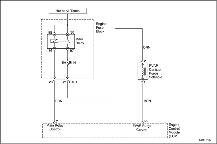
An ignition voltage is supplied directly to the evaporative emissions (EVAP) purge valve. The control module controls the EVAP purge valve by grounding the control circuit via an internal switch called a driver. The primary function of the driver is to supply ground for the controlled component. The control module monitors the status of the driver. If the control module detects an incorrect voltage for the commanded state of the driver, a DTC sets.
Conditions for Running the DTC
Conditions for Setting the DTC
(P0444)
- The ECM detects a line break status in the purge solenoid circuit.
(P0445)
- The ECM detects a short to battery or a short to ground status in the purge solenoid circuit.
Action Taken When the DTC Sets
- The Malfunction Indicator Lamp (MIL) will illuminate.
- The ECM will record operating conditions at the time the diagnostic fails. The information will be stored in the freeze frame and failure records buffers.
- A history DTC is stored.
Conditions for Clearing the MIL/DTC
- The MIL will turn off at the end of 3 consecutive validation cycles in which the diagnostic runs without a fault.
- A history DTC will clear after 40 warm up cycles without a fault.
- DTC(s) can be cleared by using the scan tool.
Test Description
The numbers below refer to the step numbers on the diagnostic table.
- This step tests if the concern is active. The EVAP purge valve is pulse width modulated (PWM). When the purge valve is commanded to 50%, you should hear or feel a clicking. The clicking should stop when the EVAP purge valve is commanded to 0%. The rate at which the valve cycles should increase as the commanded state is increased. The rate should decrease when the commanded state is decreased. Repeat the commands as necessary.
- This step tests if a ground is constantly being applied to the EVAP purge valve.
- This step verifies that the ECM is providing ground to the EVAP purge valve.
DTC P0444 – EVAP Purge Control Circuit No Signal
DTC P0445 – EVAP Purge Control Circuit Fault
| Step | Action | Value(s) | Yes | No |
| 1 | Did you perform the Diagnostic System Check? | - | Go to Step 2 | |
| 2 | - Turn ON the ignition, with the engine OFF.
- With a scan tool, command the EVAP purge valve to 50% and then to 0%.
Do you hear or feel a clicking from the EVAP purge valve when the valve is commanded to 50 %? | - | Go to Step 3 | Go to Step 4 |
| 3 | - Observe the Freeze Frame/Failure Records for this DTC.
- Turn OFF the ignition for 30 seconds.
- Start the engine.
- Operate the vehicle within the Conditions for Running the DTC. You may also operate the vehicle within the conditions that you observed from the Freeze Frame/Failure Records.
Did the DTC fail this ignition? | - | Go to Step 4 | |
| 4 | - Turn OFF the ignition.
- Disconnect the EVAP purge valve harness connector.
- Turn ON the ignition, with the engine OFF.
- Probe the ignition voltage circuit at the EVAP purge valve harness connector with a test lamp connected to a good ground.
Does the test lamp illuminate? | - | Go to Step 5 | Go to Step 11 |
| 5 | - Connect a test lamp between the control circuit and the ignition voltage circuit of the EVAP purge valve harness connector.
- With a scan tool, command the EVAP purge valve to 0 %.
Is the test lamp Illuminated? | - | Go to Step 8 | Go to Step 6 |
| 6 | With a scan tool command the EVAP purge valve to 50% Does the test lamp illuminate when the EVAP purge valve is commanded to 50%? | - | Go to Step 9 | Go to Step 7 |
| 7 | Test the control circuit of the EVAP purge valve for an open or for a short to voltage. Did you find and correct the condition? | - | Go to Step 14 | Go to Step 10 |
| 8 | Test the control circuit of the EVAP purge valve for a short to ground. Did you find and correct the condition? | - | Go to Step 14 | Go to Step 13 |
| 9 | Inspect for poor connections at the EVAP purge valve. Did you find and correct the condition? | - | Go to Step 14 | Go to Step 12 |
| 10 | Inspect for poor connections at the ECM. Did you find and correct the condition? | - | Go to Step 14 | Go to Step 13 |
| 11 | Repair the ignition voltage circuit of the EVAP purge valve. Did you complete the repair? | - | Go to Step 14 | - |
| 12 | Replace the EVAP purge valve. Did you complete the replacement? | - | Go to Step 14 | - |
| 13 | Replace the ECM. Did you complete the replacement? | - | Go to Step 14 | - |
| 14 | - Clear the DTCs with a scan tool.
- Turn OFF the ignition for 30 seconds.
- Start the engine.
- Operate the vehicle within the Conditions for Running the DTC. You may also operate the vehicle within the conditions that you observed from the Freeze Frame/Failure Records.
Did the DTC fail this ignition? | - | Go to Step 2 | Go to Step 15 |
| 15 | Check if any additional DTSs are set. Does the scan tool display any DTCs that you have not diagnosed? | - | Go to applicable DTC table | System OK |
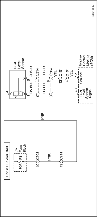
Diagnostic Trouble Code (DTC) P0462
Fuel Level Sensor Low Voltage
Circuit Description
The fuel level sensor changes resistance based on fuel level. The fuel level sensor has a signal circuit and a ground circuit. The engine control module (ECM) applies 5 volts on the signal circuit to the sensor. The ECM monitors the changes in this voltage caused by changes in the resistance of the sensor in order to determine fuel level.
When the fuel tank is full, the sensor resistance is low, and the ECM signal voltage is high. When the fuel tank is empty, the sensor resistance is high, and the signal voltage is low.The ECM uses inputs from the fuel level sensor in order to calculate the total fuel percentage remaining in the fuel tank. The ECM uses the fuel level information for the evaporative emission (EVAP) and misfire diagnostics. The fuel level information is sent to the instrument panel cluster (IPC).
If the ECM detects a signal voltage lower than the operating range of the sensor, this DTC sets.
Conditions for Running the DTC
Conditions for Setting the DTC
- Fuel level sensor signal voltage is lower than 0.2004 V.
Action Taken When the DTC Sets
- The Malfunction Indicator Lamp (MIL) will not illuminate.
- The ECM will record operating conditions at the time the diagnostic fails. The information will be stored in the freeze frame and failure records buffers.
Conditions for Clearing the MIL/DTC
- A history DTC will clear after 40 warm up cycles without a fault.
- DTC(s) can be cleared by using the scan tool.
Diagnostic Aids
Use the Freeze Frame and/or Failure Records data in order to locate an intermittent condition. If you cannot duplicate the DTC, the information included in the Freeze Frame and/or Failure Records data may aid in determining the number of miles since the DTC set. The Fail Counter and Pass Counter can also aid in determining the number of ignition cycles that the diagnostic reported a pass and/or fail. Operate the vehicle within the same freeze frame conditions (RPM, engine load, vehicle speed, temperature, etc.). This will isolate when the DTC failed.
Test Description
The number below refers to the step number on the diagnostic table.
- This step determines if the fault is present.
DTC P0462 – Fuel Level Sensor Low Voltage
| Step | Action | Value(s) | Yes | No |
| 1 | Did you perform the Diagnostic System Check? | - | Go to Step 2 | |
| 2 | - Turn ON the ignition, with the engine OFF.
- Observe the Fuel Level Sensor voltage parameter with a scan tool.
Is the voltage more than the specified value? | 4.25 V | Go to Step 4 | Go to Step 3 |
| 3 | - Observe the Freeze Frame/Failure Records for this DTC.
- Turn OFF the ignition for 30 seconds.
- Start the engine.
- Operate the vehicle within the Conditions for Running the DTC. You may also operate the vehicle within the conditions that you observed from the Freeze Frame/Failure Records.
Did the DTC fail this ignition? | - | Go to Step 4 | |
| 4 | - Turn OFF the ignition.
- Disconnect the fuel level sensor connector.
- Turn ON the ignition, with the engine OFF.
- Observe the Fuel Level Sensor voltage parameter with a scan tool.
Is the voltage less than the specified value? | 4.25 V | Go to Step 6 | Go to Step 5 |
| 5 | Test the signal circuit of the fuel level sensor for an open or a short to ground. Did you find and correct the condition? | - | Go to Step 10 | Go to Step 7 |
| 6 | Test for shorted terminals and poor connections at the fuel level sensor. Did you find and correct the condition? | - | Go to Step 10 | Go to Step 8 |
| 7 | Test for shorted terminals and poor connections at the engine control module (ECM). Did you find and correct the condition? | - | Go to Step 10 | Go to Step 9 |
| 8 | Replace the fuel sender assembly. Did you complete the replacement? | - | Go to Step 10 | - |
| 9 | Replace the control module. Did you complete the replacement? | - | Go to Step 10 | - |
| 10 | - Clear the DTCs with a scan tool.
- Turn OFF the ignition for 30 seconds.
- Start the engine.
- Operate the vehicle within the Conditions for Running the DTC. You may also operate the vehicle within the conditions that you observed from the Freeze Frame/Failure Records.
Did the DTC fail this ignition? | - | Go to Step 2 | Go to Step 11 |
| 11 | Check if any additional DTSs are set. Does the scan tool display any DTCs that you have not diagnosed? | - | Go to applicable DTC table | System OK |
Diagnostic Trouble Code (DTC) P0463
Fuel Level Sensor High Voltage
Circuit Description
The fuel level sensor changes resistance based on fuel level. The fuel level sensor has a signal circuit and a ground circuit. The engine control module (ECM) applies 5 volts on the signal circuit to the sensor. The ECM monitors the changes in this voltage caused by changes in the resistance of the sensor in order to determine fuel level.
When the fuel tank is full, the sensor resistance is low, and the ECM signal voltage is high. When the fuel tank is empty, the sensor resistance is high, and the signal voltage is low.The ECM uses inputs from the fuel level sensor in order to calculate the total fuel percentage remaining in the fuel tank. The ECM uses the fuel level information for the evaporative emission (EVAP) and misfire diagnostics. The fuel level information is sent to the instrument panel cluster (IPC).
If the ECM detects a signal voltage higher than the operating range of the sensor, this DTC sets.
Conditions for Running the DTC
Conditions for Setting the DTC
- Fuel level sensor signal voltage is higher than 4.9902 V.
Action Taken When the DTC Sets
- The Malfunction Indicator Lamp (MIL) will not illuminate.
- The ECM will record operating conditions at the time the diagnostic fails. The information will be stored in the freeze frame and failure records buffers.
Conditions for Clearing the MIL/DTC
- A history DTC will clear after 40 warm up cycles without a fault.
- DTC(s) can be cleared by using the scan tool.
Diagnostic Aids
Use the Freeze Frame and/or Failure Records data in order to locate an intermittent condition. If you cannot duplicate the DTC, the information included in the Freeze Frame and/or Failure Records data may aid in determining the number of miles since the DTC set. The Fail Counter and Pass Counter can also aid in determining the number of ignition cycles that the diagnostic reported a pass and/or fail. Operate the vehicle within the same freeze frame conditions (RPM, load, vehicle speed, temperature, etc.). This will isolate when the DTC failed.
Test Description
The number below refers to the step number on the diagnostic table.
- This step determines if the fault is present.
DTC P0463 – Fuel Level Sensor High Voltage
| Step | Action | Value(s) | Yes | No |
| 1 | Did you perform the Diagnostic System Check? | - | Go to Step 2 | |
| 2 | - Turn ON the ignition, with the engine OFF.
- Observe the Fuel Level Sensor voltage parameter with a scan tool.
Is the voltage parameter less than the specified value? | 0.25 V | Go to Step 4 | Go to Step 3 |
| 3 | - Observe the Freeze Frame/Failure Records for this DTC.
- Turn OFF the ignition for 30 seconds.
- Start the engine.
- Operate the vehicle within the Conditions for Running the DTC. You may also operate the vehicle within the conditions that you observed from the Freeze Frame/Failure Records.
Did the DTC fail this ignition? | - | Go to Step 4 | |
| 4 | - Disconnect the fuel level sensor through the access panel under the rear seat.
- Connect a 3-amp fused jumper wire between the signal circuit of the fuel level sender and the low reference circuit of the fuel level sender female terminal side.
- Turn ON the ignition, with the engine OFF.
- Observe the Fuel Level Sensor voltage parameter with a scan tool.
Is the voltage more than the specified value? | 0.25 V | Go to Step 8 | Go to Step 5 |
| 5 | Jumper the fuel level sensor signal circuit to a known good ground. Is the voltage more than the specified value? | 0.25 V | Go to Step 7 | Go to Step 6 |
| 6 | Test the signal circuit of the fuel level sensor for an open, for a high resistance, or for a short to voltage. Did you find and correct the condition? | - | Go to Step 12 | Go to Step 8 |
| 7 | Test the low reference circuit of the fuel level sensor for an open, or for a high resistance. Did you find and correct the condition? | - | Go to Step 12 | Go to Step 9 |
| 8 | Test for shorted terminals and poor connections at the fuel level sensor. Did you find and correct the condition? | - | Go to Step 12 | Go to Step 10 |
| 9 | Test for shorted terminals and poor connections at the engine control module (ECM). Did you find and correct the condition? | - | Go to Step 12 | Go to Step 11 |
| 10 | Replace the fuel sender assembly. Did you complete the replacement? | - | Go to Step 12 | - |
| 11 | Replace the ECM. Did you complete the replacement? | - | Go to Step 12 | - |
| 12 | - Clear the DTCs with a scan tool.
- Turn OFF the ignition for 30 seconds.
- Start the engine.
- Operate the vehicle within the Conditions for Running the DTC. You may also operate the vehicle within the conditions that you observed from the Freeze Frame/Failure Records.
Did the DTC fail this ignition? | - | Go to Step 2 | Go to Step 13 |
| 13 | Check if any additional DTCs are set. Are there any DTCs that have not been diagnosed? | - | Go to applicable DTC table | System OK |
Diagnostic Trouble Code (DTC)
P0480 - Low Speed Cooling Fan Relay Circuit Fault
P0481 - High Speed Cooling Fan Relay Circuit Fault
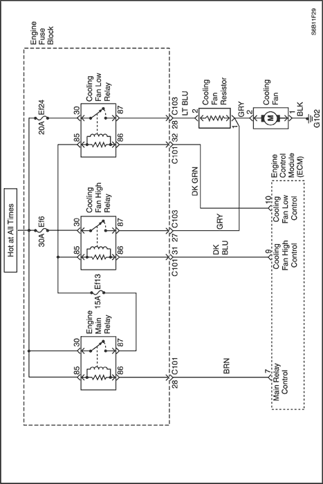
Circuit Description
Ignition voltage is supplied directly to the cooling fan relay coil. The engine control module(ECM) controls the relay by grounding the control circuit via an internal switch called a driver. The primary function of the driver is supply the ground for the component being controlled. Each driver has a fault line which is monitored by the ECM. When the ECM is commanding a component ON, the voltage of the control circuit should be low (near 0 volts). When the ECM is commanding the control circuit to a component OFF, the voltage potential of the circuit should be high(near battery voltage). If the fault detection circuit senses a voltage other than what is expected, the fault line status will change causing the DTC to set.
The relay is used to control the high current flow to the cooling fan motors. This allows the ECM driver to only have to handle the relatively low current used by the relay.
Conditions for Running the DTC
Conditions for Setting the DTC
- An open or a short to battery/ground condition in the cooling fan control circuit exists.
Action Taken When the DTC Sets
- The Malfunction Indicator Lamp (MIL) will illuminate.
- The ECM will record operating conditions at the time the diagnostic fails. The information will be stored in the freeze frame and failure records buffers.
- A history DTC is stored.
Conditions for Clearing the MIL/DTC
- The MIL will turn off at the end of 3 consecutive validation cycles in which the diagnostic runs without a fault.
- A history DTC will clear after 40 warm up cycles without a fault.
- DTC(s) can be cleared by using the scan tool.
Diagnostic Aids
Using Freeze Frame and/or failure records data may aid in locating an intermittent condition. If the DTC cannot be duplicated, the information included in the Freeze Frame and/or failure records data can be useful in determining how many miles since the DTC set. The fail counter and Pass Counter can also be used to determine how many ignition cycles the diagnostics reported a Freeze Frame conditions (rpm, load, vehicle speed, temperature, etc.) that .are noted. This will isolate when the DTC failed.
DTC P0480 - Low Speed Cooling Fan Relay Circuit Fault
DTC P0481 - High Speed Cooling Fan Relay Circuit Fault
| Step | Action | Value(s) | Yes | No |
| 1 | Perform the Diagnostic System Check. Is the system check complete? | - | Go to Step 2 | |
| 2 | - Turn the ignition switch to ON, with the engine OFF.
- Install a scan tool.
- Command the relay ON and OFF.
Does the relay turn ON and OFF when commanded? | - | Go to Step 3 | Go to Step 5 |
| 3 | - Turn the ignition switch to LOCK.
- Disconnect the engine control module (ECM) connector.
- With a fused jump wire, connect the relay terminal 85 and 30.
- Using a digital voltmeter(DVM), measure the current in the relay control circuit to ground for 2 minutes.
Does the amperage measure less than the specified value? | 0.75 amps | | Go to Step 4 |
| 4 | - Turn the ignition switch to LOCK.
- Disconnect the relay.
- Using a DVM, measure the resistance from the relay control circuit in the ECM harness connector to ground.
Does the DVM display infinite resistance? | - | Go to Step 12 | Go to Step 10 |
| 5 | - Turn the ignition switch to LOCK.
- Disconnect the relay.
- Connect a test light between the relay coil terminals 86 and 85 in the relay harness connector.
- Turn the ignition switch to ON.
- Using the scan tool, command the relay ON and OFF.
Does the test light turn ON and OFF with each commanded? | - | Go to Step 8 | Go to Step 6 |
| 6 | - With the test light connected to ground, probe the ignition feed circuit in the relay harness connector.
- Turn the ignition ON.
Does the test light illuminate? | - | Go to Step 7 | Go to Step 11 |
| 7 | - Turn the ignition switch to LOCK.
- Reconnect the relay.
- Disconnect the ECM connector containing the relay control circuit.
- With a fused jump wire, connect the relay terminal 85 and 30.
- With a fused jumper wire connected to ground, probe the relay control circuit in the ECM harness connector.
Does the relay operate? | - | Go to Step 9 | Go to Step 10 |
| 8 | Check the connections at the relay. Is a problem found and corrected? | - | Go to Step 14 | Go to Step 12 |
| 9 | Check the connection at the ECM. Is a problem found and corrected? | - | Go to Step 11 | Go to Step 13 |
| 10 | Repair the faulty relay control circuit. Is the repair complete? | - | Go to Step 14 | - |
| 11 | Repair the faulty relay ignition feed circuit. Is the repair complete? | - | Go to Step 14 | - |
| 12 | Replace the relay. Is the replacement complete? | - | Go to Step 14 | - |
| 13 | Replace the ECM. Is the replacement complete? | - | Go to Step 14 | - |
| 14 | - Using the scan tool, clear the Diagnostic Trouble Codes (DTCs).
- Start the engine and idle at normal operating temperature.
- Operate the vehicle within the conditions for setting the DTC as specifiec in the supporting text.
Does the scan tool indicate that this diagnostic ran and passed? | - | Go to Step 15 | Go to Step 2 |
| 15 | Check if any additional DTCs are set. Are any DTCs displayed that have not been diagnosed? | - | Go to applicable DTC table | System OK |
Diagnostic Trouble Code (DTC) P0501
Vehicle Speed No Signal (M/T Only)
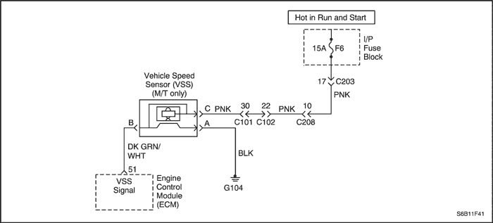
Circuit Description
Vehicle speed information is provided to the engine control module (ECM) by the vehicle speed sensor (VSS). The VSS is a permanent magnet generator that is mounted in the transaxle and produces a pulsing voltage whenever vehicle speed is over 3 mph (5km/h). The A/C voltage level and the number of pulses increase with vehicle speed. The ECM converts the pulsing voltage into mph (km/h) and then supplies the necessary signal to the instrument panel for speedometer/ odometer operation and to the cruise control module and multi-function alarm module operation. The Diagnostic Trouble Code (DTC) will detect if vehicle speed is reasonable according to engine rpm and load.
Conditions for Running the DTC
- Engine speed is greater than 2496rpm.
- Mass air flow is greater than 201mg/TDC.
Conditions for Setting the DTC
- No vehicle running condition detected for 25 seconds.
Action Taken When the DTC Sets
- The Malfunction Indicator Lamp (MIL) will illuminate.
- The ECM will record operating conditions at the time the diagnostic fails. This information will be stored in the Freeze Frame and Failure Records buffers.
- A history DTC is stored.
Conditions for Clearing the MIL/DTC
- The MIL will turn off at the end of a consecutive validation cycle in which the diagnostic runs without a fault.
- A history DTC will clear after 40 warm up cycles without a fault.
- Using the scan tool can clear DTC(s).
Diagnostic Aids
An Intermittent problem may be caused by a poor connection, rubbed through wire insulation, or wire that is broken inside the insulation.
VSS signal circuit should be thoroughly checked for the following conditions
- Backed-out terminals
- Improper mating
- Broken locks
- Improperly formed
- Damaged terminals
- Poor terminal to wire connection
- Physical damage to the wiring harness
Ensure the VSS is correctly torqued to the trnasaxle housing.
DTC P0501 - Vehicle Speed No Signal (M/T Only)
| Step | Action | Value(s) | Yes | No |
| 1 | Perform the Diagnostic System Check. Is the system check complete? | - | Go to Step 2 | |
| 2 | Notice : Running the vehicle in gear with the wheels hanging down at full travel will damage the drive axles. - Turn the ignition ON, with the engine OFF.
- Install a scan tool.
- Raise the drive wheels.
- Support the lower control arms so that the drive axles are in a horizontal (straight) position.
- Allow the engine to idle in gear.
Does the scan tool display vehicle speed above the specified value? | 0 mph | Go to Step 3 | Go to Step 4 |
| 3 | - Turn the ignition ON, with the engine OFF.
- Review the Freeze Frame data and note the parameters.
- Operate the vehicle within the Freeze Frame conditions and Conditions for Setting this DTC.
Does the scan tool display the vehicle speed above the specified value? | 0 mph | Go to Step 12 | Go to Step 4 |
| 4 | - Turn the ignition OFF.
- Disconnect the engine control module(ECM) connector.
- Using a digital voltmeter(DVM) connected to ground, measure the voltage in the Vehicle Speed Sensor (VSS) signal circuit, at terminal B while rotating the wheels.
Is the voltage greater than or eqaul to specified value? | 0.5V | Go to Step 12 | Go to Step 5 |
| 5 | Measure the resistance in the VSS signal circuit while rotating the wheels. Is the resistance greater than the specified value? | 1950Ω | Go to Step 6 | Go to Step 7 |
| 6 | Check the VSS signal circuit for an open and repair as necessary. Is the repair complete? | - | Go to Step 12 | Go to Step 9 |
| 7 | Is the resistance value within or equal to the specified value? | 1300-1950Ω | Go to Step 8 | Go to Step 9 |
| 8 | Check the VSS signal circuit for a short to ground or for being shorted together and repair as necessary. Is a repair necessary? | - | Go to Step 12 | Go to Step 12 |
| 9 | - Remove the VSS.
- Measure the resistance between terminals A and C.
Is the resistance value within the specified value? | 1300-1950Ω | Go to Step 11 | Go to Step 10 |
| 10 | Replace the VSS. Is the action complete? | - | Go to Step 12 | - |
| 11 | Replace the ECM. Is the action complete? | - | Go to Step 12 | - |
| 12 | - Using the scan tool, clear the Diagnostic Trouble Codes (DTCs).
- Start the engine and idle at normal operating temperature.
- Operate the vehicle within the conditions for setting the DTC as specifiec in the supporting text.
Does the scan tool indicate that this diagnostic ran and passed? | - | Go to Step 13 | Go to Step 2 |
| 13 | Check if any additional DTCs are set. Are any DTCs displayed that have not been diagnosed? | - | Go to applicable DTC table | System OK |
Diagnostic Trouble Code (DTC) P0510
Throttle Position Switch Circuit Fault
Circuit Description
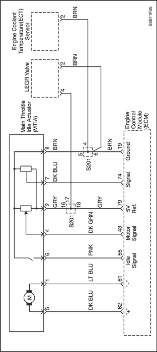
The aim of the MTIA(Main Throttle Idle Actuator) is to control the idle speed with the throttle body itself. The throttle is motorized for low opening angle (0°, 18°). The characteristics of the air flow are not the same for low and high opening angles. As a matter of fact, the gradient of the mass air flow function of TP sensor is lower for small angles that permits to be more precise during the idle speed control. Out of idle speed the throttle is actuated mechanically by a classical bowdencable.
This switch indicates throttle plate in idle position when contact closed. This switch is fixed at the DC-motor drive and the throttle plate closes the contact in dependence to the actual motor drive position.
Conditions for Running the DTC
(Throttle switch open)
- Ignition switch is ON.
- No MTC adaptation condition.
- No failure in TP sensor or MTIA.
(Throttle switch closed)
- Ignition switch is ON.
- No MTC adaptation condition.
- No failure in TP sensor.
- Throttle position is higher than 20.15° during 2 seconds.
Conditions for Setting the DTC
(Throttle switch open)
(Throttle switch closed)
Action Taken When the DTC Sets
- The Malfunction Indicator Lamp (MIL) will illuminate.
- The ECM will record operating conditions at the time the diagnostic fails. This information will be stored in the Freeze Frame and Failure Records buffers.
- A history DTC is stored.
Conditions for Clearing the MIL/DTC
- The MIL will turn off at the end of three consecutive validation cycles in which the diagnostic runs without a fault.
- A history DTC will clear after 40 warm up cycles without a fault.
- Using the scan tool can clear DTC(s).
Diagnostic Aids
An Intermittent problem may be caused by a poor connection, rubbed through wire insulation, or wire that is broken inside the insulation.
VSS signal circuit should be thoroughly checked for the following conditions
- Backed-out terminals
- Improper mating
- Broken locks
- Improperly formed
- Damaged terminals
- Poor terminal to wire connection
- Physical damage to the wiring harness
Ensure the VSS is correctly torqued to the trnasaxle housing.
DTC P0510 - Throttle Position Switch Circuit Fault
| Step | Action | Value(s) | Yes | No |
| 1 | Perform the Diagnostic System Check. Is the system check complete? | - | Go to Step 2 | |
| 2 | - Turn the ignition switch to LOCK.
- Disconnect the MTIA connector.
- Disconnect the ECM connector.
- Check for a short to ground or open in the wire between the MTIA connector terminal 4 and ECM connector terminal 43.
Is the problem found? | - | Go to Step 4 | Go to Step 3 |
| 3 | Check for a high voltage or open in the wire between the MTIA connector terminal 4 and ECM connector terminal 43. Is the problem found? | - | Go to Step 4 | Go to Step 5 |
| 4 | Repair the wire or the connector terminal as needed. Did you complete the repair? | - | Go to Step 7 | - |
| 5 | Replace the MTIA. Did you complete the replacement? | - | Go to Step 7 | - |
| 6 | Replace the ECM. Did you complete the replacement? | - | Go to Step 8 | - |
| 7 | - Using the scan tool, clear the Diagnostic Trouble Codes (DTCs).
- Start the engine and idle at normal operating temperature.
- Operate the vehicle within the conditions for setting the DTC as specifiec in the supporting text.
Does the scan tool indicate that this diagnostic ran and passed? | - | Go to Step 8 | Go to Step 2 |
| 8 | Check if any additional DTCs are set. Are any DTCs displayed that have not been diagnosed? | - | Go to applicable DTC table | System OK |
 | |  | |
| © Copyright Chevrolet Europe. All rights reserved |