MAINTENANCE AND REPAIR
ON-VEHICLE SERVICE


Fuel Tank
Removal Procedure
Caution : The fuel system is under pressure. To avoid fuel spillage and the risk of personal injury or fire, it is necessary to relieve the fuel system pressure before disconnecting the fuel lines.
- Relieve the fuel pressure. Refer to "Fuel Pump"in this section.
- Disconnect the negative battery cable.
- Drain the fuel tank.
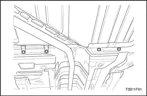
- Disconnect the parking brake cable retainer clampsand the support along the fuel tank to provide clearancefor the tank.
- Remove the fuel tank filler tube clamp at the fuel tank.
- Disconnect the fuel tank filler tube.
- Disconnect the fuel tank filler tube at the fuel tank.
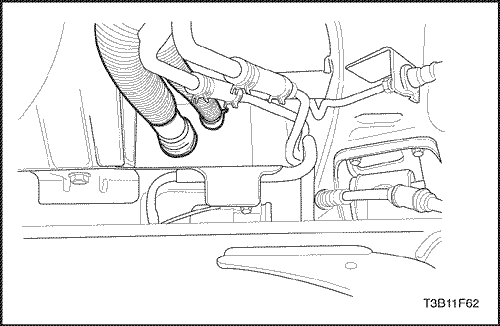
- Disconnect the canister vapor tube at control valvevapor tube.
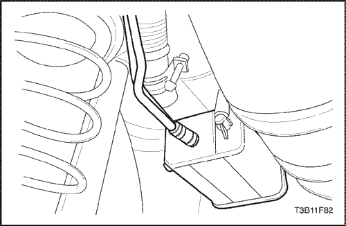
- Disconnect the fuel pump harness connector at theright rear corner of the fuel tank.
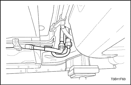
- Disconnect the fuel inlet line near the right front of the fuel tank.
- Disconnect the wiring harness clips and the fuel lineclips as needed.
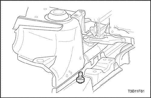
- Support the fuel tank.
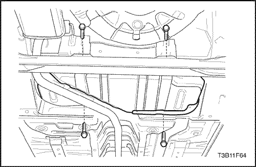
- Remove the fuel tank retaining bolts.
- Carefully lower the fuel tank.
- Remove the fuel tank.
- Transfer any parts as needed.
Installation Procedure
- Raise the fuel tank into position.
- Install the fuel tank mounting bolts.
Tighten
Tighten the fuel tank retaining bolts to 20 N•m(15 lb-ft).
- Connect the fuel outlet line.
- Connect the wiring harness clips and the fuel lineclips as needed.
- Connect the fuel pump electrical connector.
- Connect the fuel vapor line.
- Connect the fuel tank filler tube and fuel tank vent tube.
- Install the fuel tank filler tube clamp at the fuel tank.
- Install the parking brake cable retainer clamps andthe support.
Tighten
Tighten the parking brake cable retainer clamps to10 N•m (89 lb-in ).
- Connect the negative battery cable.
- Fill the fuel tank.
- Perform a leak check of the fuel tank and the fuelline connections.
Fuel Pump
Removal Procedure
Caution : The fuel system is under pressure. To avoid fuel spillage and the risk of personal injury or fire, it is necessary to relieve the fuel system pressure before disconnecting the fuel lines.
- Relieve the fuel system pressure.
- Remove the fuel cap.
- Remove fuel pump fuse EF10 from the engine fuse block.
- Start the engine and allow the engine to stall.
- Crank the engine for an additional the seconds.
- Disconnect the negative battery cable.
- Remove the rear seat Reter to Section 9H, Seats.
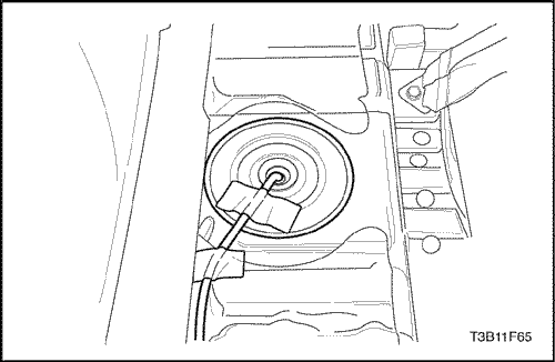
- Remove the fuel pump access cover.
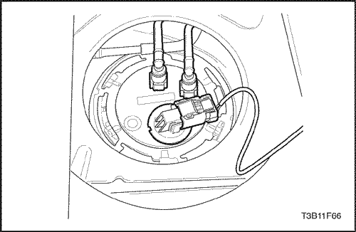
- Disconnect the electrical connector at the fuel pumpassembly.
- Disconnect the fuel outlet line.
- Turn the lock ring counterclockwise to clear the tanktabs.
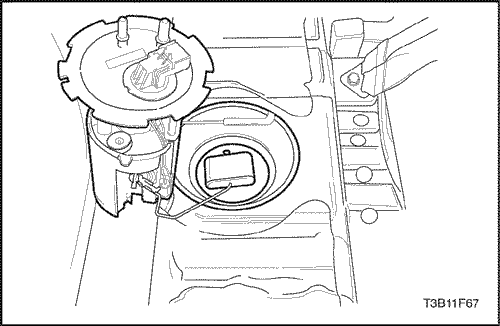
- Remove the fuel pump assembly from the tank.
- Remove and discard the gasket.
Installation Procedure
- Clean the gasket mating surface on the fuel tank.
- Position the new gasket in place.
- Install the fuel pump into the fuel tank in the same location as removed for ease of line and connector installation.
- Position the lock ring in place and turn it clockwise until it contacts the tank stop.
- Connect the fuel pump assembly connector.
- Install the fuel pump outlet line.
- Install the pump access cover.
- Connect the negative battery cable.
- Perform an operational check of the fuel pump.
- Install the rear seat. Refer to Section 9H, Seats.
Fuel Sender
Removal Procedure
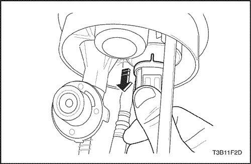
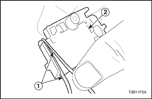
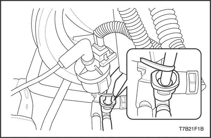
- Disconnect the insulator connector.
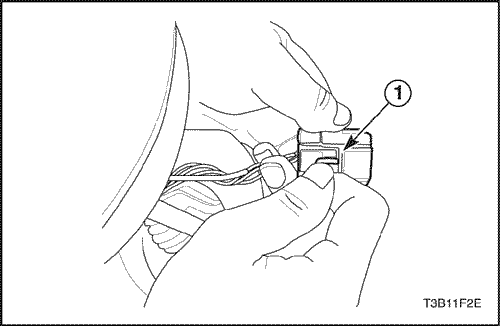
- Push the terminal wedge(1) in the insulator connector.
Notice : The wedge may be disconnected with severe load but can be reconnected.
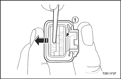
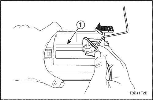
- Push the wedge(1) outside and then pull the wires to disconnect from insulator.
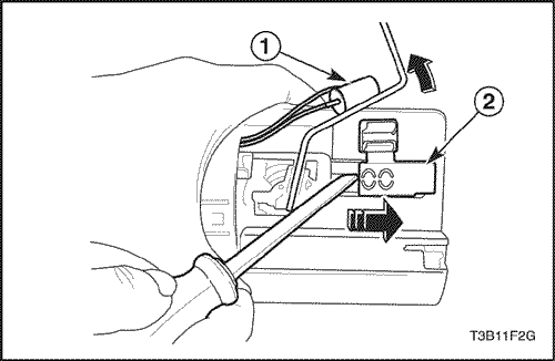
- Remove the fuel-level sensor(1) from the sender-housing(2).
- Remove the sender-housing(2).
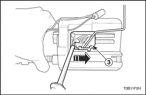
- Remove fuel sender assembly(3).
Installation Procedure
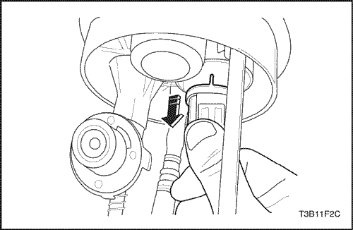
- Wind the wires(1) the sender assembly(2).
- Install the sender assembly onto the fuel pump assembly(1).
Notice : Unless correctly install the sender assmembly, fuel gauge indicate inexactly.
- Install the fuel-level sensor onto the sender-housing.
Notice : Unless correctly install the fuel-level sensor, fuel-level warning lamp indicate inexactly.
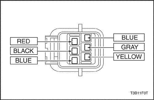
- Connect the wire into the insulator connector.
- Connect the insulator connector.
Fuel Filter
Removal Procedure
- Disconnect the negative battery cable.
Caution : The fuel system is under pressure. To avoid fuel spillage and the risk of personal injury or fire, it is necessary to relieve the fuel system pressure before disconnecting the fuel lines.
- Relieve the fuel system pressure. Refer to "Fuel Pump" in this section.
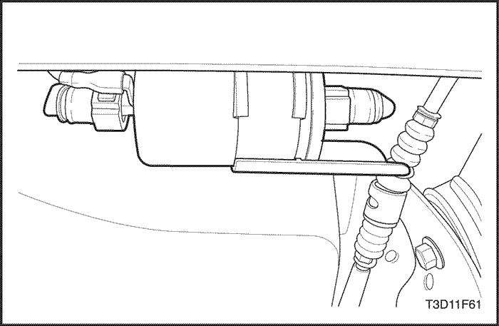
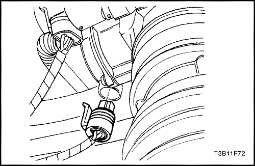
- Disconnect the inlet/outlet fuel lines by moving the line connector lock forward and pulling the hose off of the fuel filter tube.
- Disconnect the fuel filter ground.
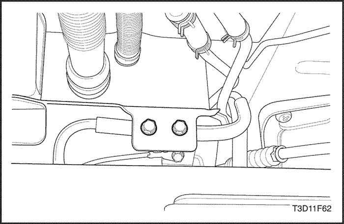
- Remove the fuel filter bracket bolts.
- Pull the fuel filter out of the retaining clamp.
Installation Procedure
- Install the new fuel filter into the retaining clamp. Note the flow direction.
- Install the fuel filter bracket bolts.
- Connect the inlet/outlet lines. Secure the lines with the connector lock.
- Perform a leak test of the fuel filter.
Fuel Rail and Injectors (1.2 SOHC)
Removal Procedure
Caution : The fuel system is under pressure. To avoid fuel spillage and the risk of personal injury or fire, it is necessary to relieve the fuel system pressure before disconnecting the fuel lines.
- Disconnect the negative battery cable.
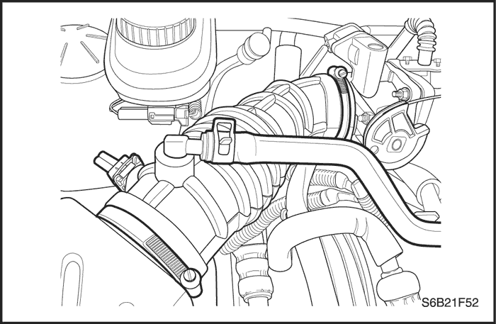
- Remove the throttle body. Refer to "Throttle Body (1.2 SOHC)" in this section.
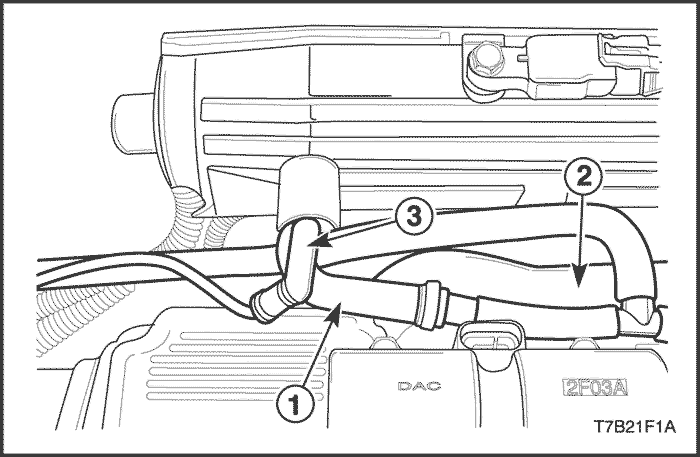
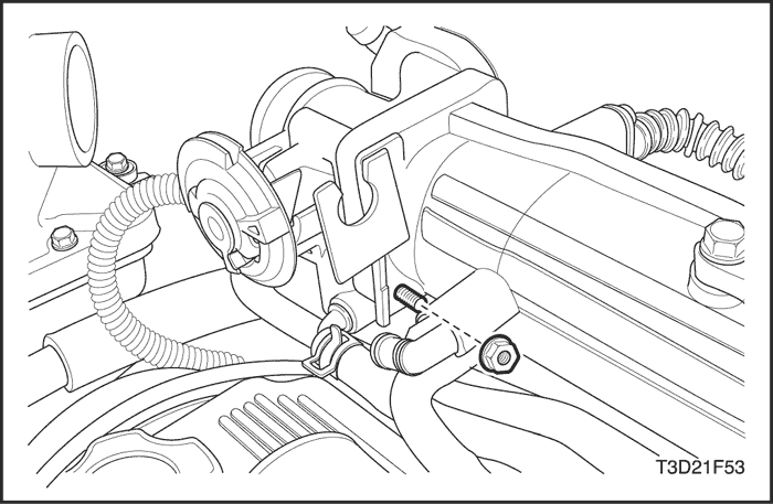
- Disconnect the PCV hose (1), coolant hose (2) and vacuum hose (3).
- Disconnect the fuel feed line from the fuel rail.
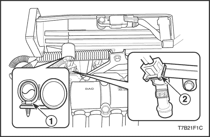
- Disconnect the wiring harness from the clip (1).
- Disconnect the fuel injector harness connector (2).
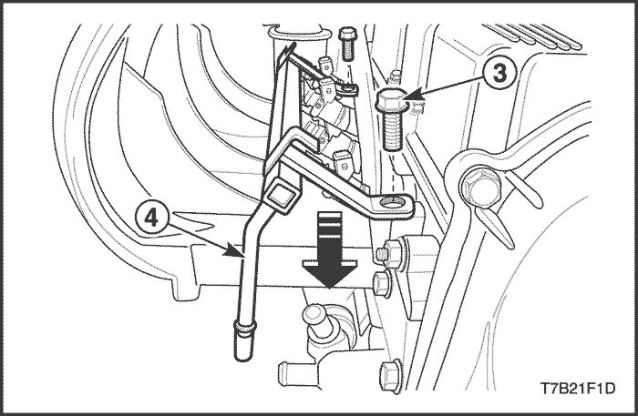
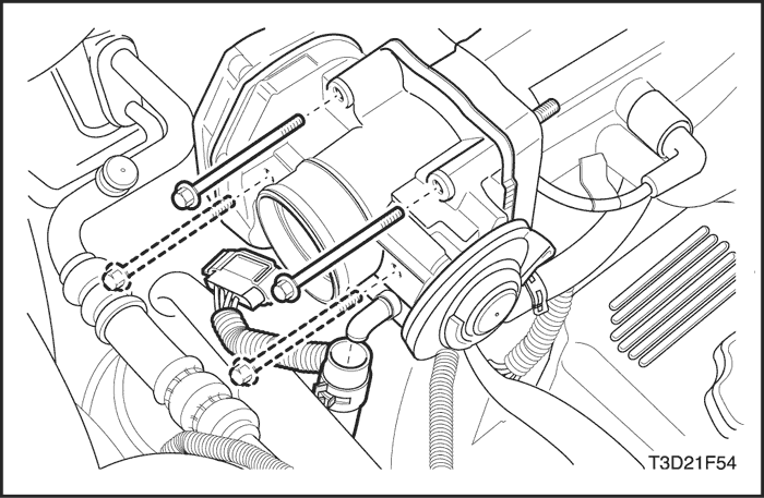
- Remove the fuel rail mounting bolts (3).
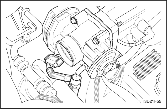
- Remove the fuel rail (4) with the fuel injectors attached.
Notice : Before removal, the fuel rail assembly may be cleaned with a spray-type cleaner, following package instructions. Do not immerse the fuel rails in liquid cleaning solvent. Use care in removing the fuel rail assembly to prevent damage to the electrical connectors and the injector spray tips. Prevent dirt and other contaminants from entering open lines and passages. Fittings should be capped and holes plugged during service.
Important : If an injector becomes separated from the rail and remains in the cylinder head, replace the injector O-ring seals and the retaining clip.
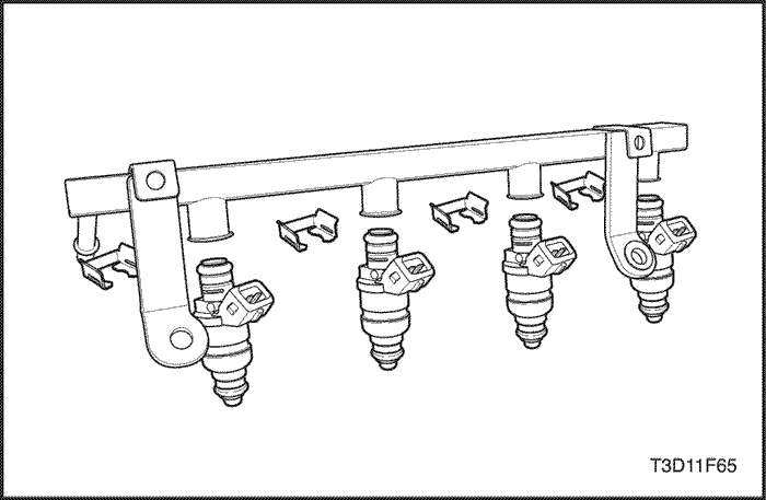
- Remove the fuel injector retainer clips.
- Remove the fuel injectors by pulling down and out.
- Discard the fuel injector O-rings.
Installation Procedure
Important : Different injectors are calibrated for different flow rates. When ordering new fuel injectors, be certain to order the identical part number that is inscribed on the old injector.
- Lubricate the new fuel injector O-rings with engine oil. Install the new O-rings on the fuel injectors.
- Install the fuel injectors into the fuel rail sockets with the fuel injector terminals facing outward.
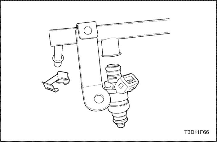
- Install the fuel injector retainer clips onto the fuel injectors and the fuel rail ledge.
- Make sure that the clip is parallel to the fuel injector harness connector.
- Install the fuel rail assembly into the cylinder head.
- Install the fuel rail mounting bolts.
Tighten
Tighten the fuel rail mounting bolts to 25 N•m (18 lb-ft).
- Connect the fuel feed line.
- Connect the fuel injector harness connectors. Rotate each fuel injector as required to avoid stretching the wiring harness.
- Connect the negative battery cable.
- Perform a leak check of the fuel rail and fuel injectors.
Fuel Rail and Injectors (1.4 DOHC)
Removal Procedure
Caution : The fuel system is under pressure. To avoid fuel spillage and the risk of personal injury or fire, it is necessary to relieve the fuel system pressure before disconnecting the fuel lines.
- Relieve the fuel system pressure. Refer to "Fuel Pump"in this section.
- Disconnect the negative battery cable.
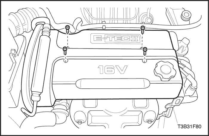
- Remove the engine beautification cover bolts.
- Remove the engine beautification cover.
- Disconnect the throttle position sensor connector.
- Disconnect the idle air control valve connector.
- Disconnect intake air temperature sensor connector.
- Disconnect the camshaft position sensor connector.
- Disconnect the manifold absolute pressure sensor connector.
- Disconnect the fuel injector harness connectors.
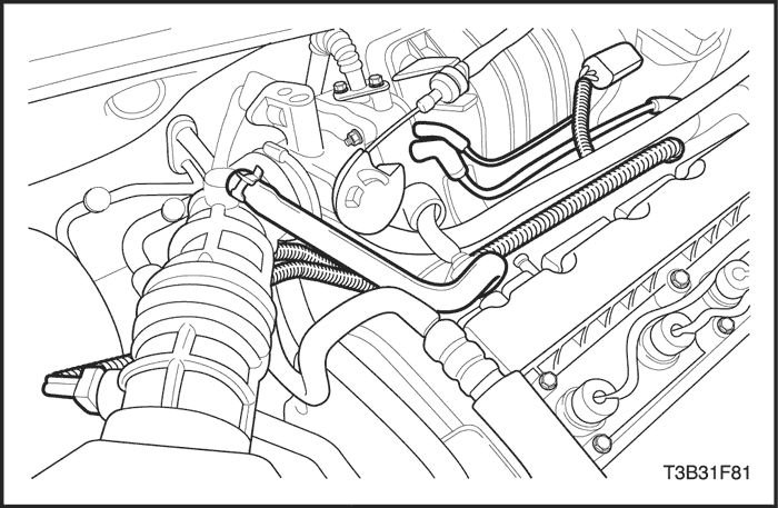
- Remove the purge solenoid valve-to-intake manifold hose.
- Remove the manifold absolute pressure sensor vacuum hose.
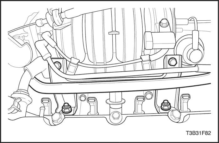
- Remove the intake manifold upper bracket bolts.
- Remove the intake manifold upper bracket.
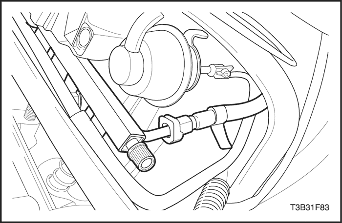
- Disconnect the fuel feeding line.
- Disconnect the throttle body outlet coolant hose.
- Remove the fuel rail mounting bolts.
Notice : Before removal, the fuel rail assembly may be cleaned with a spray-type cleaner, following package instructions. Do not immerse the fuel rails in liquid cleaning solvent. Use care in removing the fuel rail assembly to prevent damage to the electrical connectors and the injector spray tips. Prevent dirt and other contaminants from entering open lines and passages. Fittings should be capped and holes plugged during service.
Important : If an injector becomes separated from the rail and remains in the cylinder head, replace the injector O-ring seals and the retaining clip.
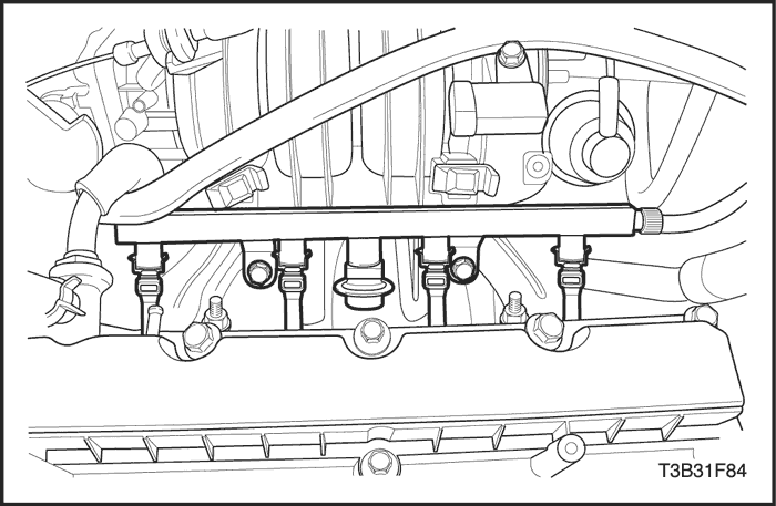
- Remove the fuel rail with the fuel injectors attached.
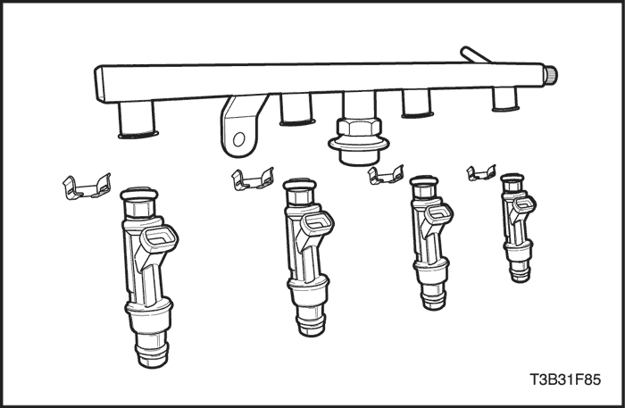
- Remove the fuel injector retainer clips.
- Remove the fuel injectors by pulling down and out.
- Discard the fuel injector O-rings.
Installation Procedure
Important : Different injectors are calibrated for different flow rates. When ordering new fuel injectors, be certain to order the identical part number that is inscribed on the old injector.
- Lubricate the new fuel injector O-rings with engine oil. Install the new O-rings on the fuel injectors.
- Install the fuel injectors into the fuel rail sockets with the fuel injector terminals facing outward.
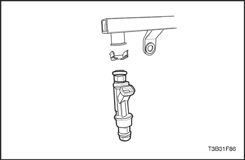
- Install the fuel injector retainer clips onto the fuel injectors and the fuel rail ledge.
- Make sure that the clip is parallel to the fuel injector harness connector.
- Install the fuel rail assembly into the cylinder head.
- Install the fuel rail mounting bolts.
Tighten
Tighten the fuel rail mounting bolts to 25 N•m (18 lb-ft).
- Connect the throttle body outlet coolant hose.
- Connect the fuel feeding line.
- Install the intake manifold upper bracket.
- Install the intake manifold upper bracket bolts.
- Install the manifold absolute pressure sensor vacuum hose.
- Install the purge solenoid valve-to-intake manifold hose.
- Connect the fuel injector harness connectors.
- Connect the manifold absolute pressure sensor connector.
- Connect the camshaft position sensor connector.
- Connect the intake air temperature sensor connector.
- Connect the idle air control valve connector.
- Connect the throttle position sensor connector.
- Install the engine beautification cover.
- Install the engine beautification cover bolts.
- Connect the negative battery cable.
- Perform a leak check of the fuel rail and fuel injectors.
Engine Coolant Temperature (ECT) Sensor (1.2 SOHC)
Removal Procedure
- Relieve the coolant system pressure.
- Disconnect the negative battery cable.
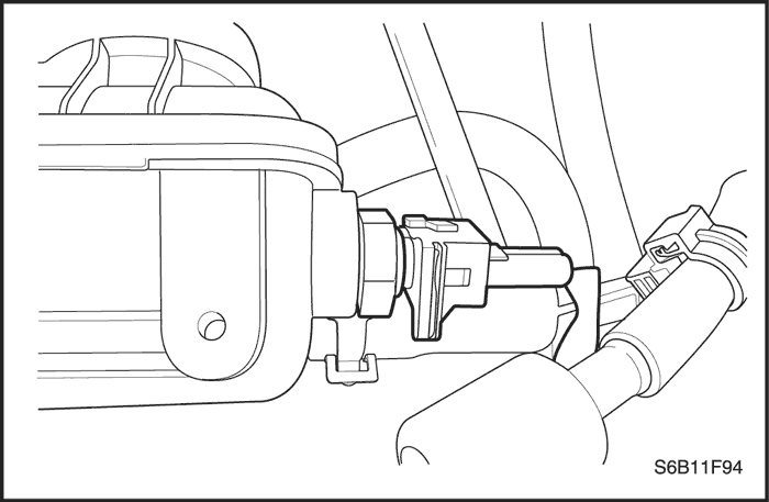
- Disconnect the engine coolant temperature (ECT) sensor connector.
Notice : Use care when handling the ECT sensor. Damage to the sensor will affect the proper operation of the fuel injection system.
- Carefully remove the ECT sensor from the coolant outlet case.
Installation Procedure
- Coat the threads on the ECT sensor with sealer.
Notice : Use care when handling the ECT sensor. Damage to the sensor will affect the proper operation of the fuel injection system.
- Install the ECT sensor into the coolant outlet case.
Tighten
Tighten the engine coolant temperature sensor to 20 N•m (15 lb-ft).
- Connect the ECT sensor connector.
- Fill the cooling system.
- Connect the negative battery cable.
Engine Coolant Temperature (ECT) Sensor (1.4 DOHC)
Removal Procedure
- Relieve the coolant system pressure.
- Disconnect the negative battery cable.
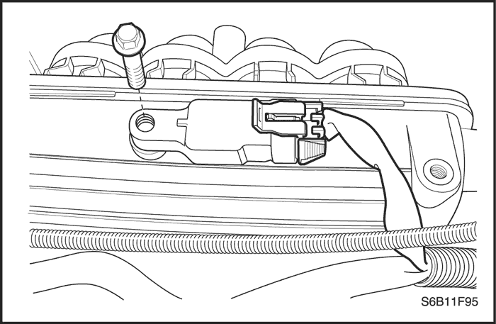
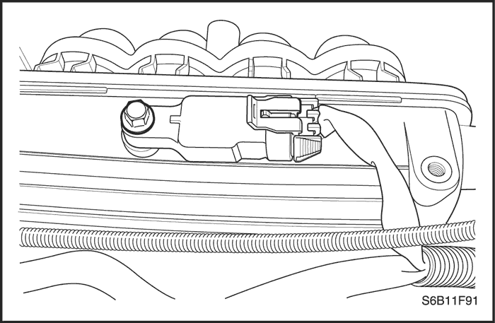
- Disconnect the coolant temperature (ECT)sensor connector.
Notice : Use care when handling the ECT sensor. Damage to the sensor will affect the proper operation of the fuel injection system.
- Carefully remove the ECT sensor from the cylinderhead underneath the electronic ignition (EI) system ignition coil.
Installation Procedure
- Coat the threads on the ECT sensor with sealer.
Notice : Use care when handling the ECT sensor. Damage to the sensor will affect the proper operation of the fuel injection system.
- Install the ECT into the cylinder head.
Tighten
Tighten the coolant temperature sensor to20 N•m (15 lb-ft).
- Connect the ECT sensor connector.
- Fill the cooling system.
- Connect the negative battery cable.
Idle Air Control Valve (1.4 DOHC)
Removal Procedure
- Disconnect the negative battery cable.
- Disconnect the idle air control (IAC) valve connector.
- Remove the IAC valve retaining bolts.
Notice : On IAC valves that have been in service, do notpush on the valve pintle. The force required to move thepintle may damage the threads on the worm drive.
- Remove the IAC valve.
- Clean the IAC valve O-ring seal area, the pintle valveseat and the air passage with a suitable fuel systemcleaner. Do not use methyl ethyl ketone.
Installation Procedure
Important : If installing a new IAC valve, be sure to replaceit with an identical part. The IAC valve pintle shapeand diameter are designed for the specific application.Measure the distance between the tip of the IAC valvepintle and the mounting flange. If the distance is greaterthan 28 mm, use finger pressure to slowly retract thepintle.
The force required to retract the pintle will notdamage the IAC valve.The purpose of the 28 mm settingis to prevent the IAC pintle from bottoming out onthe pintle seat. This 28 mm setting is also an adequatesetting for controlled idle on a restart.
- Lubricate a new O-ring with engine oil. Install the newO-ring onto the valve.
- Install the IAC valve into the throttle body.
- Install the IAC valve retaining bolts.
Tighten
Tighten the idle air control valve retaining bolts to3 N•m (27 lb-in).
- Connect the IAC valve connector.
- Connect the negative battery cable.
- Start the engine and check for the proper idle speed.
Throttle Position Sensor (1.4 DOHC)
Removal Procedure
- Disconnect the negative battery cable.
- Disconnect the throttle position (TP) sensor connector.
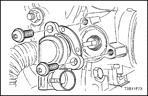
- Remove the TP sensor retaining bolts and the TPsensor.
Installation Procedure
- With the throttle valve closed, position the TP sensoron the throttle shaft. Align the TP sensor with the boltholes.
- Install the TP sensor retaining bolts.
Tighten
Tighten the throttle position sensor retaining bolts to2 N•m (18 lb-in).
- Connect the TP sensor connector.
- Connect the negative battery cable.
Throttle Body (1.2 SOHC)
Removal Procedure
- Disconnect the negative battery cable.
- Disconnect the PCV hose.
- Release the clamp bolts from the air outlet hose.
- Remove the Air Outlet hose.
- Disconnect the throttle cable from the mounting bracket.
- Disconnect the throttle cable by opening the throttle and moving the cable through the release slot.
- Remove the retaining nuts from the throttle cable bracket.
- Disconnect the throttle body electrical connector.
- Disconnect the coolant water hoses.
- Remove the throttle body retaining bolts.
Installation Procedure
Notice : Use care in cleaning old gasket material from machined aluminum surfaces. Sharp tools may damage sealing surfaces.
- Clean the gasket mating surface on the intake manifold.
Notice : The throttle body may be cleaned following disassemblyin a cold immersion-type cleaner. The throttleposition sensor and the idle air control valve should notcome in contact with any solvent or cleaner as they maybe damaged.
- Clean the throttle body.
- Install the throttle body assembly with a new gasket to the intake manifold.
- Install the throttle body retaining bolts.
Tighten
Tighten the throttle body retaining bolts to 10.3 N•m (91 lb-in).
- Install the coolant water hoses.
- Connect the throttle body electrical connector.
Important : Make sure the throttle control cables do nothold the throttle open. With the engine OFF, check tosee that the accelerator pedal is free.
- Connect the throttle cable.
- Connect the PCV hose.
- Connect the air outlet hose.
- Tighten the clamp bolts.
- Connect the negative battery cable.
Throttle Body (1.4 DOHC)
Removal Procedure
- Disconnect the negative battery cable.
- Disconnect the intake air temperature sensor connector.
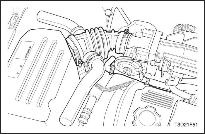
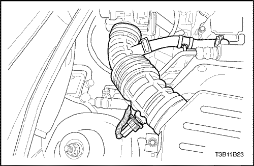
- Disconnect the breather tube from the air intake tube.
- Remove the air intake tube from the throttle body.
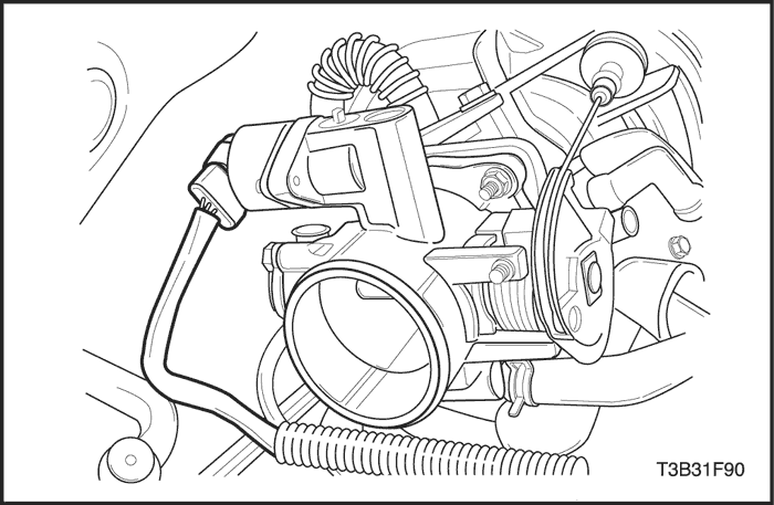
- Disconnect the throttle cables by opening the throttle and moving the cable through the release slot.
- Disconnect the throttle position (TP) sensor and the idle air control valve connectors.
- Remove the coolant hoses from the throttle body.
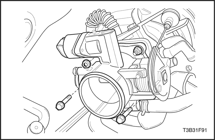
- Remove the throttle body retaining bolts.
- Remove the throttle body and discard the gasket.
- Remove the TP sensor. Refer to "Throttle Position Sensor"in this section.
- Remove the idle air control (IAC) valve. Refer to "Idle Air Control Valve"in this section.
Installation Procedure
Notice : Use care in cleaning old gasket material frommachined aluminum surfaces. Sharp tools may damagesealing surfaces.
- Clean the gasket mating surface on the intake manifold.
Notice : The throttle body may be cleaned following disassemblyin a cold immersion-type cleaner. The throttleposition sensor and the idle air control valve should notcome in contact with any solvent or cleaner as they maybe damaged.
- Clean the throttle body.
- Install the TP sensor. Refer to "Throttle Position Sensor" in this section.
- Install the IAC valve. Refer to "Idle Air Control Valve" in this section.
- Install the throttle body assembly with a new gasketto the intake manifold.
- Install the throttle body retaining bolts.
Tighten
Tighten the throttle body retaining bolts to 15 N•m(11 lb-ft).
- Install the coolant hoses.
Important : Make sure the throttle control cables do nothold the throttle open. With the engine OFF, check tosee that the accelerator pedal is free.
- Connect the throttle cables.
- Install the air intake tube.
- Connect the TP sensor connector and the IAC valveconnector.
- Connect the negative battery cable.
- Fill the cooling system.
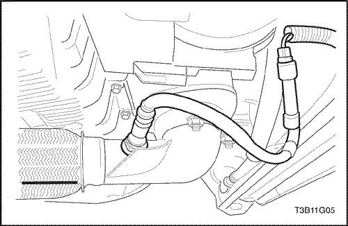
Front Heated Oxygen Sensor (HO2S1) (Typical)
Removal Procedure
- Disconnect the negative battery cable.
Notice : The oxygen sensor uses a permanently attached pigtail and connector. This pigtail should not be removed from the oxygen sensor. Damage or removal of the pigtail or the connector could affect proper operation of the oxygen sensor. Take care when handling the oxygen sensor. Do not drop the oxygen sensor.
- Disconnect the front heated oxygen sensor (HO2S1) connector.
Caution : Allow the engine to cool before removing the oxygen sensor. Removal of the oxygen sensor when the engine is hot may damage the threads in the exhaust manifold.
- Carefully remove the HO2S1 by using the oxygen sensor remover/installer DW 170-010 from the exhaust manifold.
Installation Procedure
Important : A special anti-seize compound is used onthe oxygen sensor threads. This compound consists ofa liquid graphite and glass beads. The graphite will burnaway, but the glass beads will remain, making the sensoreasier to remove. New or service sensors will alreadyhave the compound applied to the threads. If asensor is removed from any engine and if for any reasonit is to be reinstalled, the threads must have anti-seizecompound applied before reinstallation.
- Coat the threads of the HO2S1 with an anti-seize compound,if needed.
- Install the HO2S1 into the exhaust manifold.
Tighten
Tighten the oxygen sensor to 42 N•m (31 lb-ft).
- Connect the HO2S1 connector.
- Connect the negative battery cable.
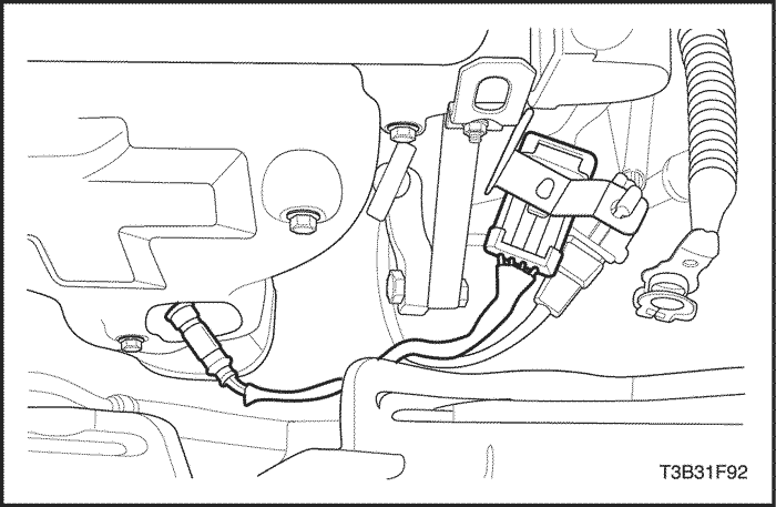
Rear Heated Oxygen Sensor (HO2S2) (Typical)
Removal Procedure
- Disconnect the negative battery cable.
Notice : The oxygen sensor uses a permanently attached pigtail and connector. This pigtail should not be removed from the oxygen sensor. Damage or removal of the pigtail or the connector could affect proper operation of the oxygen sensor. Take care when handling the oxygen sensor. Do not drop the oxygen sensor.
- Disconnect the electrical connector.
Caution : Allow the engine to cool before removing the oxygen sensor. Removal of the oxygen sensor when the engine is hot may damage the threads in the exhaust manifold.
- Carefully remove the HO2S2 by using the oxygen sensor remover/installer DW 170-010.
Installation Procedure
Important : A special anti-seize compound is used onthe oxygen sensor threads. This compound consists ofa liquid graphite and glass beads. The graphite will burnaway, but the glass beads will remain, making the sensoreasier to remove. New or service sensors will alreadyhave the compound applied to the threads. If asensor is removed from any engine and if for any reasonit is to be reinstalled, the threads must have anti-seizecompound applied before reinstallation.
- Coat the threads of the HO2S1 with an anti-seize compound,if needed.
- Install the HO2S2 into the exhaust front pipe.
Tighten
Tighten the oxygen sensor to 42 N•m (31 lb-ft).
- Connect the HO2S2 connector.
- Connect the negative battery cable.
Intake Air Temperature Sensor (1.2 SOHC)
Removal Procedure
- Disconnect the negative battery cable.
- Disconnect the intake air temperature (IAT) sensor connector.
- Remove the IAT sensor.
Installation Procedure
- Install the IAT sensor.
Tighten
Tighten the IAT sensor to 25 N•m (18 lb-ft).
- Connect the IAT connector.
- Connect the negative battery cable.
Intake Air Temperature Sensor (1.4 DOHC)
Removal Procedure
- Disconnect the negative battery cable.
- Disconnect the intake air temperature (IAT) sensorconnector.
- Remove the IAT sensor by pulling it out of the air intaketube.
Installation Procedure
- Insert the IAT sensor into the air intake tube.
- Connect the IAT connector.
- Connect the negative battery cable.
Manifold Absolute Pressure Sensor (1.2 SOHC)
Removal Procedure
- Disconnect the MAP sensor connector.
- Remove the bolt with the MAP sensor.
Installation Procedure
- Install the MAP sensor with the bolt.
Tighten
Tighten the MAP sensor bolt to 10 N•m (89 lb-in).
- Connect the MAP sensor connector.
- Connect the negative battery cable.
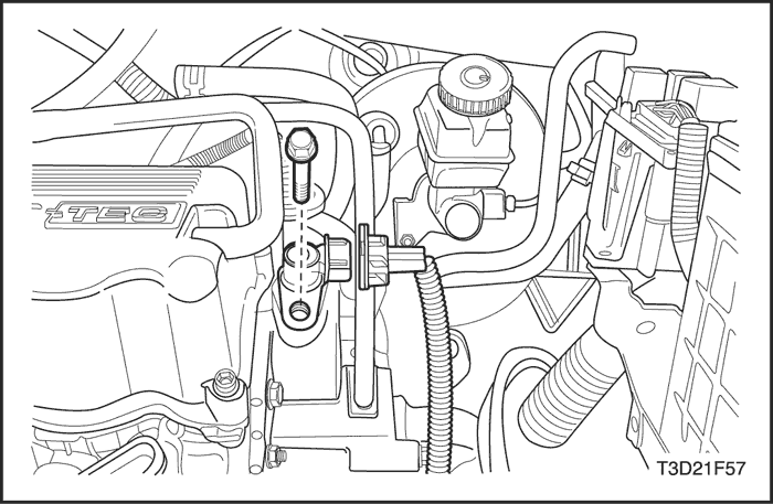
Manifold Absolute Pressure Sensor (1.4 DOHC)
Removal Procedure
- Disconnect the negative battery cable.
- Diseconnect the MAP Sensor connector.
- Remove the bolt with the MAP sensor.
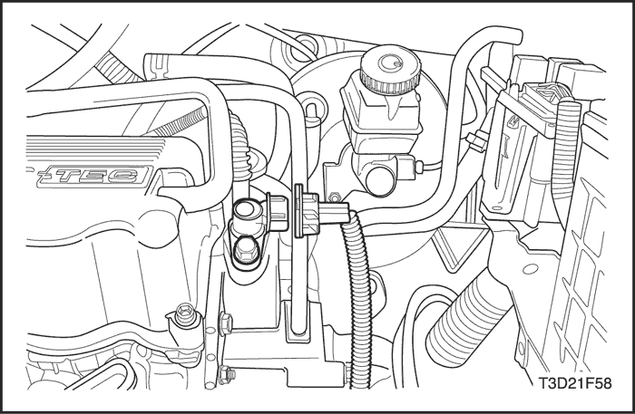
Installation Procedure
- Install the MAP sensor with the bolt.
Tighten
Tighten the MAP sensor bolt to 10 N•m (89 lb-in).
- Connect the MAP sensor connector.
- Connect the negative battery cable.
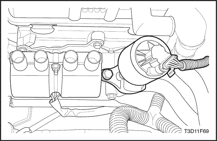
Exhaust Gas Recirculation Valve (1.2 SOHC)
Removal Procedure
- Disconnect the negative battery cable.
- Disconnect the EGR valve electrical connector.
- Remove the nuts and the EGR valve.
Installation Procedure
- Clean the mating surface.
- Install a new EGR valve gasket.
- Install the EGR valve with the retaining nuts.
Tighten
Tighten the exhaust gas recirculation valve retaining nuts to 30 N•m (22 lb-ft).
- Connect the EGR valve electrical connector.
- Connect the negative battery cable.
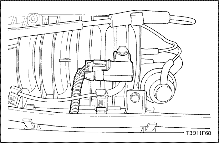
Exhaust Gas Recirculation Valve (1.4 DOHC)
Removal Procedure
- Disconnect the negative battery cable.
- Disconnect the EGR valve electrical connector.
- Remove the bolts and the EGR valve.
Installation Procedure
- Clean the cylinder head mating surface.
- Install a new EGR valve gasket.
- Install the EGR valve with the retaining bolts.
Tighten
Tighten the exhaust gas recirculation valve retaining bolts to 30 N•m (22 lb-ft).
- Connect the EGR valve electrical connector.
- Connect the negative battery cable.
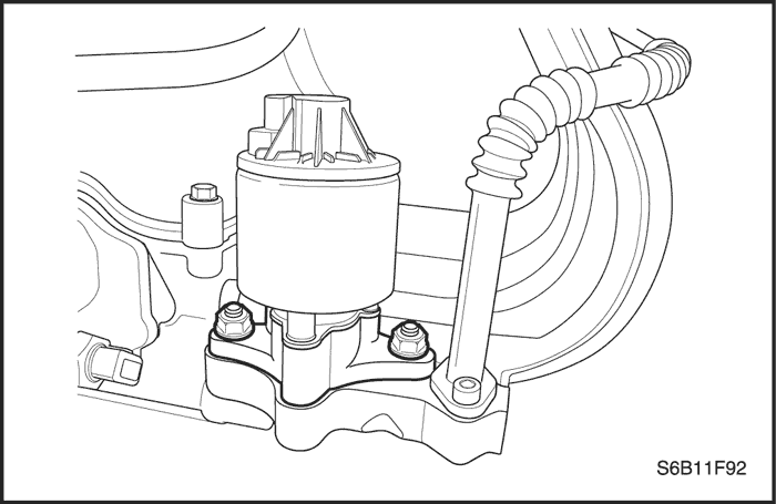
Knock Sensor
Removal Procedure
- Disconnect the negative battery cable.
- Remove the intake manifold. Refer to Section 1B, SOHC Engine Mechanical or Section 1C, DOHC Engine Mechanical.
- Disconnect the electrical connector at the knock sensor.
- Remove the knock sensor.
Installation Procedure
- Install the knock sensor.
Tighten
Tighten the knock sensor bolt to 20 N•m (15 lb-ft).
- Connect the electrical connector at the knock sensor.
- Install the intake manifold. Refer to Section 1B, SOHC Engine Mechanical.or Section 1C, DOHC Engine Mechanical.
- Connect the negative battery cable.
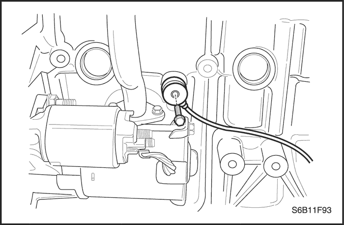
G Sensor
Removal Procedure
- Disconnect the negative battery cable.
- Disconnect the G sensor electrical connector and remove the G sensor.
Installation Procedure
- Install the G sensor and connect the electrical connector.
Tighten
Tighten the G sensor to 17 N•m (12.5 lb-ft).
- Connect the negative battery cable.
Evaporative Emission Canister
Removal Procedure
Caution : Canister and vacuum hoses contain fuel vapors. Do not smoke in the area or permit an open flame.
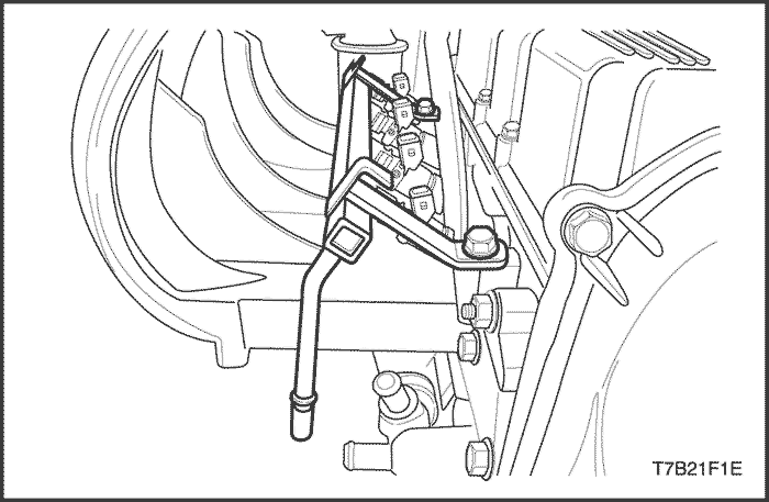
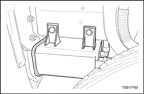
- Disconnect the evaporative (EVAP) emission canister fuel vapor hoses.
- Remove the bolt securing the EVAP emission canister flange to the vehicle.
- Slide the EVAP emission canister out of the track holder.
- Remove the EVAP emission canister.
Installation Procedure
- Insert the EVAP emission canister into the track and slide it into position.
- Install the EVAP emission canister flange bolt.
Tighten
Tighten the evaporative emission canister flange bolt to 20 N•m (15 lb-ft).
- Connect the canister fuel vapor hoses.
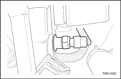
Crankshaft Position Sensor (1.2 SOHC)
Removal Procedure
- Disconnect the negative battery cable.
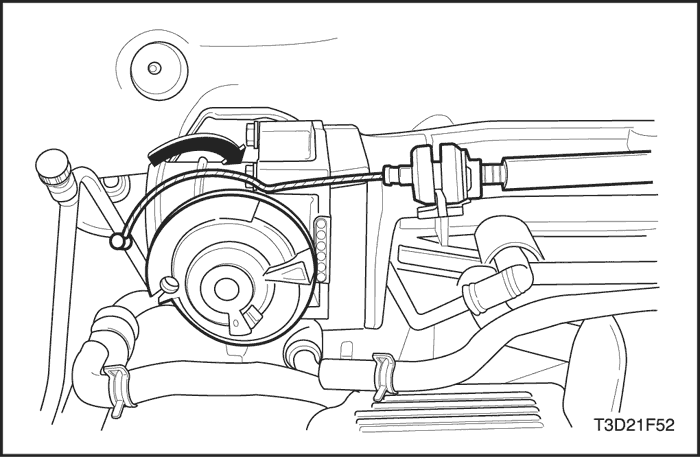
- Remove the air cleaner assembly.
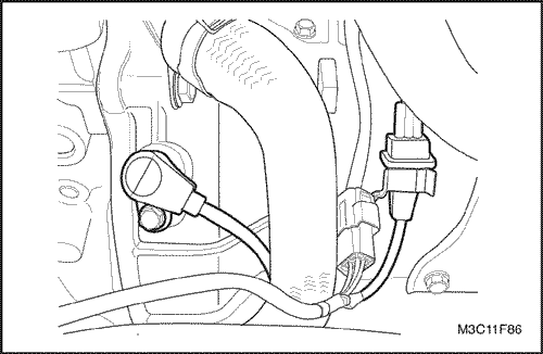
- Disconnect the crankshaft position (CKP) sensor connector.
- Remove the CKP sensor retaining bolt.
Installation Procedure
- Install the CKP sensor.
- Tighten the CKP sensor retaining bolt to 6.5 N•m (58 lb-in).
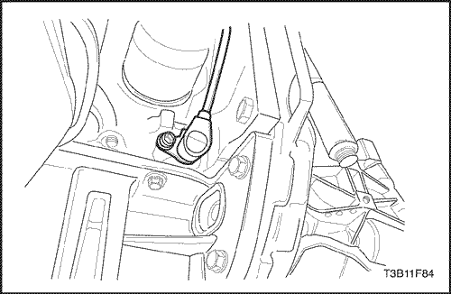
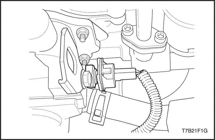
Crankshaft Position Sensor (1.4 DOHC)
Removal Procedure
- Disconnect the negative battery cable.
- Disconnect the crankshaft position (CKP) sensor connector at the frame bracket.
- Remove the wiring tie straps as needed.
- Remove the CKP sensor retaining bolt.
- Remove the CKP sensor.
Installation Procedure
- Install the CKP sensor with the retaining bolt.
Tighten
Tighten the crankshaft position sensor retaining bolt to 6.5 N•m (58 lb-in).
- Connect the CKP sensor connector at the frame bracket.
- Secure the wire with the tie straps as needed.
- Connect the negative battery cable.
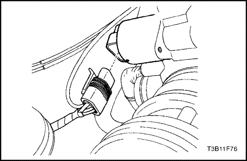
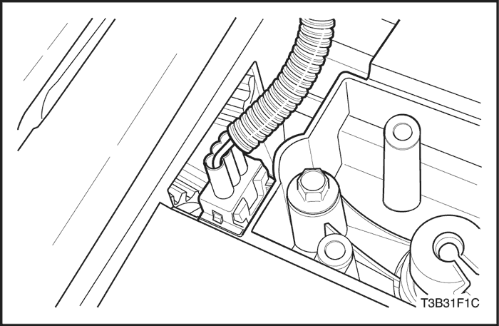
Camshaft Position Sensor (1.2 SOHC)
Removal Procedure
- Disconnect the negative battery cable.
- Disconnect the sensor electrical connector.
- Remove the camshaft position (CMP) sensor bolt and sensor.
Installation Procedure
- Install the CMP sensor and bolts.
Tighten
Tighten the camshaft position bolts to 12 N•m (106 lb-in).
- Connect the sensor electrical connector.
- Connect the negative battery cable.
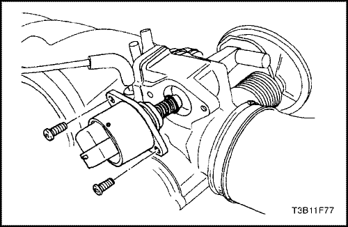
Camshaft Position Sensor (1.4 DOHC)
Removal Procedure
- Disconnect the negative battery cable.
- Disconnect the sensor electrical connector.
- Remove the front timing belt upper cover. Refer to Section 1C, DOHC Engine Mechanical.
- Remove the camshaft position (CMP) sensor bolts and sensor.
Installation Procedure
- Install the CMP sensor and bolts.
Tighten
Tighten the camshaft position bolts to 12 N•m (106 lb-in).
- Install the front timing belt upper cover. Refer to Section 1C, DOHC Engine Mechanical.
- Connect the sensor electrical connector.
- Connect the negative battery cable.
Engine Control Module (1.2 SOHC)
Removal Procedure
- Disconnect the negative battery cable.
- Disconnect the engine control module (ECM) connectors.
- Remove the ECM retaining bolts and nuts.
- Remove the ECM.
Installation Procedure
- Position the ECM in place.
- Install the ECM to the ECM mount and install the retaining bolts.
Tighten
Tighten the ECM retaining bolts to 5 N•m (44 lb-in).
- Connect the negative battery cable.
- Perform a crankshaft position system variation learning procedure.
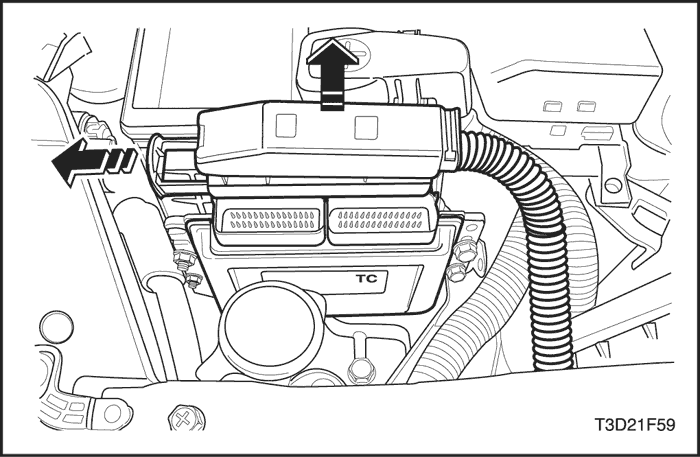
Engine Control Module (1.4 DOHC)
Removal Procedure
- Disconnect the negative battery cable.
- Disconnect the engine control module (ECM) connectors.
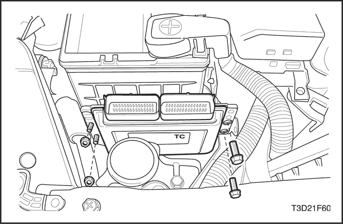
- Remove the ECM retaining bolts.
- Remove the ECM from the ECM mount.
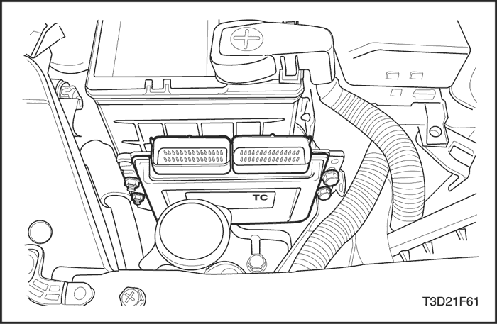
Installation Procedure
- Position the ECM in place.
- Install the ECM to the ECM mount and install the retaining bolts.
Tighten
Tighten the ECM retaining bolts to 4 N•m (35 lb-in).
- Connect the negative battery cable.
- Perform a crankshaft position system variation learning procedure. Refer to "TEC Learn Procedure" in this section.
| © Copyright Chevrolet Europe. All rights reserved |


