Diagnostic Trouble Code (DTC) P0171
Fuel Trim System lean
System Description
To provide the best possible combination of driveability, fuel economy, and emission control, a Closed Loop air/fuel metering system is used. While in Closed Loop, the Engine Control Module (ECM) monitors the Front Heated Oxygen Sensor (HO2S1) signal voltage and adjusts fuel delivery based on signal voltage. A change made to fuel delivery will be indicated by the long and short term fuel trim values which can be monitored with the scan tool. Ideal fuel trim values are around 128 (0%). If the HO2S1 signal is indicating a lean condition, the ECM will add fuel resulting in fuel trim values above 128 (0% to 100%). If a rich condition is detected, the fuel trim values will be below 128 (0% to -100%), indicating that the ECM is reducing the amount of fuel delivered. If exhaust emissions reach an excessive level due to a lean or rich condition, a fuel trim Diagnostic Trouble Code (DTC) is set.
Conditions for Setting the DTC
- The average of short term fuel trim value is greater than or equal to 0.94.
- No intrusive tests active.
- DTCs P0106, P0107, P0108, P0112, P0113, P0117, P0118, P0122, P0123, P0131, P0132, P0133, P0134, P0135, P1167, P1171, P0300, P0336, P0337, P0341, P0342, P0402, P0404, P1404, P0405, P0406, P0443, P0506, and P0507 are not set.
- Throttle Position (TP) is less than 80%.
- Engine speed is between 700 and 6000 rpm.
- Barometric Pressure (BARO) is greater than 72.0 kPa (10.4 psi).
- Coolant temperature is between 70 °C(158 °F) and 105 °C(221 °F).
- Manifold Absolute Pressure (MAP) is between 25 kPa (3.6 psi) and 90.0 kPa (13.1 psi).
- Intake Air Temperature (IAT) is between -10°C (14°F) and 90°C (194°F).
- Airflow is between 1.5 and 45 g/sec.
- Vehicle speed is less than 140 km/h (87 mph).
- System is in closed loop.
- Adaptive index is ready.
- System voltage is greater than 11 volts.
Action Taken When the DTC Sets
- The Malfunction Indicator Lamp (MIL) will illuminate after two consecutive ignitions cycle in which the diagnostic runs with the fault active (SOHC).
- The Malfunction Indicator Lamp (MIL) will illuminate after first consecutive ignitions cycle (DOHC).
- The ECM will record operating conditions at the time the diagnostic fails. This information will be stored in the Freeze Frame and Failure Records buffers.
- A history DTC is stored.
Conditions for Clearing the MIL/DTC
- The MIL will turn off after two consecutive ignition cycles in which the diagnostic runs without a fault within the freeze frame conditions that the DTC failed.
- A history DTC will clear after 40 consecutive warm-up cycles without a fault.
- The DTC(s) can be cleared by using the scan tool.
- Disconnecting the ECM battery feed for more than 10 seconds.
Diagnostic Aids
Important : After repairs, use the scan tool Fuel Trim Reset function to reset the long-term fuel trim to 128 (0%).
- Fuel pressure - The system will be lean if the pressure is too low. It may be necessary to monitor fuel pressure while driving the vehicle at various road speeds and/or loads to confirm.
- Map sensor - An output that causes the ECM to sense a lower than normal manifold pressure (high vacuum) can cause the system to go lean. Disconnecting the MAP sensor will allow the ECM to substitute a fixed (default) value for the MAP sensor. If the lean condition is gone when the sensor is disconnected, substitute a known good sensor and recheck.
- Fuel contamination - Water, in even small amounts, near the in-tank fuel pump inlet can be delivered to the injector. The water causes a lean exhaust and can set DTC P0171.
Check for poor HO2S1 or MAP sensor connection at the ECM. Inspect the harness connectors for the following conditions:
- Backed-out terminals
- Improper mating
- Broken locks
- Improperly formed
- Damaged terminals
- Poor terminal-to-wire connection
Inspect the wiring harness for damage. If the harness appears to be OK, observe the HO2S1 display on the scan tool while moving the connectors and the wiring harness related to the engine harness. A change in the display will indicate the location of the fault.
Check the brake power booster check valve for possible leaks.
Test Description
Number(s) below refer to the step number(s) on the Diagnostic Table.
- The On-Board Diagnostic (EOBD) System Check prompts the technician to complete some basic checks and store the freeze frame and failure records data on the scan tool if applicable. This creates an electronic copy of the data taken when the malfunction occurred. The information is then stored on the scan tool for later reference.
- Visually/physically checking items which may cause a lean condition may determine the cause of the DTC being set and save diagnosis time.
- A vacuum leak can change the Fuel Trim Index and set DTC P0171. This step checks the intake manifold for vacuum leaks.
- Contaminants in fuel, such as alcohol or water, can create a lean condition setting DTC P0171. Checking for these contaminants could identify the malfunction.
- If no faults have been found at this point and no additional DTCs were set, refer to "Diagnostic Aids" for additional checks and information.
DTC P0171 - Fuel Trim System lean
| Step | Action | Value(s) | Yes | No |
| 1 | Perform an On-Board Diagnostic (EOBD) System Check. Was the check performed? | - | Go to Step 2 | |
| 2 | - Install the scan tool to the Data Link Connector (DLC).
- Turn the ignition ON.
Are any component related Diagnostic Trouble Codes (DTCs) set? | - | Go to applicable DTC table | Go to Step 3 |
| 3 | With the engine running, operate the vehicle until the LOOP STATUS indicates closed. Is the Long Term Fuel Trim value below the specified value? | 25% | Go to Step 4 | Go to Step 5 |
| 4 | - Turn the ignition switch ON, with the engine OFF.
- Review the Freeze Frame data and note the parameters.
- Operate the vehicle within the Freeze Frame conditions and Conditions for Setting The DTC as noted.
Does the Long Term Fuel Trim value go below the specified value while operating under the specified conditions? | 25% | Go to Step 16 | Go to Step 5 |
| 5 | Visually/physically check the following items: - Vacuum hoses for splits, kinks and improper connections.
- Crankcase ventilation oil/air separator for proper installation.
- Exhaust system for corrosion, leaks, loose or missing hardware.
- Front Heated Oxygen Sensor (HO2S1) is installed securely and the pigtail harness is not contacting exhaust manifold or engine.
- Fuel for excessive water, alcohol, or other contaminants.
- Engine Control Module (ECM) and sensor grounds are clean, tight, and in their proper locations.
Do any of the above checks isolate a condition requiring repair? | - | Go to Step 7 | Go to Step 6 |
| 6 | - Disconnect the Manifold Absolute Pressure (MAP) sensor electrical connector.
- Operate the vehicle in Closed Loop while monitoring the Long Term Fuel Trim value.
Is the Long Term Fuel Trim value below the specified value? | 25% | Go to Step 15 | Go to Step 9 |
| 7 | - Repair the malfunction found in Step 5.
- Recheck the Long Term Fuel Trim value while operating the engine.
Is the Long Term Fuel Trim value below the specified value? | 25% | Go to Step 8 | Go to Step 9 |
| 8 | Lean condition is not present. Does a driveability problem exist? | - | | Go to Step 16 |
| 9 | - Visually/physically inspect the following items for vacuum leaks:
- Intake manifold.
- Throttle body.
- Injector O-rings.
- Repair any leaks found as necessary.
Is the repair complete? | - | Go to Step 16 | Go to Step 10 |
| 10 | Allow the engine to idle. Are the Idle Air Control (IAC) counts above the specified value? | 5 | Go to Step 11 | Go to Step 12 |
| 11 | Check the fuel for excessive water, alcohol, or other contaminants and correct the contaminated fuel condition if present. Is the repair complete? | - | Go to Step 16 | Go to Step 13 |
| 12 | Is the repair complete? | - | Go to Step 16 | Go to Step 13 |
| 13 | - Connect a fuel pressure gauge to the fuel system.
- Turn the ignition OFF for at least 10 seconds.
- Turn the ignition ON, with the engine OFF. The fuel pump will run for approximately 2-3 seconds. It may be necessary to cycle the ignition switch ON more than once to obtain maximum fuel pressure.
- Note the fuel pressure with the fuel pump running. The pressure should be within the specified value. When the fuel pump stops, the pressure may vary slightly then hold steady.
Is the fuel pressure steady and does the fuel pressure hold? | 241-276 kPa (35-40 psi) | Go to Step 14 | |
| 14 | - Start and idle the engine at normal operating temperature.
- The fuel pressure noted in the above step should drop by the indicated value.
Does the fuel pressure drop by the indicated value? | 21-69 kPa (3-10 psi) | | |
| 15 | Replace the MAP sensor. Is the action complete? | - | Go to Step 16 | - |
| 16 | - Using the scan tool, clear the Diagnostic Trouble Codes (DTCs).
- Start the engine and idle at normal operating temperature.
- Operate the vehicle within the Conditions for setting this DTC as specified in the supporting text.
Does the scan tool indicate that this diagnostic has run and passed? | - | Go to Step 17 | Go to Step 2 |
| 17 | Check if any additional DTCs are set. Are any DTCs displayed that have not been diagnosed? | - | Go to applicable DTC table | System OK |
Diagnostic Trouble Code (DTC) P0172
Fuel Trim System Rich
System Description
To provide the best possible combination of driveability, fuel economy, and emission control, a Closed Loop air/fuel metering system is used. While in Closed Loop, the Engine Control Module (ECM) monitors the Front Heated Oxygen Sensor (HO2S1) signal voltage and adjusts fuel delivery based on signal voltage. A change made to fuel delivery will be indicated by the long and short term fuel trim values which can be monitored with the scan tool. Ideal fuel trim values are around 128 (0%). If the HO2S1 signal is indicating a lean condition, the ECM will add fuel resulting in fuel trim values above 128 (0% to 100%). If a rich condition is detected, the fuel trim values will be below 128 (0% to -100%), indicating that the ECM is reducing the amount of fuel delivered. If exhaust emissions reach an excessive level due to a lean or rich condition, a fuel trim Diagnostic Trouble Code (DTC) is set.
Conditions for Setting the DTC
- The average of short term fuel trim value is less than or equal to 1.06.
- No intrusive tests active.
- DTCs P0106, P0107, P0108, P0112, P0113, P0117, P0118, P0122, P0123, P0131, P0132, P0133, P0134, P0135, P1167, P1171, P0336, P0337, P0341, P0342, P0402, P0404, P1404, P0405, P0406, P0443, P0506, and P0507 are not set.
- Throttle Position (TP) is less than 80%.
- Engine speed is between 700 and 6000 rpm.
- Barometric Pressure (BARO) is greater than 72.0 kPa (10.4 psi).
- Coolant temperature is between 70 °C (158 °F) and 105 °C (221 °F).
- Manifold Absolute Pressure (MAP) is between 25 kPa (3.6 psi) and 90 kPa (13.1 psi).
- Intake Air Temperature (IAT) is between -10°F (14°C) and 90°F (194°C).
- Airflow is between 1.5 and 45 g/sec.
- Vehicle speed is less than 140 km/h (87 mph).
- System is in closed loop.
- Adaptive index is ready.
- System voltage is greater than 11 volts.
Action Taken When the DTC Sets
- The Malfunction Indicator Lamp (MIL) will illuminate after two consecutive ignitions cycle in which the diagnostic runs with the fault active (SOHC).
- The Malfunction Indicator Lamp (MIL) will illuminate after first consecutive ignitions cycle (DOHC).
- The ECM will record operating conditions at the time the diagnostic fails. This information will be stored in the Freeze Frame and Failure Records buffers.
- A history DTC is stored.
Conditions for Clearing the MIL/DTC
- The MIL will turn off after two consecutive ignition cycles in which the diagnostic runs without a fault within the freeze frame conditions that the DTC failed.
- A history DTC will clear after 40 consecutive warm-up cycles without a fault.
- The DTC(s) can be cleared by using the scan tool.
- Disconnecting the ECM battery feed for more than 10 seconds.
Diagnostic Aids
Important : After repairs, use the scan tool Fuel Trim Reset function to reset the long-term fuel trim to 128 (0%).
Check for poor connection at the ECM. Inspect the harness connectors for the following conditions:
- Backed-out terminals.
- Improper mating.
- Broken locks.
- Improperly formed.
- Damaged terminals.
- Poor terminal-to-wire connection.
Inspect the wiring harness for damage. If the harness appears to be OK, observe the HO2S1 display on the scan tool while moving the connectors and the wiring harness related to the engine harness. A change in the display will indicate the location of the fault.
If a DTC P1404 is also set, check the 5 volt reference circuits for a short to voltage.
Check for a restricted exhaust system.
A shorted 5 volt reference circuit may cause a DTC P0172 to set. Check the 5 volt reference sensors for abnormal readings.
Test Description
Number(s) below refer to the step number(s) on the Diagnostic Table.
- The On-Board Diagnostic (EOBD) System Check prompts the technician to complete some basic checks and store the freeze frame and failure records data on the scan tool if applicable. This creates an electronic copy of the data taken when the malfunction occurred. The information is then stored on the scan tool for later reference.
- A clogged air cleaner filter element restricts the airflow coming into the engine. This step checks the condition of the air cleaner filter.
- A leaky injector can cause a rich condition and set DTC P0172. Refer to "Fuel Injector Balance Test" in this section.
- A loose TP sensor may not set a TP sensor related DTC, but may cause the system to become rich by a higher-than-actual TP reading.
DTC P0172 - Fuel Trim System Rich
| Step | Action | Value(s) | Yes | No |
| 1 | Perform an On-Board Diagnostic (EOBD) System Check. Was the check performed? | - | Go to Step 2 | |
| 2 | - Install the scan tool to the Data Link Connector (DLC).
- Turn the ignition ON.
Are any component related Diagnostic Trouble Codes (DTCs) set? | - | Go to applicable DTC table | Go to Step 3 |
| 3 | With the engine running, operate the vehicle until the LOOP STATUS indicates closed. Is the Long Term Fuel Trim value above the specified value? | -20% | Go to Step 4 | Go to Step 5 |
| 4 | - Turn the ignition switch ON, with the engine OFF.
- Review the Freeze Frame data and note the parameters.
- Operate the vehicle within the Freeze Frame conditions and Conditions for Setting The DTC as noted.
Does the Long Term Fuel Trim value above the specified value while operating under the specified conditions? | -20% | Go to Step 21 | Go to Step 5 |
| 5 | Visually/physically check the air cleaner filter for excessive dirt or being plugged and repair as needed. Is the repair complete? | - | Go to Step 21 | Go to Step 6 |
| 6 | Visually/physically check the air intake system for collapsed or restricted and repair as needed. Is the repair complete? | - | Go to Step 21 | Go to Step 7 |
| 7 | Inspect the throttle body inlet for damaged or foreign objects which may partially block the airflow and repair as needed. Is the repair complete? | - | Go to Step 21 | Go to Step 8 |
| 8 | - Turn the ignition OFF.
- Inspect the throttle bore, throttle plate and Idle Air Control (IAC) passages for clocking and foreign objects and repair as needed.
Is the repair complete? | - | Go to Step 21 | Go to Step 9 |
| 9 | Start the engine with the vehicle in park or neutral and A/C off and note the idle quality. Is a low or unsteady idle being experienced? | - | Go to Step 10 | Go to Step 12 |
| 10 | Idle the engine. Are the IAC counts below the specified value? | 100 | Go to Step 12 | Go to Step 11 |
| 11 | - Turn the ignition OFF.
- Disconnect the Manifold Absolute Pressure (MAP) sensor electrical connector.
- Start the engine.
- Operate the vehicle in Closed Loop while monitoring the Long Term Fuel Trim value.
Does the Long Term Fuel Trim value increase above the specified value? | -20% | Go to Step 20 | Go to Step 12 |
| 12 | Is the repair complete? | - | Go to Step 21 | Go to Step 13 |
| 13 | - Disconnect the vacuum hose from the fuel pressure regulator and inspect the hose for the presence of fuel.
- If fuel is presence in the vacuum hose, replace the fuel pressure regulator.
Is the repair complete? | - | Go to Step 21 | Go to Step 14 |
| 14 | - Turn the ignition ON.
- Slowly press the acceleration pedal.
Does the Throttle Position (TP) sensor display increase steady and evenly from its minimum voltage at closed throttle to its maximum voltage at Wide-Open Throttle (WOT). | - | Go to Step 15 | Go to Step 19 |
| 15 | - Perform the Fuel System Diagnosis.
- If the table isolate a problem, repair as needed.
Is the repair complete? | - | Go to Step 21 | Go to Step 16 |
| 16 | - Perform the Evaporative Emission (EVAP) Control System Diagnosis.
- If the table isolate a problem, repair as needed.
Is the repair complete? | - | Go to Step 21 | Go to Step 17 |
| 17 | - Perform the Fuel Injector Balance Test.
- If the table isolate a problem, repair as needed.
Is the repair complete? | - | Go to Step 21 | Go to Step 18 |
| 18 | - Remove the Front Heated Oxygen Sensor (HO2S1).
- Visually/physically inspect the HO2S1 for silicone contamination.
Note : this will be indicated by a powdery white deposit on the portion of the HO2S1 exposed to the exhaust stream. - If contamination is present on the HO2S1, find the source and repair as needed.
Is the repair complete? | - | Go to Step 21 | |
| 19 | - Check the TP sensor mounting screws.
- If they are too loose or missing tighten or replace them as needed.
- If the screws are OK, replace the TP sensor.
Is the repair complete? | - | Go to Step 21 | - |
| 20 | - Turn the ignition OFF.
- Replace the MAP sensor.
Is the repair complete? | - | Go to Step 21 | - |
| 21 | - Using the scan tool, clear the Diagnostic Trouble Codes (DTCs).
- Start the engine and idle at normal operating temperature.
- Operate the vehicle within the Conditions for setting this DTC as specified in the supporting text.
Does the scan tool indicate that this diagnostic has run and passed? | - | Go to Step 22 | Go to Step 2 |
| 22 | Check if any additional DTCs are set. Are any DTCs displayed that have not been diagnosed? | - | Go to applicable DTC table | System OK |
Diagnostic Trouble Code (DTC) P0201
Injector 1 Control Circuit
Circuit Description
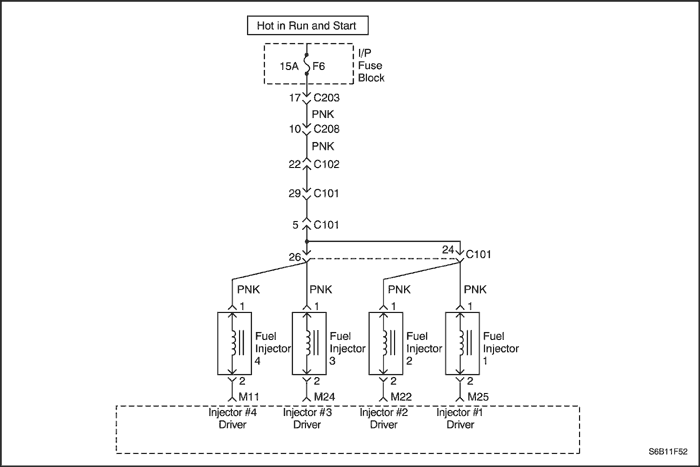
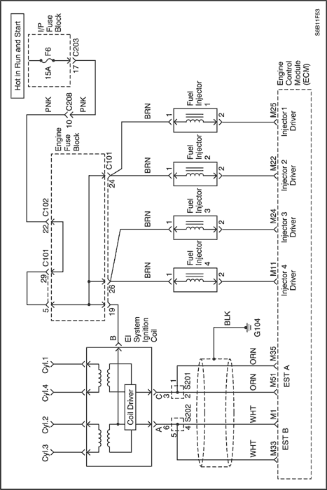
The Engine Control Module (ECM) has four individual injector driver circuits, each of which controls an injector. When a driver circuit is grounded by the ECM, the injector is activated. The ECM monitors the current in each driver circuit. The ECM measures a voltage drop through a fixed resistor and controls it. The voltage on each driver is monitored to detect a fault. If the voltage is not what the ECM expects to monitor on the circuit, a Diagnostic Trouble Code (DTC) is set. This DTC detects a short to ground and/or an open circuit and short to battery conditions for low-side drive injector outputs.
Conditions for Setting the DTC
- Monitor fault feedback signal from FETS.
- Engine is in run mode.
- Battery voltage is greater than 9 volts.
- Engine speed is greater than 600 rpm.
- Fault is present for more than 5 seconds.
Action Taken When the DTC Sets
- The ECM will illuminate the Malfunction Indicator Lamp (MIL) the first time the fault is Detected.
- The ECM will store conditions which were present when the DTC was set as Freeze Frame and in the Failure Records data.
Conditions for Clearing the MIL/DTC
- The ECM will turn off the MIL on the third consecutive trip cycle in which the diagnostic has been run and the fault is no longer present.
- A history will clear after 40 consecutive warm-up cycles without a fault.
- DTC can be cleared by using the scan tool Clear Info function.
- Disconnecting the ECM battery feed for more than 10 seconds.
Diagnostic Aids
An injector 1 driver circuit that is open or shorted to voltage will cause a DTC P0201 to set. It will also cause a misfire due to an inoperative injector. A misfire DTC should also be set indicating which injector is inoperative.
Long-term and short-term fuel trims that are excessively high or low are a good indication that an injector is malfunctioning. Refer to
"Fuel Injector Balance Test" in this section to check for malfunctioning injectors.
The injector resistance tested at the ECM connection is slightly more than if tested directly at the injector because it includes resistance of the harness wires. The normal value is about 13.5 Ω
Test Description
Number(s) below refer to the step number(s) on the Diagnostic Table.
- The On-Board Diagnostic (EOBD) System Check prompts the technician to complete some basic checks and store the freeze frame and failure records data on the scan tool if applicable. This creates an electronic copy of the data taken when the malfunction occurred. The information is then stored on the scan tool for later reference.
- This step determines if DTC P0201 is the result of a hard failure or an intermittent condition.
- This step tests the wiring harness and the ECM control of the injectors using a test light.
- This step determines if the circuitry is shorted to voltage or the ECM is faulty.
- The replacement ECM must be reprogrammed. Refer to the latest Techline procedure for ECM reprogramming.
DTC P0201 - Injector 1 Control Circuit
| Step | Action | Value(s) | Yes | No |
| 1 | Perform an On-Board Diagnostic (EOBD) System Check. Was the check performed? | - | Go to Step 2 | |
| 2 | Will the engine start? | - | Go to Step 3 | |
| 3 | - Install a scan tool to the Data Link Connector (DLC).
- Turn the ignition ON, with the engine OFF.
- Clear the Diagnostic Trouble Codes (DTCs) using a scan tool.
- Start the engine and idle for one minute.
Does DTC P0201 reset? | - | Go to Step 5 | Go to Step 4 |
| 4 | - Turn the ignition ON, with the engine OFF.
- Review the Freeze Frame data and note the parameters.
- Operate the vehicle within the Freeze Frame conditions as noted.
Does DTC P0201 reset? | - | Go to Step 5 | |
| 5 | - Turn the ignition OFF.
- Disconnect the Engine Control Module (ECM) connector for injector 1.
- Turn the ignition ON, with the engine OFF.
- With a test light connected to ground, probe the driver circuit, terminal M25.
Does the test light illuminate? | - | Go to Step 7 | Go to Step 6 |
| 6 | Repair the short to ground or open in the injector driver circuit. Is the repair complete? | - | Go to Step 10 | - |
| 7 | - Disconnect the injector 1 wiring connection.
- With a test light connected to ground, probe the driver circuit, terminal 2.
Does the test light illuminate? | - | Go to Step 8 | Go to Step 9 |
| 8 | Repair the short to voltage in the injector driver circuit. Is the repair complete? | - | Go to Step 10 | - |
| 9 | - Turn the ignition OFF.
- Replace the ECM.
Is the repair complete? | - | Go to Step 10 | - |
| 10 | - Using the scan tool, clear the DTCs.
- Start the engine and idle at normal operating temperature.
- Operate the vehicle within the Conditions for setting this DTC as specified in the supporting text.
Does the scan tool indicate that this diagnostic has run and passed? | - | Go to Step 10 | Go to Step 2 |
| 11 | Check if any additional DTCs are set. Are any DTCs displayed that have not been diagnosed? | - | Go to applicable DTC table | System OK |
Diagnostic Trouble Code (DTC) P0202
Injector 2 Control Circuit
Circuit Description
The Engine Control Module (ECM) has four individual injector driver circuits, each of which controls an injector. When a driver circuit is grounded by the ECM, the injector is activated. The ECM monitors the current in each driver circuit. The ECM measures a voltage drop through a fixed resistor and controls it. The voltage on each driver is monitored to detect a fault. If the voltage is not what the ECM expects to monitor on the circuit, a Diagnostic Trouble Code (DTC) is set. This DTC detects a short to ground and/or an open circuit and short to battery conditions for low-side drive injector outputs.
Conditions for Setting the DTC
- Monitor fault feedback signal from FETS.
- Engine is in run mode.
- Battery voltage is greater than 9 volts.
- Engine speed is greater than 600 rpm.
- Fault is present for more than 5 seconds.
Action Taken When the DTC Sets
- The ECM will illuminate the Malfunction Indicator Lamp (MIL) the first time the fault is Detected.
- The ECM will store conditions which were present when the DTC was set as Freeze Frame and in the Failure Records data.
Conditions for Clearing the MIL/DTC
- The ECM will turn off the MIL on the third consecutive trip cycle in which the diagnostic has been run and the fault is no longer present.
- A history will clear after 40 consecutive warm-up cycles without a fault.
- DTC can be cleared by using the scan tool Clear Info function.
- Disconnecting the ECM battery feed for more than 10 seconds.
Diagnostic Aids
An injector 2 driver circuit that is open or shorted to voltage will cause a DTC P0202 to set. It will also cause a misfire due to an inoperative injector. A misfire DTC should also be set indicating which injector is inoperative.
Long-term and short-term fuel trims that are excessively high or low are a good indication that an injector is malfunctioning. Refer to
"Fuel injector Balance Test" in this section to check for malfunctioning injectors.
The injector resistance tested at the ECM connection is slightly more than if tested directly at the injector because it includes resistance of the harness wires. The normal value is about 13.5 Ω
Test Description
Number(s) below refer to the step number(s) on the Diagnostic Table.
- The On-Board Diagnostic (EOBD) System Check prompts the technician to complete some basic checks and store the freeze frame and failure records data on the scan tool if applicable. This creates an electronic copy of the data taken when the malfunction occurred. The information is then stored on the scan tool for later reference.
- This step determines if DTC P0201 is the result of a hard failure or an intermittent condition.
- This step tests the wiring harness and the ECM control of the injectors using a test light.
- This step determines if the circuitry is shorted to voltage or the ECM is faulty.
- The replacement ECM must be reprogrammed. Refer to the latest Techline procedure for ECM reprogramming.
DTC P0202 - Injector 2 Control Circuit
| Step | Action | Value(s) | Yes | No |
| 1 | Perform an On-Board Diagnostic (EOBD) System Check. Was the check performed? | - | Go to Step 2 | |
| 2 | Will the engine start? | - | Go to Step 3 | |
| 3 | - Install a scan tool to the Data Link Connector (DLC).
- Turn the ignition ON, with the engine OFF.
- Clear the Diagnostic Trouble Codes (DTCs) using a scan tool.
- Start the engine and idle for one minute.
Does DTC P0202 reset? | - | Go to Step 5 | Go to Step 4 |
| 4 | - Turn the ignition ON, with the engine OFF.
- Review the Freeze Frame data and note the parameters.
- Operate the vehicle within the Freeze Frame conditions as noted.
Does DTC P0202 reset? | - | Go to Step 5 | |
| 5 | - Turn the ignition OFF.
- Disconnect the Engine Control Module (ECM) connector for injector 2.
- Turn the ignition ON, with the engine OFF.
- With a test light connected to ground, probe the driver circuit, terminal M22.
Does the test light illuminate? | - | Go to Step 7 | Go to Step 6 |
| 6 | Repair the short to ground or open in the injector driver circuit. Is the repair complete? | - | Go to Step 10 | - |
| 7 | - Disconnect the injector 2 wiring connection.
- With a test light connected to ground, probe the driver circuit, terminal 2.
Does the test light illuminate? | - | Go to Step 8 | Go to Step 9 |
| 8 | Repair the short to voltage in the injector driver circuit. Is the repair complete? | - | Go to Step 10 | - |
| 9 | - Turn the ignition OFF.
- Replace the ECM.
Is the repair complete? | - | Go to Step 10 | - |
| 10 | - Using the scan tool, clear the DTCs.
- Start the engine and idle at normal operating temperature.
- Operate the vehicle within the Conditions for setting this DTC as specified in the supporting text.
Does the scan tool indicate that this diagnostic has run and passed? | - | Go to Step 10 | Go to Step 2 |
| 11 | Check if any additional DTCs are set. Are any DTCs displayed that have not been diagnosed? | - | Go to applicable DTC table | System OK |
Diagnostic Trouble Code (DTC) P0203
Injector 3 Control Circuit
Circuit Description
The Engine Control Module (ECM) has four individual injector driver circuits, each of which controls an injector. When a driver circuit is grounded by the ECM, the injector is activated. The ECM monitors the current in each driver circuit. The ECM measures a voltage drop through a fixed resistor and controls it. The voltage on each driver is monitored to detect a fault. If the voltage is not what the ECM expects to monitor on the circuit, a Diagnostic Trouble Code (DTC) is set. This DTC detects a short to ground and/or an open circuit and short to battery conditions for low-side drive injector outputs.
Conditions for Setting the DTC
- Monitor fault feedback signal from FETS.
- Engine is in run mode.
- Battery voltage is greater than 9 volts.
- Engine speed is greater than 600 rpm.
- Fault is present for more than 5 seconds.
Action Taken When the DTC Sets
- The ECM will illuminate the Malfunction Indicator Lamp (MIL) the first time the fault is Detected.
- The ECM will store conditions which were present when the DTC was set as Freeze Frame and in the Failure Records data.
Conditions for Clearing the MIL/DTC
- The ECM will turn off the MIL on the third consecutive trip cycle in which the diagnostic has been run and the fault is no longer present.
- A history DTC will clear after 40 consecutive warm-up cycles without a fault.
- DTC can be cleared by using the scan tool Clear Info function.
- Disconnecting the ECM battery feed for more than 10 seconds.
Diagnostic Aids
An injector 3 driver circuit that is open or shorted to voltage will cause a DTC P0203 to set. It will also cause a misfire due to an inoperative injector. A misfire DTC should also be set indicating which injector is inoperative.
Long-term and short-term fuel trims that are excessively high or low are a good indication that an injector is malfunctioning. Refer to
"Fuel injector Balance Test" in this section to check for malfunctioning injectors.
The injector resistance tested at the ECM connection is slightly more than if tested directly at the injector because it includes resistance of the harness wires. The normal value is about 13.5 Ω.
Test Description
Number(s) below refer to the step number(s) on the Diagnostic Table.
- The On-Board Diagnostic (EOBD) System Check prompts the technician to complete some basic checks and store the freeze frame and failure records data on the scan tool if applicable. This creates an electronic copy of the data taken when the malfunction occurred. The information is then stored on the scan tool for later reference.
- This step determines if DTC P0203 is the result of a hard failure or an intermittent condition.
- This step tests the wiring harness and ECM control of the injectors using a test light.
- This step determines if the circuitry is shorted to voltage or the ECM is faulty.
- The replacement ECM must be reprogrammed. Refer to the latest Techline procedure for ECM reprogramming.
DTC P0203 - Injector 3 Control Circuit
| Step | Action | Value(s) | Yes | No |
| 1 | Perform an On-Board Diagnostic (EOBD) System Check. Was the check performed? | - | Go to Step 2 | |
| 2 | Will the engine start? | - | Go to Step 3 | |
| 3 | - Install a scan tool to the Data Link Connector DLC).
- Turn the ignition ON, with the engine OFF.
- Clear the Diagnostic Trouble Codes (DTCs) using a scan tool.
- Start the engine and idle for one minute.
Does DTC P0203 reset? | - | Go to Step 5 | Go to Step 4 |
| 4 | - Turn the ignition ON, with the engine OFF.
- Review the Freeze Frame data and note the parameters.
- Operate the vehicle within the Freeze Frame conditions as noted.
Does DTC P0203 reset? | - | Go to Step 5 | |
| 5 | - Turn the ignition OFF.
- Disconnect the Engine Control Module (ECM) connector for injector 3.
- Turn the ignition ON, with the engine OFF.
- With a test light connected to ground, probe the driver circuit, terminal M24.
Does the test light illuminate? | - | Go to Step 7 | Go to Step 6 |
| 6 | Repair the short to ground or open in the injector driver circuit. Is the repair complete? | - | Go to Step 10 | - |
| 7 | - Disconnect the injector 3 wiring connection.
- With a test light connected to ground, probe the driver circuit, terminal 2.
Does the test light illuminate? | - | Go to Step 8 | Go to Step 9 |
| 8 | Repair the short to voltage in the injector driver circuit. Is the repair complete? | - | Go to Step 10 | - |
| 9 | - Turn the ignition OFF.
- Replace the ECM.
Is the repair complete? | - | Go to Step 10 | - |
| 10 | - Using the scan tool, clear the DTCs.
- Start the engine and idle at normal operating temperature.
- Operate the vehicle within the Conditions for setting this DTC as specified in the supporting text.
Does the scan tool indicate that this diagnostic has run and passed? | - | Go to Step 10 | Go to Step 2 |
| 11 | Check if any additional DTCs are set. Are any DTCs displayed that have not been diagnosed? | - | Go to applicable DTC table | System OK |
Diagnostic Trouble Code (DTC) P0204
Injector 4 Control Circuit
Circuit Description
The Engine Control Module (ECM) has four individual injector driver circuits, each of which controls an injector. When a driver circuit is grounded by the ECM, the injector is activated. The ECM monitors the current in each driver circuit. The ECM measures a voltage drop through a fixed resistor and controls it. The voltage on each driver is monitored to detect a fault. If the voltage is not what the ECM expects to monitor on the circuit, a Diagnostic Trouble Code (DTC) is set. This DTC detects a short to ground and/or an open circuit and short to battery conditions for low-side drive injector outputs.
Conditions for Setting the DTC
- Monitor fault feedback signal from FETS.
- Engine is in run mode.
- Battery voltage is greater than 9 volts.
- Engine speed is greater than 600 rpm.
- Fault is present for more than 5 seconds.
Action Taken When the DTC Sets
- The ECM will illuminate the Malfunction Indicator Lamp (MIL) the first time the fault is Detected.
- The ECM will store conditions which were present when the DTC was set as Freeze Frame and in the Failure Records data.
Conditions for Clearing the MIL/DTC
- The ECM will turn off the MIL on the third consecutive trip cycle in which the diagnostic has been run and the fault is no longer present.
- A history DTC will clear after 40 consecutive warm-up cycles without a fault.
- DTC can be cleared by using the scan tool Clear Info function.
- Disconnecting the ECM battery feed for more than 10 seconds.
Diagnostic Aids
An injector 4 driver circuit that is open or shorted to voltage will cause a DTC P0204 to set. It will also cause a misfire due to an inoperative injector. A misfire DTC should also be set indicating which injector is inoperative.
Long-term and short-term fuel trims that are excessively high or low are a good indication that an injector is malfunctioning. Refer to
"Fuel injector Balance Test" in this section to check for malfunctioning injectors.
The injector resistance tested at the ECM connection is slightly more than if tested directly at the injector because it includes resistance of the harness wires. The normal value is about 13.5 Ω.
Test Description
Number(s) below refer to the step number(s) on the Diagnostic Table.
- The On-Board Diagnostic (EOBD) System Check prompts the technician to complete some basic checks and store the freeze frame and failure records data on the scan tool if applicable. This creates an electronic copy of the data taken when the malfunction occurred. The information is then stored on the scan tool for later reference.
- This step determines if DTC P0204 is the result of a hard failure or an intermittent condition.
- This step tests the wiring harness and ECM control of the injectors using a test light.
- This step determines if the circuitry is shorted to voltage or the ECM is faulty.
- The replacement ECM must be reprogrammed. Refer to the latest Techline procedure for ECM reprogramming.
DTC P0204 - Injector 4 Control Circuit
| Step | Action | Value(s) | Yes | No |
| 1 | Perform an On-Board Diagnostic (EOBD) System Check. Was the check performed? | - | Go to Step 2 | |
| 2 | Will the engine start? | - | Go to Step 3 | |
| 3 | - Install a scan tool to the Data Link Connector (DLC).
- Turn the ignition ON, with the engine OFF.
- Clear the Diagnostic Trouble Codes (DTCs) using a scan tool.
- Start the engine and idle for one minute.
Does DTC P0204 reset? | - | Go to Step 5 | Go to Step 4 |
| 4 | - Turn the ignition ON, with the engine OFF.
- Review the Freeze Frame data and note the parameters.
- Operate the vehicle within the Freeze Frame conditions as noted.
Does DTC P0204 reset? | - | Go to Step 5 | |
| 5 | - Turn the ignition OFF.
- Disconnect the Engine Control Module (ECM) connector for injector 4.
- Turn the ignition ON, with the engine OFF.
- With a test light connected to ground, probe the driver circuit, terminal M11.
Does the test light illuminate? | - | Go to Step 7 | Go to Step 6 |
| 6 | Repair the short to ground or open in the injector driver circuit. Is the repair complete? | - | Go to Step 10 | - |
| 7 | - Disconnect the injector 4 wiring connection.
- With a test light connected to ground, probe the driver circuit, terminal 2.
Does the test light illuminate? | - | Go to Step 8 | Go to Step 9 |
| 8 | Repair the short to voltage in the injector driver circuit. Is the repair complete? | - | Go to Step 10 | - |
| 9 | - Turn the ignition OFF.
- Replace the ECM.
Is the repair complete? | - | Go to Step 10 | - |
| 10 | - Using the scan tool, clear the DTCs.
- Start the engine and idle at normal operating temperature.
- Operate the vehicle within the Conditions for setting this DTC as specified in the supporting text.
Does the scan tool indicate that this diagnostic has run and passed? | - | Go to Step 10 | Go to Step 2 |
| 11 | Check if any additional DTCs are set. Are any DTCs displayed that have not been diagnosed? | - | Go to applicable DTC table | System OK |
Diagnostic Trouble Code (DTC) P0300
Engine Misfire Detected
System Description
The Engine Control Module (ECM) monitors the crankshaft and camshaft positions to detect if the engine is misfiring. The ECM looks for a quick drop in crankshaft speed. This test is executed in blocks of 100 engine revolution tests. It may take between one to several tests to store a Diagnostic Trouble Code (DTC) and illuminate the Malfunction Indicator Lamp (MIL). Under light misfire conditions, it may also take more than one trip to set a DTC. Severe misfire will flash the MIL, indicating that catalyst damage is possible.
Conditions for Setting the DTC
- Emission threshold is 2.75% for manual transaxle and 2.0% for automatic transaxle.
- 20 engine cycles have occurred since cranking has started.
- A/C compressor clutch has not just engaged or disengaged.
- Engine load and engine speed is in a detectable region and is at or above zero torque.
- Camshaft Position (CMP) sensor is in synchronization.
- Exhaust Gas Recirculation (EGR) flow diagnostic is not in progress.
- Fuel level is greater than 11% of rated tank capacity.
- Decel Fuel Cutoff (DFCO) not active.
- Fuel is not shutoff from high engine speed of 6500 rpm.
- Fuel is not shutoff at 255 km/h (158 mph).
- Throttle position change is less than 3% per 125 ms.
- Vehicle has not encountered an abusive engine speed of 7000 rpm.
- Crankshaft speed patters are normal.
- Throttle position is less than 4% when vehicle speed is greater than 10 km/h (6 mph).
- Engine speed is between 600 and 4500 rpm.
- Vehicle voltage is between 11 and 16 volts.
- Engine Coolant Temperature (ECT) is between .-7°C (19°F) and 120°C (248°F).
- The engine speed is less than or equal to 1800 rpm at the TEC(Tooth Error Correction) has not been learned.
- There is the correct ratio between Crankshaft Position (CKP) sensor pulses and CMP sensor pulses.
- DTCs P0106, P0107, P0108, P0117, P0118, P0122, P0123, P0336, P0337, P0341, P0342 and P0502 are not set.
Action Taken When the DTC Sets
- The MIL will illuminate after two consecutive ignition cycles in which the diagnostic runs with the fault active.
Or
- The MIL will illuminate immediately and flash if misfire is present.
- The ECM will record operating conditions at the time the diagnostic fails. This information will be stored in the Freeze Frame and Failure Records buffers.
- A history DTC is stored.
Conditions for Clearing the MIL/DTC
- The MIL will turn off after four consecutive ignition cycles in which the diagnostic runs without a fault within the freeze frame conditions that the DTC failed.
- A history DTC will clear after 40 consecutive warm-up cycles without a fault.
- The DTC(s) can be cleared by using the scan tool.
- Disconnecting the ECM battery feed for more than 10 seconds.
Diagnostic Aids
An intermittent can also be the result of a defective reluctor wheel. Remove the CKP sensor and inspect the reluctor wheel through the sensor mount hole. Check for porosity and the condition of wheel. If the DTC is intermittent refer to
"Symptoms Diagnosis" in this section.
Test Description
Number(s) below refer to the step number(s) on the Diagnostic Table.
- The On-Board Diagnostic (EOBD) System Check prompts the technician to complete some basic checks and store the freeze frame and failure records data on the scan tool if applicable. This creates an electronic copy of the data taken when the malfunction occurred. The information is then stored on the scan tool for later reference.
- A visual/physical inspection should include checking the following components:
- The wiring for proper connections, pinches or cuts.
- The ECM grounds for being clean and tight.
- The vacuum hoses for splits, kinks, and proper connections as shown on the Vehicle Emission Information label. Check thoroughly for any type of leak or restriction.
- For air leaks at the throttle body mounting area and intake manifold sealing surfaces.
- When all the accumulators are relatively equal, then the misfire is being caused by something that affects the entire engine. When they are not then the misfire is being caused by something that is specific to two or more cylinders.
- Whenever the misfire is not present operating the vehicle may be necessary to duplicate the conditions in the Freeze Frame Data in order to detect misfire. Depending on the engine load, the conditions may have to be maintained for up to 20 seconds. Whenever the misfire accumulators start to increment, then misfire is present. A history misfire counter will store the number of misfires that have occurred until the DTC is cleared.
- Check fuel for water, alcohol, etc.
- A basic engine problem that affects all cylinders is the only possibility at this point. (Cam timing, throttle body leak, restricted air flow, etc.)
- Tests the ignition system voltage output using a spark tester.
- Replace any spark plugs that are worn, cracked or fouled.
- Checks for voltage at the ignition feed circuit.
- Whenever the driver circuit is shorted to ground, the light will be on steady. When the driver circuit is shorted to voltage or open, the light will be off.
- Since voltage is supplied to the fuel injector on a single circuit, the malfunction could only be a poor connection or open in the fuel injector harness. An open before the harness would result in an "Engine Cranks But Will Not Run" complaint.
- Before replacing the ECM, check terminals for improper mating, broken locks, or physical damage to the wiring harness. The replacement ECM must be reprogrammed. Refer to the latest Techline procedure for ECM reprogramming.
DTC P0300 - Engine Misfire Detected
| Step | Action | Value(s) | Yes | No |
| 1 | Perform an On-Board Diagnostic (EOBD) System Check. Was the check performed? | - | Go to Step 2 | |
| 2 | - Install a scan tool to the Data Link Connector (DLC).
- Turn the ignition ON, with the engine OFF.
- Request Diagnostic Trouble Codes (DTCs)
Are DTCs P0201, P0202, P0203, P0204 set? | - | Go to applicable DTC | Go to Step 3 |
| 3 | - Perform a visual/physical inspection.
- Make any repairs that are necessary.
Is the repair complete? | - | Go to Step 27 | Go to Step 4 |
| 4 | Start the engine and allow it to idle. Are any Misfire Current counters incrementing? | - | Go to Step 5 | Go to Step 6 |
| 5 | Are all counters equal (within a percentage of each other)? | - | Go to Step 7 | Go to Step 11 |
| 6 | - Turn the ignition ON, with the engine OFF.
- Review the Freeze Frame data, and note the parameters.
- Operate the vehicle within the Freeze Frame conditions and conditions for setting this DTC as noted.
Are any Misfire Current counters incrementing? | - | Go to Step 5 | |
| 7 | - Turn the engine OFF.
- Install a fuel pressure gauge to the fuel rail.
- Observe the fuel pressure with the engine running.
Is the fuel pressure within the specified value? | 284-325 kPa (41-47 psi) | Go to Step 8 | |
| 8 | Check the fuel for contamination. Is the fuel OK? | - | Go to Step 9 | Go to Step 10 |
| 9 | Check for a basic engine problem and repair as necessary. Is the repair complete? | - | Go to Step 27 | - |
| 10 | Replace the contaminated fuel. Is the repair complete? | - | Go to Step 27 | - |
| 11 | - Turn the engine OFF.
- Disconnect the fuel injector harness connector.
- Install a spark tester on cylinder #1 spark plug cable.
- Crank the engine and check for spark.
- Repeat the above procedure on cylinders #2, #3 and #4.
Is a spark observed on all four spark plug cables? | - | Go to Step 12 | Go to Step 20 |
| 12 | Replace any malfunctioning spark plugs if necessary. Is the repair complete? | - | Go to Step 27 | Go to Step 13 |
| 13 | - Turn the engine OFF.
- Disconnect the fuel injector connectors from the injectors.
- Install an injector test light on the injector harness connector for the cylinders that had misfired.
- Crank the engine and note the test light.
Does the injector test light blink? | - | Go to Step 14 | Go to Step 15 |
| 14 | Perform the Fuel Injector Balance Test. Are the fuel injectors OK? | - | Go to Step 9 | Go to Step 16 |
| 15 | - Disconnect the injector test light.
- With a test light connected to ground, probe the ignition feed terminal 1 of the injector harness connector for each cylinder that had misfire.
- Crank the engine.
Does the test light illuminate? | - | Go to Step 17 | Go to Step 19 |
| 16 | Replace any malfunctioning fuel injectors. Is the repair complete? | - | Go to Step 27 | - |
| 17 | Check the affected fuel injector driver circuit at terminals M25, M22, M24, and M11 for an open, short, or short to voltage. Is a problem found? | - | Go to Step 18 | Go to Step 24 |
| 18 | Repair the open or the shorted fuel injector driver circuit. Is the repair complete? | - | Go to Step 26 | - |
| 19 | Repair the open ignition feed circuit between the fuel injector harness connector and the fuel injector connector. Is the repair complete? | - | Go to Step 27 | - |
| 20 | Measure the resistance of the spark plug cable that the spark plug tester did not spark. Is the resistance of the spark plug cable less than the specified value? | 30,000 Ω | Go to Step 21 | Go to Step 25 |
| 21 | Inspect the Engine Control Module (ECM) connector and connections. Are the connections OK? | - | Go to Step 22 | Go to Step 23 |
| 22 | Check the affected cylinders ignition control circuit for an open or short and repair as necessary. Is the repair complete? | - | Go to Step 27 | Go to Step 26 |
| 23 | Repair the connector or connections. Is the repair complete? | - | Go to Step 27 | - |
| 24 | - Turn the ignition OFF.
- Replace the ECM.
Is the repair complete? | - | Go to Step 27 | - |
| 25 | Replace the spark plug cable. Is the repair complete? | - | Go to Step 27 | - |
| 26 | Replace the faulty ignition coil. Is the repair complete? | - | Go to Step 27 | Go to Step 24 |
| 27 | - Using the scan tool, clear the DTCs.
- Start the engine and idle at normal operating temperature.
- Operate the vehicle within the conditions for setting this DTC as supported in the text.
Does the scan tool indicate that this diagnostic ran and passed? | - | Go to Step 28 | Go to Step 2 |
| 28 | Check if any additional DTCs are set. Are any DTCs displayed that have not been diagnosed? | - | Go to Applicable DTC table | System OK |
 | |  | |
| © Copyright Chevrolet Europe. All rights reserved |