Diagnostic Trouble Code (DTC) P0315
Crankshaft Position (CKP) System Variation Not Learned
Circuit Description
In order to detect engine misfire at higher enginespeeds, the Engine Control Module (ECM) must know ofany variation between the crankshaft sensor pulses.Most variations are due to the machining of the crankshaftreluctor wheel. However, other sources of variationare also possible. A Crankshaft Position (CKP) systemvariation learning procedure must be performed anytime a change is made to the crankshaft sensor tocrankshaft relationship of if the ECM is replaced or reprogrammed.The ECM measures the variations andthen calculates compensation factors needed to enablethe ECM to accurately detect engine misfire at allspeeds and loads. A scan tool must be used to commandthe ECM to learn these variations. If for any reasonthe ECM is unable to learn these variations or theyare out of an acceptable range, the ECM will set DiagnosticTrouble Code (DTC). An ECM that has nothad the CKP system variation learning procedure performeddue to replacement or reprogramming will alsoset a DTC.
Conditions for Setting the DTC
- Tooth error not learned if the manufacture enablecounter is set to zero.
- DTCs P0106, P0107, P0108, P0117, P0118, P0122,P0123, P0132, P0201, P0202, P0203, P0204, P0325, P0336, P0351, P0352,P0402, P0404, P0405, P0406 and P0502 are not set.
Action Taken When the DTC Sets
- The Malfunction Indicator Lamp (MIL) will illuminate.
- The ECM will record operating conditions at the timethe diagnostic fails. This information will be stored inthe Freeze Frame and Failure Records buffer.
- A history DTC is stored.
Conditions for Clearing the MIL/DTC
- The MIL will turn OFF after four consecutive ignitioncycles in which the diagnostic runs without a fault.
- A history DTC will clear after 40 consecutive warm up cycles without a fault.
- Disconnecting the ECM battery feed for more than 10seconds.
- DTC(s) can be cleared by using the scan tool.
Diagnostic Aids
Caution : To avoid personal injury when performing the crankshaft position system variation learning procedure, always set the vehice parking brake and block the drive wheels. Release the throttle immediately when the engine starts to decelerate. Once the learn procedure is completed, engine control will be returned to the operator, and the engine will respond to throttle position.
DTC P0315 will only set if the ECM has not learned the CKP system variation. The ECM only needs to learn this variation once per life cycle of the vehicle unless the crank sensor to crankshaft relationship is disturbed. Removing a part is considered a disturbance. A fully warmed engine is critical to learning the variation correctly. If a valid learn occurs, no other learns can be completed that ignition cycle.
If the engine cuts out before the specified learn procedure engine speed or at normal fuel cutoff rpm, the ECM is not in the learn procedure mode.
Test Description
The number(s) below refer to step(s) on the diagnostic table.
- The On-Board Diagnostic (EOBD) System Checkprompts the technician to complete some basicchecks and store the freeze frame and failure recordsdata on the scan tool if applicable. This creates anelectronic copy of the data taken when the fault occurred.The information is then stored on the scantool for later reference.
- Engine temperature is critical to properly learn theCKP system variation. Failure to properly warm theengine before performing this procedure will result inan inaccurate measurement of the CKP system variation.The ECM learns this variation as the engine is decelerating and then allows engine control to be returnedto the operator. All accessories must be OFFwhen learning the CKP system angle variation. If theA/C is not disabled when the learn procedure is enabled,the ECM will disable the A/C.
- If after the specified number attempts the ECM cannotlearn the CKP system variation, then the variation is too large and no further attempts should be madeuntil the variation problem is corrected.
- Being unable to learn the procedure indicates that thevariation is out of range.
- After the CKP system variation has been learned, wait above 10 seconds with ignition switch OFF to prevent being cleared the learned value.
DTC P0315 - Crankshaft Position (CKP) System Variation Not Learned
| Step | Action | Value(s) | Yes | No |
| 1 | Perform an On-Board Diagnostic (EOBD) System Check. Is the system check complete? | - | Go to Step 2 | |
| 2 | - Turn the ignition OFF.
- Install a scan tool to the Data Link Connector(DLC).
- Put the vehicle in PARK or NEUTRAL.
- Start the engine and operate to normal operatingtemperature.
- Turn all accessories OFF.
- Enable the TEC (Tooth Error Correction) LEARNPROCEDURE with the scan tool.
- Raise the engine rpm to the specified value, thenrelease the throttle as soon as the engine cutsout.
Does the scan tool indicate that the Crankshaft Position (CKP) system variation has been learned? | 65°C (149°F) 4000 rpm | Go to Step 5 | Go to Step 3 |
| 3 | Attempt the CKP system variation procedure as many times as the specified value. Does the scan tool indicate that the CKP system variation has been learned? | 10 | Go to Step 5 | Go to Step 4 |
| 4 | Check for a problem with the CKP sensor tocrankshaft relationship. Is the repair complete? | - | Go to Step 5 | - |
| 5 | - Turn the ignition OFF and wait above specifiedvalue.
- Turn the ignition ON, with engine OFF.
- Using the scan tool, clear the Diagnostic TroubleCodes (DTCs).
- Start the engine and idle at normal operatingtemperature.
- Operate the vehicle within the conditions forsetting this DTC as supported in the text.
Does the scan tool indicate that this diagnostic ran and passed? | 10 sec | Go to Step 6 | Go to Step 2 |
| 6 | Check if any additional DTCs are set. Are any DTCs displayed that have not been diagnosed? | - | Go to Applicable DTC table | System OK |
Diagnostic Trouble Code (DTC) P0317
System Description
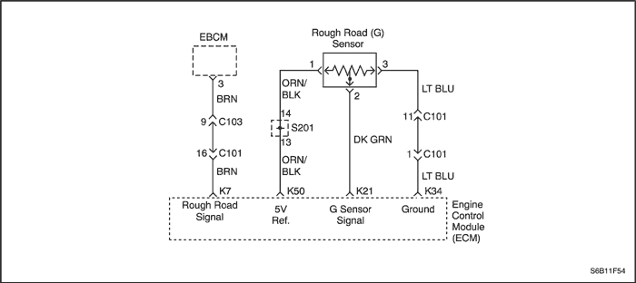
The Engine Control Module (ECM) identifies engine misfire by detecting variations in crankshaft speed. Crankshaft speed variations can also occur when a vehicle is operating over a rough road. The ECM receives rough road signal by gravity sensing rough road (G) sensor or Electronic Brake Control Module (EBCM) if equipped with the Anti-Lock Brake System (ABS). The ABS can detect if the vehicle is on the rough surface based on wheel acceleration/deceleration data supplied by each wheel speed sensor. This information sent to the ECM by EBCM through serial data line. The G sensor is vertical low g-acceleration sensor. By sensing vertical acceleration caused by bumps or portholes in the road, the ECM determine if the changes in crankshaft speed are due to engine misfire or are driveline induced. If the ECM can not receive any of those signal, a historic Diagnostic Trouble Code (DTC) will be stored.
Conditions for Setting the DTC
- ECM can not detect any rough road source.
- Engine run time is greater than or equal to 10 seconds.
Action Taken When the DTC Sets
- The MIL will not illuminate.
- The ECM will record operating conditions at the time the diagnostic fails. This information will be stored in the Failure Records buffers.
- A history DTC is stored.
Conditions for Clearing the MIL/DTC
- A history DTC will clear after 40 consecutive warm-up cycles without a fault.
- The DTC(s) can be cleared by using the scan tool.
- Disconnecting the ECM battery feed for more than 10 seconds.
Diagnostic Aids
An open signal circuit of G sensor or open serial data line between the ECM and the EBCM will be the cause of this DTC.
DTC P0317 - Rough Road Sensing System Input Not Present
| Step | Action | Value(s) | Yes | No |
| 1 | Perform an On-Board Diagnostic (EOBD) System Check. Was the check complete? | - | Go to Step 2 | |
| 2 | - Install a scan tool to the Data Link Connector (DLC).
- Turn the ignition ON, with the engine OFF.
- Request Diagnostic Trouble Codes (DTCs)
Are DTCs P1391, P1392 or P1393 set? | - | Go to Applicable DTC | Go to Step 3 |
| 3 | Is the vehicle equipped with the Anti-lock Brake System (ABS)? | - | Go to Step 8 | Go to Step 4 |
| 4 | - Disconnect the gravity sensing rough road (G) sensor connector.
- Disconnect the Engine control Module (ECM) connector.
- Measure resistance between terminal 2 of the G sensor and terminal K21 of the ECM.
Is the resistance within the specified value? | 0 Ω | Go to Step 6 | Go to Step 5 |
| 5 | Repair open circuit. Is the repair complete? | - | Go to Step 11 | Go to Step 6 |
| 6 | - Reconnect the ECM and G sensor connectors.
- Turn the ignition ON.
- Probe the voltage at terminal 2 of G sensor.
Is the voltage within the specified value? | 2.35-2.65 V | Go to Step 10 | Go to Step 7 |
| 7 | - Turn the ignition OFF.
- Replace the G sensor.
Is the repair complete? | - | Go to Step 11 | - |
| 8 | - Turn the ignition OFF.
- Disconnect the Electronic Brake Control Module EBCM) connector and the ECM connector.
- Measure the resistance between terminal 35 of the EBCM and terminal K7 of the ECM.
Is the resistance within the specified value? | 0 Ω | Go to Step 10 | Go to Step 9 |
| 9 | Repair open circuit. Is the repair complete? | - | Go to Step 11 | Go to Step 10 |
| 10 | - Turn the ignition OFF.
- Replace the ECM.
Is the repair complete? | - | Go to Step 11 | - |
| 11 | - Using the scan tool, clear the DTCs.
- Start the engine and idle at normal operating temperature.
- Operate the vehicle within the conditions for setting this DTC as supported in the text.
Does the scan tool indicate that this diagnostic ran and passed? | - | Go to Step 12 | Go to Step 2 |
| 12 | Check if any additional DTCs are set. Are any DTCs displayed that have not been diagnosed? | - | Go to Applicable DTC table | System OK |
Diagnostic Trouble Code (DTC) P0324
Knock Sensor (KS) Module Performance
System Description
The Knock Sensor (KS) system is used to detect engine detonation, allowing the Engine Control Module (ECM) to retard the ignition control spark timing based on the KS signal being received. The KS produces an AC signal so that under a no-knock condition the signal on the KS circuit measures about 0.007 volts AC. The KS signal's amplitude and frequency depend upon the amount of knock being experienced. The ECM contains a nonreplaceable knock filter module called a Digitally Controlled Signal-to-Noise Enhancement Filter (DSNEF) module. This filter module in the ECM determines whether or not knock is occurring by comparing the signal level on the KS circuit with the voltage level on the noise channel. The noise channel allows the ECM to reject any false knock signal by knowing the amount of normal engine mechanical noise present. Normal engine noise varies depending on engine speed and load. When the ECM determines that an abnormally low noise channel voltage level is being experienced, Diagnostic Trouble Code (DTC) will set.
Conditions for Setting the DTC
- Intensity average reading is less than 1.0% or greater than 80% for any of the 4 cylinders.
- Vacuum is less than the predetermined value (10 to 50 kPa, based on rpm).
- The rpm is greater than 1600.
- Engine Coolant Temperature (ECT) is greater than 60°C.
Action Taken When the DTC Sets
- The Malfunction Indicator Lamp (MIL) will not illuminate.
- The ECM will record operating conditions at the time the diagnostic fails. This information will be stored in the Failure Records buffers.
- A history DTC is stored.
Conditions for Clearing the MIL/DTC
- A history DTC will clear after 40 consecutive warm-up cycles without a fault.
- DTC(s) can be cleared by using the scan tool.
- Disconnecting the ECM battery feed for more than 10 seconds.
Diagnostic Aids
Check and correct any abnormal engine noise before using the diagnostic table.
Any circuitry, that is suspected as causing the complaint, should be thoroughly checked for the following conditions:
- Backed-out terminals
- Improper mating
- Broken locks
- Improperly formed
- Damaged terminals
- Poor terminal-to-wire connection
- Physical damage to the wiring harness
Test Description
Number(s) below refer to the step number(s) on the Diagnostic Table.
- The On-Board Diagnostic (EOBD) System Check prompts the technician to complete some basic checks and store the freeze frame and failure records data on the scan tool if applicable. This creates an electronic copy of the data taken when the malfunction occurred. The information is then stored on the scan tool for later reference.
- If the conditions for the test as described above are met, a DTC will set and MIL will illuminate.
- If the engine has an internal knock or audible noise that causes a knocking type noise on the engine block, the knock sensor may be responding to the noise.
- The replacement ECM must be reprogrammed. Refer to the latest Techline procedure for ECM reprogramming.
DTC P0324 - Knock Sensor (KS) Module Performance
| Step | Action | Value(s) | Yes | No |
| 1 | Perform an On-Board Diagnostic (EOBD) System Check. Was the check performed? | - | Go to Step 2 | |
| 2 | - Install a scan tool to the Data Link Connector (DLC).
- Clear the Diagnostic Trouble Codes (DTCs).
- Start the engine.
- Operate the vehicle within the Conditions for Setting the DTC as noted.
Is the DTC set again. | - | Go to Step 3 | Go to Step 6 |
| 3 | Listen to the engine while rising and lowing the engine speed. Is a knock or audible noise present? | - | Go to Step 4 | Go to Step 5 |
| 4 | Repair mechanical engine problem or a loose bracket or components as needed. Is the repair complete? | - | Go to Step 6 | - |
| 5 | - Turn the ignition OFF.
- Replace the ECM.
Is the repair complete? | - | Go to Step 6 | - |
| 6 | - Using the scan tool, clear the DTCs.
- Start the engine and idle at normal operating temperature.
- Operate the vehicle within the conditions for setting this DTC as supported in the text.
Does the scan tool indicate that this diagnostic ran and passed? | - | Go to Step 7 | Go to Step 2 |
| 7 | Check if any additional DTCs are set. Are any DTCs displayed that have not been diagnosed? | - | Go to Applicable DTC table | System OK |
Diagnostic Trouble Code (DTC) P0325
Knock Sensor (KS) Circuit
System Description
The Knock Sensor (KS) system is used to detect engine detonation, allowing the Engine Control Module (ECM) to retard the ignition control spark timing based on the KS signal being received. The KS produces an AC signal so that under a no-knock condition the signal on the KS circuit measures about 0.007 volts AC. The KS signal's amplitude and frequency depend upon the amount of knock being experienced. The ECM monitors the KS signal and can diagnose the KS and circuitry.
Conditions for Setting the DTC
- Minimum intensity difference between cylinders is less than 0.4%.
- Vacuum is less than the predetermined value (10 to 50 kPa, based on rpm).
- The rpm is greater than 1600.
- Engine Coolant Temperature (ECT) is greater than 66°C (151°F).
Action Taken When the DTC Sets
- The Malfunction Indicator Lamp (MIL) will not illuminate.
- The ECM will record operating conditions at the time the diagnostic fails. This information will be stored in the Failure Records buffers.
- A history DTC is stored.
Conditions for Clearing the MIL/DTC
- A history DTC will clear after 40 consecutive warm-up cycles without a fault.
- DTC(s) can be cleared by using the scan tool.
- Disconnecting the ECM battery feed for more than 10 seconds.
Diagnostic Aids
Check and correct any abnormal engine noise before using the diagnostic table.
Any circuitry, that is suspected as causing the complaint, should be thoroughly checked for the following conditions:
- Backed-out terminals
- Improper mating
- Broken locks
- Improperly formed
- Damaged terminals
- Poor terminal-to-wire connection
- Physical damage to the wiring harness
Test Description
Number(s) below refer to the step number(s) on the Diagnostic Table.
- The On-Board Diagnostic (EOBD) System Check prompts the technician to complete some basic checks and store the freeze frame and failure records data on the scan tool if applicable. This creates an electronic copy of the data taken when the malfunction occurred. The information is then stored on the scan tool for later reference.
- If the conditions for the test as described above are met, a DTC will set and MIL will illuminate.
- If the engine has an internal knock or audible noise that causes a knocking type noise on the engine block, the KS may be responding to the noise.
- Checking the internal resistance of the KS or the wiring to the KS is OK.
- Any circuitry, that is suspected as causing the complaint, should be thoroughly checked for backed-out terminals, improper mating, broken locks, improperly formed or damaged terminals, poor terminal-to-wiring connections or physical damage to the wiring harness.
- The replacement ECM must be reprogrammed. Refer to the latest Techline procedure for ECM reprogramming.
DTC P0325 - Knock Sensor (KS) Circuit
| Step | Action | Value(s) | Yes | No |
| 1 | Perform an On-Board Diagnostic (EOBD) System Check. Was the check performed? | - | Go to Step 2 | |
| 2 | - Install a scan tool to the Data Link Connector (DLC).
- Clear the Diagnostic Trouble Codes (DTCs).
- Start the engine.
- Operate the vehicle within the Conditions for Setting the DTC as noted.
Is the DTC set again. | - | Go to Step 3 | Go to Step 6 |
| 3 | Listen to the engine while rising and lowing the engine speed. Is a knock or audible noise present? | - | Go to Step 4 | Go to Step 5 |
| 4 | Repair mechanical engine problem or a loose bracket or components as needed. Is the repair complete? | - | Go to Step 11 | - |
| 5 | - Turn the ignition OFF.
- Disconnect the Engine Control Module (ECM) connector.
- With a ohmmeter connected ground, measure the resistance of the Knock Sensor (KS) through the KS signal circuit, terminal M18.
Is the resistance between the specified value? | 90-110 kΩ | Go to Step 6 | Go to Step 8 |
| 6 | Check for a poor connection at the ECM connector KS signal circuit and repair as needed. Is the repair complete? | - | Go to Step 11 | Go to Step 7 |
| 7 | - Turn the ignition OFF.
- Replace the ECM.
Is the repair complete? | - | Go to Step 11 | - |
| 8 | Check the KS connector for a poor connection and repair as needed. Is the repair complete? | - | Go to Step 11 | Go to Step 9 |
| 9 | Check the KS signal circuit for an open or a short to ground or voltage and repair as needed. Is the repair complete? | - | Go to Step 11 | - |
| 10 | - Turn the ignition OFF.
- Replace the KS.
Is the repair complete? | - | Go to Step 11 | - |
| 11 | - Using the scan tool, clear the DTCs.
- Start the engine and idle at normal operating temperature.
- Operate the vehicle within the conditions for setting this DTC as supported in the text.
Does the scan tool indicate that this diagnostic ran and passed? | - | Go to Step 12 | Go to Step 2 |
| 12 | Check if any additional DTCs are set. Are any DTCs displayed that have not been diagnosed? | - | Go to applicable DTC table | System OK |
Diagnostic Trouble Code (DTC) P0335
Crankshaft Position (CKP) Sensor Circuit
Circuit Description
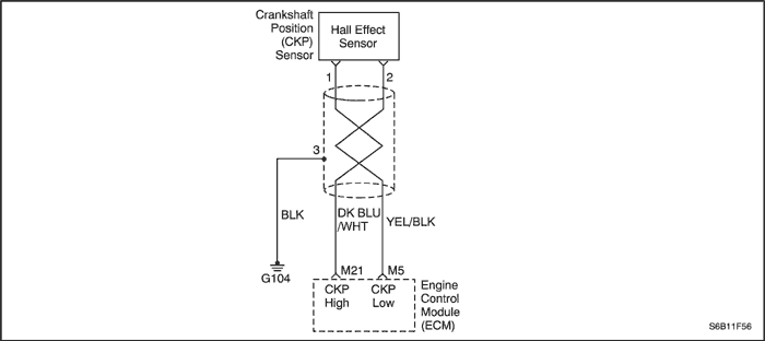
The 58X reference signal is produced by the Crankshaft Position (CKP) sensor. During one crankshaft revolution, 58 crankshaft pulses will be produced. The Engine Control Module (ECM) uses the 58X reference signal to calculate engine rpm and CKP. The ECM constantly monitors the number of pulses on the 58X reference circuit and compares them to the number of Camshaft Position (CMP) signal pulses being received. If the ECM does not receive any 58X reference pulses on the 58X reference circuit while cranking, Diagnostic Trouble Code (DTC) will set.
Conditions for Setting the DTC
- 58X reference pulse not seen during cranking.
- DTCs P0016 and P0340 are not set.
- Change in voltage drop is greater than 0.6 volts and change in Manifold Absolute Pressure (MAP) is greater than 1.2kPa for manual transaxle.
- Change in voltage drop is greater than 1.2 volts and change in Manifold Absolute Pressure (MAP) is greater than 0.8kPa for automatic transaxle.
- 58X reference pulse not seen for 8 seconds.
Action Taken When the DTC Sets
- The Malfunction Indicator Lamp (MIL) will illuminate.
- The ECM will record operating conditions at the time the diagnostic fails. This information will be stored in the Freeze Frame and Failure Records buffer.
- A history DTC is stored.
Conditions for Clearing the MIL/DTC
- The MIL will turn OFF after four consecutive ignition cycles in which the diagnostic runs without a fault.
- A history DTC will clear after 40 consecutive warm-up cycles have occurred without a fault.
- The DTC(s) can be cleared using the scan tool.
- Disconnecting the ECM battery feed for more than 10 seconds.
Diagnostic Aids
An intermittent may be caused by a poor connection, rubbed-through wire insulation or a wire broken inside the insulation. Check for:
- Poor connection - Inspect the ECM harness and connectors for improper mating, broken locks, improperly formed or damaged terminals, and poor terminal-towire connections.
- Damaged harness - Inspect the wiring harness for damage. If the harness appears to be OK, disconnect the ECM, turn the ignition ON and observe a voltmeter connected to the 58X reference circuit at the ECM harness connector while moving the connectors and the wiring harnesses related to the ECM. A change in voltage will indicate the location of the fault.
- Reviewing the Failure Records vehicle mileage since the diagnostic test last failed may help determine how often the condition that caused the DTC to be set occurs. This may assist in diagnosing the condition.
DTC P0335 - Crankshaft Position (CKP) Sensor Circuit
| Step | Action | Value(s) | Yes | No |
| 1 | Perform an On-Board Diagnostic (EOBD) System Check. Was the check performed? | - | Go to Step 2 | |
| 2 | - Turn the ignition OFF.
- Install a scan tool to the Data Link Connector (DLC).
- Start the engine.
- Operate the vehicle within the Freeze Frame conditions and Conditions for Setting the DTC as noted.
Is Diagnostic Trouble Code (DTC) P0335 set? | - | Go to Step 3 | Go to Step 10 |
| 3 | - Turn the ignition OFF.
- Disconnect the Crankshaft Position (CKP) sensor connector.
- Turn the ignition ON.
- Using a voltmeter, check the voltage between the CKP sensor wiring harness connector (Engine Control Module [ECM] side) terminal 1 and ground.
Does the voltage within the value specified? | 1.4 volts | Go to Step 4 | Go to Step 5 |
| 4 | Using a voltmeter, check the voltage between the CKP sensor wiring harness connector (ECM side) terminal 2 and ground. Does the voltage within the value specified? | 1.4 volts | Go to Step 6 | Go to Step 5 |
| 5 | - Turn the ignition OFF.
- Disconnect the ECM connector.
- Turn the ignition ON.
- Using a voltmeter, check the out put voltage of the ECM terminal M21 and M05.
Does the voltage within the value specified? | 11-14 volts | Go to Step 8 | Go to Step 9 |
| 6 | - Reconnect the CKP sensor.
- Using a voltmeter, back probe the ECM connector terminal M21 and M05.
- Observe the voltage while cranking the engine.
Does the voltage fluctuate between the specified value? | 1.3-1.6 volts | | Go to Step 7 |
| 7 | - Turn the ignition OFF.
- Replace the CKP sensor.
Is the repair complete? | - | Go to Step 10 | - |
| 8 | Check the CKP sensor high and low circuits for an open, short to ground or voltage and repair as needed. Is the repair complete? | - | Go to Step 10 | - |
| 9 | - Turn the ignition OFF.
- Replace the ECM.
Is the repair complete? | - | Go to Step 10 | - |
| 10 | - Using the scan tool, clear the DTCs.
- Start the engine and idle at normal operating temperature.
- Operate the vehicle within the conditions for setting this DTC as supported in the text.
Does the scan tool indicate that this diagnostic ran and passed? | - | Go to Step 11 | Go to Step 2 |
| 11 | Check if any additional DTCs are set. Are any DTCs displayed that have not been diagnosed? | - | Go to "Applicable DTC table" | System OK |
Diagnostic Trouble Code (DTC) P0336
Crankshaft Position (CKP) Sensor Performance
Circuit Description
The 58X reference signal is produced by the Crankshaft Position (CKP) sensor. During one crankshaft revolution, 58 crankshaft pulses will be produced. The Engine Control Module (ECM) uses the 58X reference signal to calculate engine rpm and CKP. The ECM constantly monitors the number of pulses on the 58X reference circuit and compares them to the number of Camshaft Position (CMP) signal pulses being received. If the ECM receives and incorrect number of pulses on the 58X reference circuit, Diagnostic Trouble Code (DTC) P0336 will set.
Conditions for Setting the DTC
- Engine is running.
- Extra or missing pulses detected between consecutive 58X reference pulses.
- Number of extra or missing teeth is greater than or equal to 2 per revolution.
- Above condition is detected in 10 of 100 crankshaft rotations.
Action Taken When the DTC Sets
- The Malfunction Indicator Lamp (MIL) will illuminate.
- The ECM will record operating conditions at the time the diagnostic fails. This information will be stored in the Freeze Frame and Failure Records buffer.
- A history DTC is stored.
Conditions for Clearing the MIL/DTC
- The MIL will turn OFF after four consecutive ignition cycles in which the diagnostic runs without a fault.
- A history DTC will clear after 40 consecutive warm-up cycles have occurred without a fault.
- The DTC(s) can be cleared using the scan tool.
- Disconnecting the ECM battery feed for more than 10 seconds.
Diagnostic Aids
An intermittent may be caused by a poor connection, rubbed-through wire insulation or a wire broken inside the insulation. Check for:
- Poor connection - Inspect the ECM harness and connectors for improper mating, broken locks, improperly formed or damaged terminals, and poor terminal-towire connections.
- Damaged harness - Inspect the wiring harness for damage. If the harness appears to be OK, disconnect the ECM, turn the ignition ON and observe a voltmeter connected to the 58X reference circuit at the ECM harness connector while moving the connectors and the wiring harnesses related to the ECM. A change in voltage will indicate the location of the fault.
- Reviewing the Failure Records vehicle mileage since the diagnostic test last failed may help determine how often the condition that caused the DTC to be set occurs. This may assist in diagnosing the condition.
DTC P0336 - Crankshaft Position (CKP) Sensor Performance
| Step | Action | Value(s) | Yes | No |
| 1 | Perform an On-Board Diagnostic (EOBD) System Check. Was the check performed? | - | Go to Step 2 | |
| 2 | Attempt to start the engine. Does the engine start? | - | Go to Step 3 | |
| 3 | - Turn the ignition OFF.
- Install a scan tool to the Data Link Connector (DLC).
- Turn the ignition ON, with the engine OFF.
- Review and record Failure Records information.
- Clear the Diagnostic Trouble Codes (DTCs).
- Start the engine and idle for 1 minute.
Is DTC P0336 set? | - | Go to Step 4 | |
| 4 | - Turn the ignition OFF.
- Disconnect the Engine Control Module (ECM) connector and Crankshaft Position (CKP) sensor.
- Check for an open or short to ground in the 58X reference circuit between CKP sensor connector and the ECM harness connector.
Is a problem found? | - | Go to Step 5 | Go to Step 6 |
| 5 | Repair an open or short to ground in the 58X reference circuit between the CKP sensor connector and the ECM harness connector. Is the repair complete? | - | Go to Step 11 | - |
| 6 | Reconnect the ECM and CKP sensor. Connect a voltmeter to measure the voltage at terminal M21 of the ECM connector. Observe the voltage while cranking the engine. Is the voltage near the specified value? | 1.6 v | Go to Step 9 | Go to Step 7 |
| 7 | Check the connections at CKP sensor and repair or replace the terminals. Is the repair complete? | - | Go to Step 11 | Go to Step 8 |
| 8 | - Turn the ignition OFF.
- Replace the CKP sensor.
Is the repair complete? | - | Go to Step 11 | - |
| 9 | Check the connections at ECM and repair or replace the terminals. Is the repair complete? | - | Go to Step 11 | Go to Step 10 |
| 10 | - Turn the ignition OFF.
- Replace the ECM.
Is the repair complete? | - | Go to Step 11 | - |
| 11 | - Using the scan tool, clear the DTCs.
- Start the engine and idle at normal operating temperature.
- Operate the vehicle within the conditions for setting this DTC as supported in the text.
Does the scan tool indicate that this diagnostic ran and passed? | - | Go to Step 12 | Go to Step 2 |
| 12 | Check if any additional DTCs are set. Are any DTCs displayed that have not been diagnosed? | - | Go to applicable DTC table | System OK |
 | |  | |
| © Copyright Chevrolet Europe. All rights reserved |