Diagnostic Trouble Code (DTC) P0340
Camshaft Position (CMP) Sensor Circuit
System Description
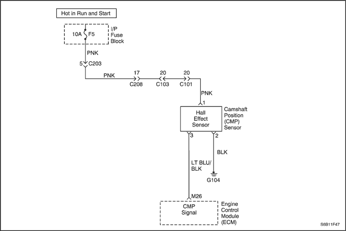
The Camshaft Position (CMP) Sensor is used to correlate crankshaft to camshaft position so that the Engine Control Module (ECM) can determine which cylinder is ready to be fueled by the injector. The CMP is also used to determine which cylinder is misfiring when a misfire is present. When the ECM cannot use the information from the CMP sensor, a Diagnostic Trouble Code (DTC) is set, and the ECM will fuel the engine using the Alternating Synchronous Double Fire (ASDF) method.
Conditions for Setting the DTC
- CMP Sensor pulse is not detected at the correct interval every 4 cylinders.
- Engine is running.
Action Taken When the DTC Sets
- The Malfunction Indicator Lamp (MIL) will illuminate.
- The ECM will record operating conditions at the time the diagnostic fails. This information will be stored in the Freeze Frame and Failure Records buffers.
- A history DTC is stored.
Conditions for Clearing the MIL/DTC
- The MIL will turn off after four consecutive ignition cycles in which the diagnostic runs without a fault.
- A history DTC will clear after 40 consecutive warm-up cycles without a fault.
- DTC(s) can be cleared by using the scan tool.
- Disconnecting the ECM battery feed for more than 10 seconds.
Diagnostic Aids
An intermittent problem may be caused by a poor connection, rubbed-through wire insulation, or a wire that is broken inside the insulation.
Any circuitry, that is suspected as causing the complaint, should be thoroughly checked for the following conditions:
- Backed-out terminals
- Improper mating
- Broken locks
- Improperly formed
- Damaged terminals
- Poor terminal-to-wire connection
- Physical damage to the wiring harness
Test Description
Number(s) below refer to the step number(s) on the Diagnostic Table.
- The On-Board Diagnostic (EOBD) System Check prompts the technician to complete some basic checks and to store the freeze frame and failure records data on the scan tool if applicable. This creates an electronic copy of the data taken when the malfunction occurred. The information is then stored on the scan tool for later reference.
- This step determines if a DTC is the result of a hard failure or an intermittent condition.
- Determines if voltage is available to the CMP.
- This step checks for a voltage supplied by the ECM to the CMP.
- The replacement ECM must be reprogrammed. Refer to the latest Techline procedure for ECM reprogramming.
DTC P0340 - Camshaft Position (CMP) Sensor Circuit
| Step | Action | Value(s) | Yes | No |
| 1 | Perform an On-Board Diagnostic (EOBD) System Check. Was the check performed? | - | Go to Step 2 | |
| 2 | - Turn the ignition OFF.
- Install a scan tool to the Data Link Connector (DLC).
- Idle the engine.
Is the Camshaft Position (CMP) Active Count incrementing? | - | Go to Step 3 | Go to Step 4 |
| 3 | - Turn the ignition ON.
- Review the Freeze Frame data and note the parameters.
- Start the engine and operate the vehicle within the Freeze Frame Conditions and Conditions for Setting the DTC as noted.
Is the CMP Active Counter incrementing? | - | Go to Step 13 | Go to Step 4 |
| 4 | - Turn the ignition OFF.
- Disconnect the CMP sensor connector.
- Turn the ignition ON.
- With a test light connected to ground, probe the CMP sensor harness connector, terminal 1.
Does the test light illuminate? | - | Go to Step 5 | Go to Step 6 |
| 5 | With a test light connected to B+, probe the CMP sensor harness connector, terminal 2. Does the test light illuminate? | - | Go to Step 7 | Go to Step 8 |
| 6 | Check for a poor connection or open in the CMP sensor B+ feed circuit and repair as necessary. Is the repair complete? | - | Go to Step 13 | |
| 7 | Using a Digital Voltmeter (DVM), check the voltage between the CMP sensor harness connector, terminal 3 and ground. Does the DVM display near the specified values? | 5 V | Go to Step 11 | Go to Step 9 |
| 8 | Check for a poor connection or open in the CMP sensor ground circuit and repair as necessary. Is the repair complete? | - | Go to Step 13 | - |
| 9 | - Turn the ignition OFF.
- Disconnect the engine Control Module (ECM) connector.
- Check for the CMP signal circuit for an open or short to round or short to B+, and repair as needed.
Is the repair complete? | - | Go to Step 13 | Go to Step 10 |
| 10 | Check the CMP signal circuit for an open or short to ground and repair as needed. Is the repair complete? | - | Go to Step 13 | Go to Step 12 |
| 11 | - Turn the ignition OFF.
- Replace the CMP sensor.
Is the repair complete? | - | Go to Step 13 | - |
| 12 | - Turn the ignition OFF.
- Replace the ECM.
Is the repair complete? | - | Go to Step 13 | - |
| 13 | - Using the scan tool, clear the DTCs.
- Start the engine and idle at normal operating temperature.
- Operate the vehicle within the conditions for setting this DTC as supported in the text.
Does the scan tool indicate that this diagnostic ran and passed? | - | Go to Step 14 | Go to Step 2 |
| 14 | Check if any additional DTCs are set. Are any DTCs displayed that have not been diagnosed? | - | Go to "Applicable DTC table" | System OK |
Diagnostic Trouble Code (DTC) P0351
Ignition Coil 1 and 4 Control Circuit
Circuit Description
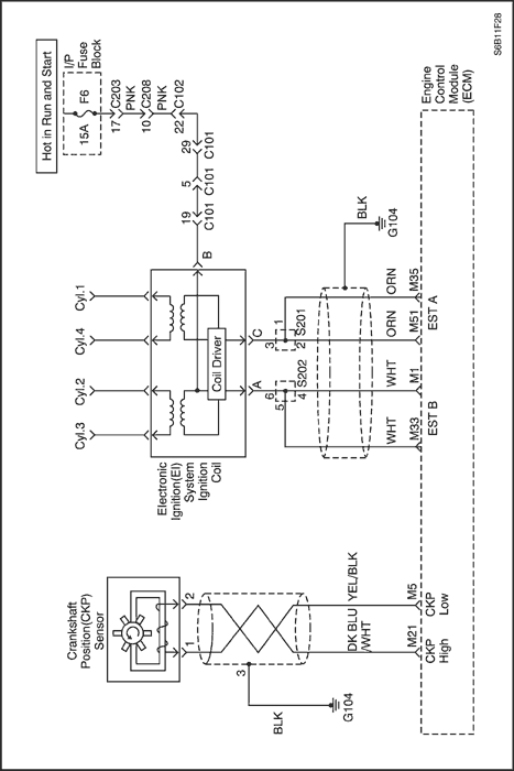
The Engine Control Module (ECM) provides a ground for the electronic spark timing A circuit. When the ECM removes the ground path of the ignition primary coil, the magnetic field produced by the coil collapses. The collapsing magnetic field produces a voltage in the secondary coil which fires the spark plug.
The circuit between the ECM and the electronic ignition system ignition coil is monitored for an open circuit, short to voltage, and short to ground. When the ECM detects a problem in the electronic spark timing A circuit, it will set Diagnostic Trouble Code (DTC).
Conditions for Setting the DTC
- Monitor fault feedback signal.
- Ignition ON.
- Fault flag increments fail count.
- Must receive more than 20 failures within 40 test cycles.
Action Taken When the DTC Sets
- The Malfunction Indicator Lamp (MIL) will illuminate.
- The ECM will record operating conditions at the time the diagnostic fails. This information will be stored in the Freeze Frame and Failure Records buffers.
- Low speed coolant fan turns on.
- A history DTC is stored.
Conditions for Clearing the MIL/DTC
- The MIL will turn off after four consecutive ignition cycles in which the diagnostic runs without a fault.
- A history DTC will clear after 40 consecutive warm-up cycles without a fault.
- DTC(s) can be cleared by using the scan tool.
- Disconnecting the ECM battery feed for more than 10 seconds.
Diagnostic Aids
An intermittent may be caused by a poor connection, rubbed-through wire insulation or a wire broken inside the insulation. Check for:
- Poor connection - Inspect the ECM harness and connectors for improper mating, broken locks, improperly formed or damaged terminals, and poor terminal-towire connection.
- Damaged harness - Inspect the wiring harness for damage. If the harness appears to be OK, disconnect the ECM, turn the ignition on, and observe a voltmeter connected to the 58X reference circuit at the ECM harness connector while moving connectors and wiring harnesses related to the ECM. A change in voltage will indicate the location of the fault.
Reviewing the Failure Records vehicle mileage since the diagnostic test last failed may help determine how often the condition that caused the DTC to be set occurs. This may assist in diagnosing the condition.
DTC P0351 - Ignition Coil 1 and 4 Control Circuit
| Step | Action | Value(s) | Yes | No |
| 1 | Perform an On-Board Diagnostic (EOBD) System Check. Was the check performed? | - | Go to Step 2 | |
| 2 | Check for a faulty connection or damaged terminal C at the Electronic Ignition (EI) system ignition coil and repair as needed. Is the repair complete? | - | Go to Step 8 | Go to Step 3 |
| 3 | Check for a faulty connection or damaged terminal M51/M35 at the Engine Control Module (ECM) and repair as needed. Is the repair complete? | - | Go to Step 8 | Go to Step 4 |
| 4 | - Ignition OFF.
- Disconnect the ECM connector.
- Check the ignition control circuit for a short to ground and repair as needed.
Is the repair complete? | - | Go to Step 8 | Go to Step 5 |
| 5 | Check the ignition control circuit for a short to voltage and repair as necessary. Is the repair complete? | - | Go to Step 8 | Go to Step 6 |
| 6 | Check an open ignition control circuit and repair as needed. Is the repair complete? | - | Go to Step 8 | Go to Step 7 |
| 7 | - Turn the ignition OFF.
- Replace the ECM.
Is the repair complete? | - | Go to Step 8 | - |
| 8 | - Using the scan tool, clear the Diagnostic Trouble Codes (DTCs).
- Start the engine and idle at normal operating temperature.
- Operate the vehicle within the conditions for setting this DTC as supported in the text.
Does the scan tool indicate that this diagnostic ran and passed? | - | Go to Step 9 | Go to Step 2 |
| 9 | Check if any additional DTCs are set. Are any DTCs displayed that have not been diagnosed? | - | Go to applicable DTC table | System OK |
Diagnostic Trouble Code (DTC) P0352
Ignition Coil 2 and 3 Control Circuit
Circuit Description
The Engine Control Module (ECM) provides a ground for the electronic spark timing A circuit. When the ECM removes the ground path of the ignition primary coil, the magnetic field produced by the coil collapses. The collapsing magnetic field produces a voltage in the secondary coil which fires the spark plug.
The circuit between the ECM and the electronic ignition system ignition coil is monitored for an open circuit, short to voltage, and short to ground. When the ECM detects a problem in the electronic spark timing A circuit, it will set Diagnostic Trouble Code (DTC).
Conditions for Setting the DTC
- Monitor fault feedback signal.
- Ignition ON.
- Fault flag increments fail count.
- Must receive more than 20 failures within 40 test cycles.
Action Taken When the DTC Sets
- The Malfunction Indicator Lamp (MIL) will illuminate.
- The ECM will record operating conditions at the time the diagnostic fails. This information will be stored in the Freeze Frame and Failure Records buffers.
- Low speed coolant fan turns on.
- A history DTC is stored.
Conditions for Clearing the MIL/DTC
- The MIL will turn off after four consecutive ignition cycles in which the diagnostic runs without a fault.
- A history DTC will clear after 40 consecutive warm-up cycles without a fault.
- DTC(s) can be cleared by using the scan tool.
- Disconnecting the ECM battery feed for more than 10 seconds.
Diagnostic Aids
An intermittent may be caused by a poor connection, rubbed-through wire insulation or a wire broken inside the insulation. Check for:
- Poor connection - Inspect the ECM harness and connectors for improper mating, broken locks, improperly formed or damaged terminals, and poor terminal-towire connection.
- Damaged harness - Inspect the wiring harness for damage. If the harness appears to be OK, disconnect the ECM, turn the ignition on, and observe a voltmeter connected to the 58X reference circuit at the ECM harness connector while moving connectors and wiring harnesses related to the ECM. A change in voltage will indicate the location of the fault.
Reviewing the Failure Records vehicle mileage since the diagnostic test last failed may help determine how often the condition that caused the DTC to be set occurs. This may assist in diagnosing the condition.
DTC P0352 - Ignition Coil 2 and 3 Control Circuit
| Step | Action | Value(s) | Yes | No |
| 1 | Perform an On-Board Diagnostic (EOBD) System Check. Was the check performed? | - | Go to Step 2 | |
| 2 | Check for a faulty connection or damaged terminal A at the Electronic Ignition (EI) system ignition coil and repair as needed. Is the repair complete? | - | Go to Step 8 | Go to Step 3 |
| 3 | Check for a faulty connection or damaged terminal M33/M1 at the Engine Control Module (ECM) and repair as needed. Is the repair complete? | - | Go to Step 8 | Go to Step 4 |
| 4 | - Turn the ignition OFF.
- Disconnect the ECM connector.
- Check the ignition control circuit for a short to ground and repair as needed.
Is the repair complete? | - | Go to Step 8 | Go to Step 5 |
| 5 | Check the ignition control circuit for a short to voltage and repair as needed. Is the repair complete? | - | Go to Step 8 | Go to Step 6 |
| 6 | Check for an open in the ignition control circuit and repair as needed. Is the repair complete? | - | Go to Step 8 | Go to Step 7 |
| 7 | - Turn the ignition OFF.
- Replace the ECM.
Is the repair complete? | - | Go to Step 8 | - |
| 8 | - Using the scan tool, clear the Diagnostic Trouble Codes (DTCs).
- Start the engine and idle at normal operating temperature.
- Operate the vehicle within the conditions for setting this DTC as supported in the text.
Does the scan tool indicate that this diagnostic ran and passed? | - | Go to Step 9 | Go to Step 2 |
| 9 | Check if any additional DTCs are set. Are any DTCs displayed that have not been diagnosed? | - | Go to applicable DTC table | System OK |
 | |  | |
| © Copyright Chevrolet Europe. All rights reserved |