Diagnostic Trouble Code (DTC) P0562
System Voltage Too Low
Circuit Description
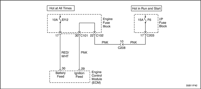
The engine control module (ECM) monitors the ignition voltage on the ignition feed circuit to terminal 29 at the ECM. A system voltage Diagnostic Trouble Code (DTC) will set whenever the voltage is below a calibrated value.
Conditions for Running the DTC
Conditions for Setting the DTC
- The system voltage is less than 4.969V or higher than 17.958V during 7.65 seconds.
Action Taken When the DTC Sets
- The Malfunction Indicator Lamp (MIL) will not illuminate.
- The ECM will record operating conditions at the time the diagnostic fails. This information will be stored Failure Records buffers.
Conditions for Clearing the MIL/DTC
- A history DTC will clear after 40 warm-up cycles without a fault.
- DTC(s) can be cleared by using the scan tool.
Diagnostic Aids
An Intermittent problem may be caused by a poor connection, rubbed through wire insulation, or wire that is broken inside the insulation.
Any circuitry, that is suspected as causing the complaint, should be thoroughly checked for the following conditions.
- Backed-out terminals
- Improper mating
- Broken locks
- Improperly formed
- Damaged terminals
- Poor terminal to wiring connections
- Physical damage to the wiring harness
DTC P0562 - System Voltage Too Low
| Step | Action | Value(s) | Yes | No |
| 1 | Perform the Diagnostic System Check. Is the system check complete? | - | Go to Step 2 | |
| 2 | - Install a scan tool and clear the Diagnostic Trouble Codes (DTCs).
- Start the engine and raise the engine speed to 1400 rpm.
- Load the electrical system by turning on the headlights, high blower motor, etc.
Is the ignition voltage less than the specified value? | 10 V | Go to Step 3 | Go to Step 8 |
| 3 | - Maintain the engine running at 1400 rpm.
- Using a digital voltmeter(DVM), measure the battery voltage at the battery.
Is the battery voltage less than the specified value? | 12 V | Go to Step 4 | |
| 4 | - Turn the ignition switch to LOCK.
- Disconnect the engine control module(ECM) connector at the ECM.
- Turn the ignition switch to ON with the engine OFF.
- Using a DVM, measure the ignition voltage at the ignition feed circuit, terminal 29.
Is the ignition voltage less than the specified value? | 10 V | Go to Step 5 | Go to Step 6 |
| 5 | Check for a malfunctioning connection at the ECM harness terminals and repair as necessary. Is a repair necessary? | - | Go to Step 8 | Go to Step 7 |
| 6 | Repair the poor connection in the ignition feed circuit. Is the repair complete? | - | Go to Step 8 | - |
| 7 | Replace the ECM. Is the replacement complete? | - | Go to Step 8 | - |
| 8 | - Using the scan tool, clear the DTCs.
- Start the engine and idle at normal operating temperature.
- Operate the vehicle within the Conditions for setting this DTC as specified in the supporting text.
Does the scan tool indicate that this diagnostic has run and passed? | - | Go to Step 9 | Go to Step 2 |
| 9 | Check if any additional DTCs are set. Are any DTCs displayed that have not been diagnosed? | - | Go to applicable DTC table | System OK |
Diagnostic Trouble Code (DTC) P0563
System Voltage Too High
Circuit Description
The engine control module (ECM) monitors the ignition voltage on the ignition feed circuit to terminal 29 at the ECM. A system voltage Diagnostic Trouble Code (DTC) will set whenever the voltage is above a calibrated value.
Conditions for Running the DTC
Conditions for Setting the DTC
- The system relay voltage is greater than 7.9V at the end of power latch.
Action Taken When the DTC Sets
- The Malfunction Indicator Lamp (MIL) will not illuminate.
- The ECM will record operating conditions at the time the diagnostic fails. This information will be stored Failure Records buffers.
Conditions for Clearing the MIL/DTC
- A history DTC will clear after 40 warm-up cycles without a fault.
- DTC(s) can be cleared by using the scan tool.
Diagnostic Aids
An Intermittent problem may be caused by a poor connection, rubbed through wire insulation, or wire that is broken inside the insulation.
Any circuitry, that is suspected as causing the complaint, should be thoroughly checked for the following conditions.
- Backed-out terminals
- Improper mating
- Broken locks
- Improperly formed
- Damaged terminals
- Poor terminal to wiring connections
- Physical damage to the wiring harness
DTC P0563 - System Voltage Too High
| Step | Action | Value(s) | Yes | No |
| 1 | Perform the Diagnostic System Check. Is the system check complete? | - | Go to Step 2 | |
| 2 | - Install a scan tool and clear the Diagnostic Trouble Codes (DTCs).
- Start the engine and raise the engine speed to 1400 rpm.
- Load the electrical system by turning on the headlights, high blower motor, etc.
Is the ignition voltage greater than the specified value? | 10 V | Go to Step 3 | Go to Step 8 |
| 3 | - Maintain the engine running at 1400 rpm.
- Using a digital voltmeter(DVM), measure the battery voltage at the battery.
Is the battery voltage greater than the specified value? | 12 V | Go to Step 4 | |
| 4 | - Turn the ignition switch to LOCK.
- Disconnect the engine control module(ECM) connector at the ECM.
- Turn the ignition switch to ON with the engine OFF.
- Using a DVM, measure the ignition voltage at the ignition feed circuit, terminal 29.
Is the ignition voltage greater than the specified value? | 10 V | Go to Step 5 | Go to Step 6 |
| 5 | Check for a malfunctioning connection at the ECM harness terminals and repair as necessary. Is a repair necessary? | - | Go to Step 8 | Go to Step 7 |
| 6 | Repair the poor connection in the ignition feed circuit. Is the repair complete? | - | Go to Step 8 | - |
| 7 | Replace the ECM. Is the replacement complete? | - | Go to Step 8 | - |
| 8 | - Using the scan tool, clear the DTCs.
- Start the engine and idle at normal operating temperature.
- Operate the vehicle within the Conditions for setting this DTC as specified in the supporting text.
Does the scan tool indicate that this diagnostic has run and passed? | - | Go to Step 9 | Go to Step 2 |
| 9 | Check if any additional DTCs are set. Are any DTCs displayed that have not been diagnosed? | - | Go to applicable DTC table | System OK |
Diagnostic Trouble Code (DTC)
P0601 - Engine Control Module Checksum Error
P0604 - Engine Control Module RAM Error
P0605 - Engine Control Module Write Error
Circuit Description
The engine control module (ECM) is the control center of the fuel injection system. It constantly looks at the information from various sensors, and controls the systems that after vehicle performance. The ECM also performs the diagnostic function of the system. It can recognize operational problems, alert the driver through the Malfunction Indicator Lamp (MIL), and store a Diagnostic Trouble Code (DTC) or DTCs which identify the problem areas to aid the technician in making repairs. An electrically erasable programmable read only memory (EEPROM) is used to house the program information and the calibrations required for engine, transaxle, transaxle diagnostics operation. The ECM uses a value called a checksum for error detection of the software. The checksum is a value that is equal to all the numbers in the software added together. The ECM adds all the values in the software and if that value does not equal the checksum value, a checksum error is indicated.
Conditions for Running the DTC
Conditions for Setting the DTC
(P0601)
- The ECM detects incorrect checksum.
(P0604)
- The ECM detects an internal or external Random Access Memory (RAM) error.
(P0605)
- The ECM detects a INMVY write error.
Action Taken When the DTC Sets
- The Malfunction Indicator Lamp (MIL) will illuminate.
- The ECM will record operating conditions at the time the diagnostic fails. The information will be stored in the Freeze Frame and Failure Records buffers.
- A history DTC is stored.
Conditions for Clearing the MIL/DTC
- The MIL will turn at the end of three consecutive validation cycles in which the diagnostic runs without a fault.
- A history DTC will clear after 40 warm-up cycles without a fault.
- DTC(s) can be cleared by using the scan tool.
DTC P0601 - Engine Control Module Checksum Error
DTC P0604 - Engine Control Module RAM Error
DTC P0605 - Engine Control Module Write Error
| Step | Action | Value(s) | Yes | No |
| 1 | Perform the Diagnostic System Check. Is the system check complete? | - | Go to Step 2 | |
| 2 | Replace the engine control module(ECM). Is the replacement complete? | - | Go to Step 3 | - |
| 3 | - Using the scan tool, clear the DTCs.
- Start the engine and idle at normal operating temperature.
- Operate the vehicle within the conditions for setting this DTC ad specified in the supporting text.
Does the scan tool indicate that this diagnostic has run and passed? | - | Go to Step 4 | Go to Step 2 |
| 4 | Check if any additional DTCs are set. Are any DTCs displayed that have not been diagnosed? | - | Go to applicable DTC table | System OK |
Diagnostic Trouble Code (DTC) P0628
Fuel Pump Relay Low Voltage
Circuit Description
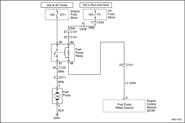
When the ignition switch is turned ON, the ECM will activate the fuel pump relay and run the in-tank fuel pump.
The fuel pump will operate as long as the engine is cranking or running and the ECM is receiving ignition reference pulses.
Conditions for Running the DTC
Conditions for Setting the DTC
- The ECM detects a continuous short to ground or line break in either the fuel pump control circuit or the fuel pump.
Action Taken When the DTC Sets
- The Malfunction Indicator Lamp (MIL) will not illuminate.
- The ECM will record operating conditions at the time the diagnostic fails. This information will be stored in the Freeze Frame and Records buffers.
Conditions for Clearing the MIL/DTC
- A history DTC will clear after 40 warm up cycles without a fault.
- DTC(s) can be cleared by using the scan tool.
Diagnostic Aids
An Intermittent problem may be caused by a poor connection, rubbed through wire insulation, or wire that is broken inside the insulation.
Any circuitry, that is suspected as causing the complaint, should be thoroughly checked for the following conditions.
- Backed-out terminals
- Improper mating
- Broken locks
- Improperly formed
- Damaged terminals
- Poor terminals to wire connection
- Physical damage to the wiring harness
DTC P0628 - Fuel Pump Relay Low Voltage
| Step | Action | Value(s) | Yes | No |
| 1 | Perform the Diagnostic System Check. Is the system check complete? | - | Go to Step 2 | |
| 2 | - Turn the ignition switch to LOCK for 10 seconds.
- Turn the ignition switch to ON.
- Listen for in-tank fuel pump operation.
Does the fuel pump operate? | 2 seconds | | Go to Step 3 |
| 3 | - Turn the ignition switch to ON.
- Disconnect the fuel pump relay.
- Connect a test light between the fuel pump relay connector terminal 86 and ground.
- Turn the ignition switch to ON.
Is the test light ON? | - | Go to Step 4 | Go to Step 10 |
| 4 | - Turn the ignition switch to ON.
- Disconnect the fuel pump relay.
- Connect a test light between the fuel pump relay connector terminal 85 and B+.
- Turn the ignition switch to ON.
Is the test light ON? | - | Go to Step 5 | Go to Step 9 |
| 5 | - Turn the ignition switch to LOCK.
- Connect a test light between the fuel pump relay connector terminal 30 and ground.
Is the test light ON? | - | Go to Step 6 | Go to Step 8 |
| 6 | Check for short to ground in the wire between the fuel pump relay connector terminal 87 and fuel pump connector. Is the problem found? | - | Go to Step 7 | Go to Step 8 |
| 7 | - Repair the wire between the fuel pump relay connector terminal 87 and fuel pump connector terminal 3.
- Install the fuel pump relay.
- Turn the engine OFF for 10 seconds.
- Clear any DTCs from ECM.
- Turn the ignition switch to ON.
Does the fuel pump operate? | 2 seconds | Go to Step 14 | - |
| 8 | - Replace the fuel pump relay.
- Turn the ignition OFF for 10 seconds.
- Clear any DTCs from ECM.
- Turn the ignition switch to ON.
Does the fuel pump operate? | 2 seconds | Go to Step 14 | Go to Step 9 |
| 9 | Check for a short to ground wire between the fuel pump relay connector terminal 85 and the ignition after key ON(IGN 1). Is the problem found? | - | Go to Step 11 | Go to Step 10 |
| 10 | Check for a short to ground wire between the fuel pump relay connector terminal 86 and the ECM connector terminal 6. Is the problem found? | - | Go to Step 12 | Go to Step 13 |
| 11 | - Repair the wire between the fuel pump relay connector terminal 85 and the ignition key ON (IGN1).
- Install the fuel pump relay.
- Turn the ignition OFF for 10 seconds.
- Clear any DTCs from ECM.
- Turn the ignition switch to ON.
Does the fuel pump operate? | 2 seconds | System OK | Go to Step 13 |
| 12 | - Repair the wire between the fuel pump relay connector terminal 86 and the ECM connector terminal 6.
- Install the fuel pump relay.
- Turn the ignition OFF for 10 seconds.
- Clear any DTCs from ECM.
- Turn the ignition switch to ON.
Does the fuel pump operate? | 2 seconds | System OK | Go to Step 13 |
| 13 | - Replace the ECM.
- Turn the ignition OFF for 10 seconds.
- Clear any DTCs from ECM.
- Turn the ignition switch to ON.
Does the fuel pump operate? | 2 seconds | System OK | Go to Step 14 |
| 14 | - Using the scan tool, clear the DTCs.
- Start the engine and idle at normal operating temperature.
- Operate the vehicle within the conditions for setting this DTC ad specified in the supporting text.
Does the scan tool indicate that this diagnostic has run and passed? | - | Go to Step 15 | Go to Step 2 |
| 15 | Check if any additional DTCs are set. Are any DTCs displayed that have not been diagnosed? | - | Go to applicable DTC table | System OK |
Diagnostic Trouble Code (DTC) P0629
Fuel Pump Relay High Voltage
Circuit Description
When the ignition switch is turned ON, the ECM will activate the fuel pump relay and run the in-tank fuel pump.
The fuel pump will operate as long as the engine is cranking or running and the ECM is receiving ignition reference pulses.
Conditions for Running the DTC
Conditions for Setting the DTC
- The ECM detects a continuous short to battery in either the fuel pump control circuit or the fuel pump.
Action Taken When the DTC Sets
- The Malfunction Indicator Lamp (MIL) will not illuminate.
- The ECM will record operating conditions at the time the diagnostic fails. This information will be stored in the Freeze Frame and Records buffers.
Conditions for Clearing the MIL/DTC
- A history DTC will clear after 40 warm up cycles without a fault.
- DTC(s) can be cleared by using the scan tool.
Diagnostic Aids
An Intermittent problem may be caused by a poor connection, rubbed through wire insulation, or wire that is broken inside the insulation.
Any circuitry, that is suspected as causing the complaint, should be thoroughly checked for the following conditions.
- Backed-out terminals
- Improper mating
- Broken locks
- Improperly formed
- Damaged terminals
- Poor terminals to wire connection
- Physical damage to the wiring harness
DTC P0629 - Fuel Pump Relay High Voltage
| Step | Action | Value(s) | Yes | No |
| 1 | Perform the Diagnostic System Check. Is the system check complete? | - | Go to Step 2 | |
| 2 | - Turn the ignition switch to LOCK for 10 seconds.
- Turn the ignition switch to ON.
- Listen for in-tank fuel pump operation.
Does the fuel pump operate? | 2 seconds | | Go to Step 3 |
| 3 | Check for short to battery voltage or low voltage in the wire between the fuel pump relay connector terminal 87 and fuel pump connector 3. Is the problem found? | - | Go to Step 7 | Go to Step 5 |
| 4 | - Repair the wire between the fuel pump relay connector terminal 87 and fuel pump connector terminal 3.
- Install the fuel pump relay.
- Turn the engine OFF for 10 seconds.
- Clear any DTCs from ECM.
- Turn the ignition switch to ON.
Does the fuel pump operate? | 2 seconds | Go to Step 11 | - |
| 5 | - Replace the fuel pump relay.
- Turn the ignition OFF for 10 seconds.
- Clear any DTCs from ECM.
- Turn the ignition switch to ON.
Does the fuel pump operate? | 2 seconds | Go to Step 11 | Go to Step 6 |
| 6 | Check for short to battery voltage wire between the fuel pump relay connector terminal 85 and the ignition after key ON(IGN 1). Is the problem found? | - | Go to Step 8 | Go to Step 7 |
| 7 | Check for an open wire between the fuel pump relay connector terminal 86 and the ECM connector terminal 6. Is the problem found? | - | Go to Step 9 | Go to Step 10 |
| 8 | - Repair the wire between the fuel pump relay connector terminal 85 and the ignition key ON (IGN1).
- Install the fuel pump relay.
- Turn the ignition OFF for 10 seconds.
- Clear any DTCs from ECM.
- Turn the ignition switch to ON.
Does the fuel pump operate? | 2 seconds | System OK | Go to Step 10 |
| 9 | - Repair the wire between the fuel pump relay connector terminal 86 and the ECM connector terminal 6.
- Install the fuel pump relay.
- Turn the ignition OFF for 10 seconds.
- Clear any DTCs from ECM.
- Turn the ignition switch to ON.
Does the fuel pump operate? | 2 seconds | System OK | Go to Step 10 |
| 10 | - Replace the ECM.
- Turn the ignition OFF for 10 seconds.
- Clear any DTCs from ECM.
- Turn the ignition switch to ON.
Does the fuel pump operate? | 2 seconds | System OK | Go to Step 11 |
| 11 | - Using the scan tool, clear the DTCs.
- Start the engine and idle at normal operating temperature.
- Operate the vehicle within the conditions for setting this DTC ad specified in the supporting text.
Does the scan tool indicate that this diagnostic has run and passed? | - | Go to Step 12 | Go to Step 2 |
| 12 | Check if any additional DTCs are set. Are any DTCs displayed that have not been diagnosed? | - | Go to applicable DTC table | System OK |


Diagnostic Trouble Code (DTC) P0650
Malfunction Indicator Lamp (MIL) Low Voltage
Circuit Description
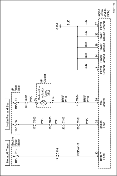
When the ignition switch to ON, the Malfunction Indicator Lamp (MIL) is ON steady.
When the engine cranking, the Malfunction Indicator Lamp (MIL) is OFF after one flashing time.
If a system have some difficulties, the Malfunction Indicator Lamp (MIL) is ON.
Conditions for Running the DTC
Conditions for Setting the DTC
- The ECM detects a continuous short to ground or an open in the signal circuit.
Action Taken When the DTC Sets
- The Malfunction Indicator Lamp (MIL) will illuminate.
- The ECM will record operating conditions at the time the diagnostic fails. The information will be stored in the Freeze Frame and Failure Records buffers.
- A history DTC is stored.
Conditions for Clearing the MIL/DTC
- The MIL will turn at the end of three consecutive validation cycles in which the diagnostic runs without a fault.
- A history DTC will clear after 40 warm-up cycles without a fault.
- DTC(s) can be cleared by using the scan tool.
Diagnostic Aids
An Intermittent problem may be caused by a poor connection, rubbed through wire insulation, or wire that is broken inside the insulation.
Any circuitry, that is suspected as causing the complaint, should be thoroughly checked for the following conditions.
- Backed-out terminals
- Improper mating
- Broken locks
- Improperly formed
- Damaged terminals
- Poor terminals to wire connection
- Physical damage to the wiring harness
DTC P0650 - Malfunction Indicator Lamp (MIL) Low Voltage
| Step | Action | Value(s) | Yes | No |
| 1 | Perform the Diagnostic System Check. Is the system check complete? | - | Go to Step 2 | |
| 2 | - Turn the ignition switch to LOCK.
- Disconnect the cluster wiring connector.
- With the test light, connected to ground, probe the ignition feed circuit, at terminal A5 in the cluster harness connector.
Does the resistance within the specified value? | 0Ω | Go to Step 3 | Go to Step 6 |
| 3 | - Turn the ignition switch to LOCK.
- With the test light, connected to ground, probe the MIL control circuit, at ECM wiring connector terminal 39.
Does the test light illuminate? | - | Go to Step 4 | - |
| 4 | - Turn the ignition switch to LOCK.
- Replace the cluster.
Is the replacement complete? | - | Go to Step 6 | - |
| 5 | Repair a short to ground or open between the ECM wiring connector terminal 39 and cluster wiring connector terminal A14. Is the repair complete? | - | Go to Step 6 | - |
| 6 | - Using the scan tool, clear the Diagnostic Trouble Codes(DTCs).
- Start the engine and idle at normal operating temperature.
- Operate the vehicle within the conditions for setting this DTC as specified in the supporting text.
Does the scan tool indicate that this diagnostic has run and passed? | - | Go to Step 7 | Go to Step 2 |
| 7 | Check if any additional DTCs are set. Are any DTCs displayed that have not been diagnosed? | - | Go to applicable DTC table | System OK |
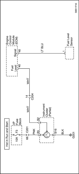
Diagnostic Trouble Code (DTC) P0656
Fuel Level Output Circuit Malfunction
Circuit Description
The engine control module (ECM) creates the fuel gage output signal by pulsing the circuit to ground. The ECM monitors the voltage on the fuel gage output circuit. If the ECM determines that the voltage is out of the normal operating range, a DTC sets.
Conditions for Running the DTC
Conditions for Setting the DTC
- A short to ground, a short to battery, or an open in the fuel tank level output circuit exists.
Action Taken When the DTC Sets
- The Malfunction Indicator Lamp (MIL) will not illuminate.
- The ECM will record operating conditions at the time the diagnostic fails. This information will be stored in the Freeze Frame and Records buffers.
Conditions for Clearing the MIL/DTC
- A history DTC will clear after 40 warm up cycles without a fault.
- DTC(s) can be cleared by using the scan tool.
Diagnostic Aids
Inspect harness connectors for backed-out terminal, improper mating, broken locks, improperly formed or damaged terminals, and poor terminal-to-wire connection.
Inspect the wiring harness for damage.
A stuck Fuel Level Sensor may cause the DTC to set. If DTC P0656 cannot be duplicated, the information included in the Freeze Frame data can be useful in determining vehicle operating conditions when the DTC was first set.
DTC P0656 - Fuel Level Output Circuit Malfunction
| Step | Action | Value(s) | Yes | No |
| 1 | Perform the Diagnostic System Check. Is the system check complete? | - | Go to Step 2 | |
| 2 | - Turn the ignition switch to LOCK.
- Connect the scan tool to the DLC.
- Turn the ignition switch to ON.
Are any Diagnostic Trouble Codes (DTCs) displayed? | - | Go to Step 3 | Try with another scan tool |
| 3 | Refer to the applicable DTC table. Start with the DTC with the lowest numerical value and move up. Is the DTC identified as valid trouble code P0656? | - | Go to Step 4 | Go to applicable DTC table |
| 4 | - Disconnect the cluster connector.
- Turn the ignition switch to LOCK.
- Check for an open or short to ground in the wire between the ECM connector 40 and cluster connector terminal B2.
Is the problem found? | - | Go to Step 6 | Go to Step 5 |
| 5 | - Turn the ignition switch to LOCK.
- Check for short to battery in the wire between the the ECM connector 40 and cluster connector terminal B2.
Is the problem found? | - | Go to Step 6 | Go to Step 7 |
| 6 | Repair the wire or the connector terminal as needed. Is the repair complete? | - | Go to Step 9 | - |
| 7 | Replace the cluster. Is the replacement complete? | - | Go to Step 9 | - |
| 8 | Replace the ECM. Is the replcement complete? | - | Go to Step 9 | - |
| 9 | - Using the scan tool, clear the Diagnostic Trouble Codes(DTCs).
- Start the engine and idle at normal operating temperature.
- Operate the vehicle within the conditions for setting this DTC as specified in the supporting text.
Does the scan tool indicate that this diagnostic has run and passed? | - | Go to Step 10 | Go to Step 2 |
| 10 | Check if any additional DTCs are set. Are any DTCs displayed that have not been diagnosed? | - | Go to applicable DTC table | System OK |
Diagnostic Trouble Code (DTC) P1390
Rough Road Sensor Circuit Fault (NON ABS)
Circuit Description
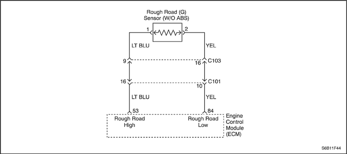
The VR sensor is used to detecting the road situation.
By sensing difference of wheel rotation duration caused by bumps or potholes in the road, the Engine Control Module (ECM) can determine if the changes in crankshaft speed are due to engine misfire or are driveline induced. If the VR sensor detects a rough road condition, the ECM misfire detection diagnostic will be de-activated.
Conditions for Running the DTC
Conditions for Setting the DTC
- Minimum sensor voltage is lower than 1.3103 V.
Or
- Maximum sensor voltage is higher than 2.2141 V.
Or
- Difference between Min. and Max. sensor voltage is greater than 0.0587 V.
Action Taken When the DTC Sets
- The Malfunction Indicator Lamp (MIL) will not illuminate.
- The ECM will record operating conditions at the time the diagnostic fails. This information will be stored in the Freeze Frame and Records buffers.
Conditions for Clearing the MIL/DTC
- A history DTC will clear after 40 warm up cycles without a fault.
- DTC(s) can be cleared by using the scan tool.
DTC P1390 - Rough Road Sensor Circuit Fault (NON ABS)
| Step | Action | Value(s) | Yes | No |
| 1 | Perform the Diagnostic System Check. Is the system check complete? | - | Go to Step 2 | |
| 2 | - Turn the ignition switch to LOCK.
- Install a scan tool to the Data Link Connector (DLC).
- Turn the ignition switch to ON.
Does the scan tool indicate that this DTC failed? | - | Go to Step 5 | Go to Step 3 |
| 3 | Check for poor or fault connection between the Engine Control Module (ECM) and the Rough Road sensor. Is the problem found? | - | Go to Step 4 | |
| 4 | Repair the connection as needed. Is the repair complete? | - | Go to Step 8 | - |
| 5 | - Turn the ignition switch to LOCK.
- Disconnect the rough road sensor connector.
- Turn the ignition switch to ON.
- Observe the rough road sensor value displayed on the scan tool.
Is the VR sensor value near the specified value? | 0 V | Go to Step 6 | Go to Step 9 |
| 6 | - Turn the ignition switch to LOCK.
- Disconnect the ECM connector and rough road sensor connector.
- Check for an open, a short to ground, or a short to battery in the wire between the ECM connector and the rough road sensor connector.
Is the problem found? | - | Go to Step 6 | Go to Step 8 |
| 7 | Repair the wire as needed. Is the repair complete? | - | Go to Step 10 | - |
| 8 | Replace the ECM. Is the replacement complete? | - | Go to Step 11 | - |
| 9 | Replace the rough road sensor. Is the replacement complete | - | Go to Step 10 | - |
| 10 | - Using the scan tool, clear the DTCs.
- Start the engine and idle at normal operating temperature.
- Operate the vehicle within the conditions for setting this DTC as specified in the supporting text.
Does the scan tool indicate that this diagnostic ran and passed? | - | Go to Step 11 | Go to Step 2 |
| 12 | Check if any additional DTCs are set. Are any DTCs displayed that have not been diagnosed? | - | Go to applicable DTC table | System OK |
Diagnostic Trouble Code (DTC) P1396
Rough Road Data Invalid (ABS)
Circuit Description
The wheel speed sensor is used to detecting the road situation.
As the wheel is rotated, the wheel speed sensor produces an AC voltage that increase with wheel speed. The EBCM uses the frequency of the AC signal to calculate wheel speed. The wheel speed sensor is connected to EBCM by a "twisted pair" of wires. Twisting reduces noise susceptibility that may cause a DTC to set. If the wheel speed sensor detects a rough road condition, the ECM misfire detection diagnostic will be de-activated.
Conditions for Running the DTC
Conditions for Setting the DTC
- ECM detects wheel speed acquisition from EBCM is invalid.
Action Taken When the DTC Sets
- The Malfunction Indicator Lamp (MIL) will not illuminate.
- The ECM will record operating conditions at the time the diagnostic fails. This information will be stored in the Freeze Frame and Records buffers.
Conditions for Clearing the MIL/DTC
- A history DTC will clear after 40 warm up cycles without a fault.
- DTC(s) can be cleared by using the scan tool.
DTC P1396 - Rough Road Data Invalid (ABS)
| Step | Action | Value(s) | Yes | No |
| 1 | Perform the Diagnostic System Check. Was the check performed? | - | Go to Step 2 | |
| 2 | Was the check performed? | - | System OK | |
| © Copyright Chevrolet Europe. All rights reserved |