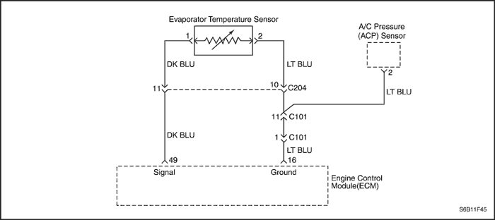
Diagnostic Trouble Code (DTC)
P1535 - Evaporator Temperature Sensor High Voltage
P1536 - Evaporator Temperature Sensor Low Voltage
Circuit Description
A semiconductor which resistance is noticeably changed as the change of temperature. When the refrigerant temperature of the evaporator drops to 05C (05F) and below, the evaporator cores get stuck with frost or ice, reducing the airflow, lowering the cooling capacity. The thermistor is a sensor which is used to prevent from frosting or icing. The thermistor is installed on the evaporator.
Conditions for Running the DTC
- Engine is running.
- A/C switch is ON.
- Engine coolant temperature (ECT) is higher than 39.75°C (103.55°F).
- A/C relay is ON for more than 131 seconds.
Conditions for Setting the DTC
(P1535)
- Evaporator temperature sensor signal is higher than 4.98 V.
(P1536)
- Evaporator temperature sensor signal is lower than 0.0293 V.
Action Taken When the DTC Sets
- The Malfunction Indicator Lamp (MIL) will not illuminate.
- The ECM will record operating conditions at the time the diagnostic fails. This information will be stored Failure Records buffers.
Conditions for Clearing the MIL/DTC
- A history DTC will clear after 40 warm-up cycles without a fault.
- DTC(s) can be cleared by using the scan tool.
DTC P1535 - Evaporator Temperature Sensor High Voltage
DTC P1536 - Evaporator Temperature Sensor Low Voltage
| Step | Action | Value(s) | Yes | No |
| 1 | Perform the Diagnostic System Check. Is the system check complete? | - | Go to Step 2 | |
| 2 | - Turn the ignition switch to LOCK.
- Disconnect the evaporator temperature sensor.
- Measure the resistance between evaporator temperature sensor terminals 1 and 2.
Does the resistance within the specified value? | 0 Ω | Go to Step 7 | Go to Step 3 |
| 3 | - Turn the ignition switch to LOCK.
- Check for an open, a short to ground, or a short to battery in the signal circuit, at terminal 1 in the sensor harness connector.
Did you find the problem? | - | Go to Step 4 | Go to Step 5 |
| 4 | Repair the wire or the connector between the terminal 49 of ECM and evaporator temperature sensor terminal 2. Is the repair complete? | - | Go to Step 9 | - |
| 5 | - Turn the ignition switch to LOCK.
- Disconnect the ECM.
- Check for an open, a short to ground, or a short to battery in the low reference circuit, at terminal 2 in the sensor harness connector.
Did you find the problem? | - | Go to Step 6 | Go to Step 8 |
| 6 | Repair the wire or the connector between the ECM wiring connector terminal 16 and evaporator temperature sensor terminal 2. Is the repair complete? | - | Go to Step 9 | - |
| 7 | Replace the evaporator temperature sensor. Is the replacement complete? | - | Go to Step 9 | - |
| 8 | - Turn the ignition switch to LOCK.
- Replace the ECM.
Is the repair complete? | - | Go to Step 9 | - |
| 9 | - Using the scan tool, clear the Diagnostic Trouble Codes (DTCs).
- Start the engine and idle at normal operating temperature.
- Operate the vehicle within the conditions for setting this DTC as specified in the supporting text.
Does the scan tool indicate that this diagnostic has run and passed? | - | Go to Step 10 | Go to Step 2 |
| 10 | Check if any additional DTCs are set. Are any DTCs displayed that have not been diagnosed? | - | Go to applicable DTC table | System OK |
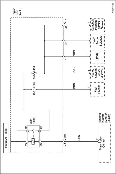


Diagnostic Trouble Code (DTC) P1610
Main Relay High Voltage
Circuit Description
When the ignition switch to ON, main relay will be grounded to ECM internal ground by ECM controlling.
A system voltage Diagnostic Trouble Code (DTC) will set whenever the voltage is above a calibrated value.
Conditions for Running the DTC
Conditions for Setting the DTC
- A short to battery condition in the main relay circuit exists.
Action Taken When the DTC Sets
- The Malfunction Indicator Lamp (MIL) will not illuminate.
- The ECM will record operating conditions at the time the diagnostic fails. This information will be stored in the Freeze Frame and Records buffers.
Conditions for Clearing the MIL/DTC
- A history DTC will clear after 40 warm up cycles without a fault.
- DTC(s) can be cleared by using the scan tool.
Diagnostic Aids
Inspect harness connectors for backed-out terminals, improper mating, broken locks, improperly formed or damaged terminals, and poor terminal-to-wire connection at the ECM.
Inspect the wiring harness for damage. If the harness appears to be OK, observe the A/C pressure display on the scan tool while moving the connectors and wiring harnesses related to the ACP sensor. A change in the A/C pressure display will indicate the location of the fault.
If DTC P1610 cannot be duplicated, reviewing the Fail Records vehicle mileage since the diagnostic test last failed may help determine how often the condition that caused the DTC to set occurs. This may assist in diagnosing the condition.
DTC P1610 - Main Relay High Voltage
| Step | Action | Value(s) | Yes | No |
| 1 | Perform the Diagnostic System Check. Is the system check complete? | - | Go to Step 2 | |
| 2 | - Turn the ignition switch to LOCK.
- Disconnect the main relay.
- Measure the resistance between main relay terminals 85 and 86.
Does the resistance between the specified value? | 75~85Ω | Go to Step 3 | Go to Step 8 |
| 3 | Check for a poor or fault connection between the main relay connector terminal 85, 30 and the battery positive terminal. Is the problem found? | - | Go to Step 4 | Go to Step 5 |
| 4 | Repair the connection as needed. Is the repair complete? | - | Go to Step 10 | - |
| 5 | - Disconnect the Engine Control Module(ECM) connector.
- Check for a short to battery in the wire between the main relay connector terminal 86 and the ECM connector terminal 7.
Is the problem found? | - | Go to Step 7 | Go to Step 6 |
| 6 | Check for a short to battery in the wire between the main relay connector terminal 87 and the ECM connector terminal 66 Is the problem found? | - | Go to Step 7 | Go to Step 9 |
| 7 | Repair the wire as needed. Is the repair complete? | - | Go to Step 10 | - |
| 8 | Replace the main relay. Is the replacement complete? | - | Go to Step 10 | - |
| 9 | Replace the ECM. Is the replacement complete? | - | Go to Step 11 | - |
| 10 | - Using the scan tool, clear the Diagnostic Trouble Codes (DTCs).
- Start the engine and idle at normal operating temperature.
- Operate the vehicle within the conditions for setting this DTC as specified in the supporting text.
Does the scan tool indicate that this diagnostic has run and passed? | - | Go to Step 11 | Go to Step 2 |
| 11 | Check if any additional DTCs are set. Are any DTCs displayed that that have not been diagnosed? | - | Go to applicable DTC table | System OK |
Diagnostic Trouble Code (DTC) P1611
Main Relay Low Voltage
Circuit Description
When the ignition switch to ON, main relay will be grounded to ECM internal ground by ECM controlling.
A system voltage Diagnostic Trouble Code (DTC) will set whenever the voltage is below a calibrated value.
Conditions for Running the DTC
Conditions for Setting the DTC
- A short to ground or an open in the main relay circuit exists.
Action Taken When the DTC Sets
- The Malfunction Indicator Lamp (MIL) will not illuminate.
- The ECM will record operating conditions at the time the diagnostic fails. This information will be stored in the Freeze Frame and Records buffers.
Conditions for Clearing the MIL/DTC
- A history DTC will clear after 40 warm up cycles without a fault.
- DTC(s) can be cleared by using the scan tool.
Diagnostic Aids
Inspect harness connectors for backed-out terminals, improper mating, broken locks, improperly formed or damaged terminals, and poor terminal-to-wire connection at the ECM.
Inspect the wiring harness for damage. If the harness appears to be OK, observe the A/C pressure display on the scan tool while moving the connectors and wiring harnesses related to the ACP sensor. A change in the A/C pressure display will indicate the location of the fault.
If DTC P1611 cannot be duplicated, reviewing the Fail Records vehicle mileage since the diagnostic test last failed may help determine how often the condition that caused the DTC to set occurs. This may assist in diagnosing the condition.
DTC P1611 - Main Relay Low Voltage
| Step | Action | Value(s) | Yes | No |
| 1 | Perform the Diagnostic System Check. Is the system check complete? | - | Go to Step 2 | |
| 2 | - Turn the ignition switch to LOCK.
- Disconnect the main relay.
- Measure the resistance between main relay terminals 85 and 86.
Does the resistance between the specified value? | 75~85Ω | Go to Step 3 | Go to Step 8 |
| 3 | Check for a poor or fault connection between the main relay connector terminal 85, 30 and the battery positive terminal. Is the problem found? | - | Go to Step 4 | Go to Step 5 |
| 4 | Repair the connection as needed. Is the repair complete? | - | Go to Step 10 | - |
| 5 | - Disconnect the Engine Control Module(ECM) connector.
- Check for a short to ground or an open in the wire between the main relay connector terminal 86 and the ECM connector terminal 7.
Is the problem found? | - | Go to Step 7 | Go to Step 6 |
| 6 | Check for a short to ground or an open in the wire between the main relay connector terminal 87 and the ECM connector terminal 66. Is the problem found? | - | Go to Step 7 | Go to Step 9 |
| 7 | Repair the wire as needed. Is the repair complete? | - | Go to Step 10 | - |
| 8 | Replace the main relay. Is the replacement complete? | - | Go to Step 10 | - |
| 9 | Replace the ECM. Is the replacement complete? | - | Go to Step 11 | - |
| 10 | - Using the scan tool, clear the Diagnostic Trouble Codes (DTCs).
- Start the engine and idle at normal operating temperature.
- Operate the vehicle within the conditions for setting this DTC as specified in the supporting text.
Does the scan tool indicate that this diagnostic has run and passed? | - | Go to Step 11 | Go to Step 2 |
| 11 | Check if any additional DTCs are set. Are any DTCs displayed that that have not been diagnosed? | - | Go to applicable DTC table | System OK |
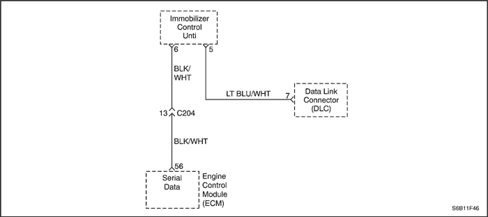
Diagnostic Trouble Code (DTC) P1628
Immobilizer No Successful Communication
Circuit Description
When the ignition switch is turned to ON, the key tested by immobilizer anti-theft system. While the key code is being read by immobilizer control unit or integrated anti-theft control unit, the engine can start run with any key that will turn the lock cylinder. the key code is read and compared with key codes that have been stored in the memory of the immobilizer control unit. If a valid key is detected, the immobilizer control unit sends a serial data release message to the Engine Control Module (ECM). Included in the release message is an identification (ID) code which assures that neither the immobilizer control unit nor the ECM have been substituted to defeat the system. If the ECM receives an invalid release message, the ECM performs the following action:
- Disable the fuel injector circuit.
- Disable the fuel pump circuit.
- Disable the ignition coil.
- A Diagnostic Trouble Code (DTC) will stored if detect communication link failure between the ECM and immobilizer control unit.
Conditions for Running the DTC
Conditions for Setting the DTC
- No immobilizer message ID for ECM.
Action Taken When the DTC Sets
- The Malfunction Indicator Lamp (MIL) will not illuminate.
- The ECM will record operating conditions at the time the diagnostic fails. This information will be stored in the Freeze Frame and Records buffers.
Conditions for Clearing the MIL/DTC
- A history DTC will clear after 40 warm up cycles without a fault.
- DTC(s) can be cleared by using the scan tool.
DTC P1628 - Immobilizer No Successful Communication
| Step | Action | Value(s) | Yes | No |
| 1 | Perform the Diagnostic System Check. Is the system check complete? | - | Go to Step 2 | |
| 2 | - Turn the ignition OFF.
- Install a scan too to the Data Link Connector (DLC).
- Turn the ignition ON.
- Select IMMOBILIZER DIAGNOSIS STATUS from the scan tool menu.
Is the communication established between the scan tool and the immobilizer control unit? | - | Go to Step 3 | |
| 3 | - Turn the ignition OFF.
- Disconnect the Immobilizer Control Unit and Engine Control Module (ECM) connectors.
- Measure the resistance between terminal 6 of immoblizer control unit and terminal 56 of the ECM.
Is the resistance within the specified value? | 0Ω | Go to Step 5 | Go to Step 4 |
| 4 | Repair an open circuit between terminal 6 of immobilizer control unit and terminal 56 of the ECM. Is the repair complete? | - | Go to Step 8 | - |
| 5 | Check the terminals in immobilizer control unit and the ECM for damages and repair as needed. Is the repair complete? | - | Go to Step 8 | Go to Step 6 |
| 6 | Replace the immobilizer control unit. Is the repair complete? | - | Go to Step 8 | Go to Step 7 |
| 7 | - Turn the ignition OFF.
- Replace the ECM.
Is the repair complete? | - | Go to Step 8 | - |
| 8 | - Using the scan tool, clear the Diagnostic Trouble Codes (DTCs).
- Start the engine and idle at normal operating temperature.
- Operate the vehicle within the Conditions for setting this DTC as specified in the supporting text.
Does the scan tool indicate that this diagnostic has run and passed? | - | Go to Step 9 | Go to Step 2 |
| 9 | Check if any additional DTCs are set. Are any DTCs displayed that have not been diagnosed? | - | Go to applicable DTC table | System OK |
Diagnostic Trouble Code (DTC) P1629
Immobilizer Wrong Computation
Circuit Description
When the ignition switch is turned to ON, the key tested by immobilizer anti-theft system. While the key code is being read by immobilizer control unit or integrated anti-theft control unit, the engine can start run with any key that will turn the lock cylinder. the key code is read and compared with key codes that have been stored in the memory of the immobilizer control unit. If a valid key is detected, the immobilizer control unit sends a serial data release message to the Engine Control Module (ECM). Included in the release message is an identification (ID) code which assures that neither the immobilizer control unit nor the ECM have been substituted to defeat the system. If the ECM receives an invalid release message, the ECM performs the following action:
- Disable the fuel injector circuit.
- Disable the fuel pump circuit.
- Disable the ignition coil.
A Diagnostic Trouble Code (DTC) will stored if detect communication link failure between the ECM and immobilizer control unit.
Conditions for Running the DTC
Conditions for Setting the DTC
- No immobilizer messafe ID for ECM.
Action Taken When the DTC Sets
- The Malfunction Indicator Lamp (MIL) will not illuminate.
- The ECM will record operating conditions at the time the diagnostic fails. This information will be stored in the Freeze Frame and Records buffers.
Conditions for Clearing the MIL/DTC
- A history DTC will clear after 40 warm up cycles without a fault.
- DTC(s) can be cleared by using the scan tool.
DTC P1629 - Immobilizer Wrong Computation
| Step | Action | Value(s) | Yes | No |
| 1 | Perform the Diagnostic System Check. Is the system check complete? | - | Go to Step 2 | |
| 2 | - Turn the ignition OFF.
- Install a scan too to the Data Link Connector (DLC).
- Turn the ignition ON.
- Select IMMOBILIZER DIAGNOSIS STATUS from the scan tool menu.
Is the communication established between the scan tool and the immobilizer control unit? | - | Go to Step 3 | |
| 3 | - Turn the ignition OFF.
- Disconnect the Immobilizer Control Unit and Engine Control Module (ECM) connectors.
- Measure the resistance between terminal 6 of immoblizer control unit and terminal 56 of the ECM.
Is the resistance within the specified value? | 0Ω | Go to Step 5 | Go to Step 4 |
| 4 | Repair an open circuit between terminal 6 of immobilizer control unit and terminal 56 of the ECM. Is the repair complete? | - | Go to Step 8 | - |
| 5 | Check the terminals in immobilizer control unit and the ECM for damages and repair as needed. Is the repair complete? | - | Go to Step 8 | Go to Step 6 |
| 6 | Replace the immobilizer control unit. Is the repair complete? | - | Go to Step 8 | Go to Step 7 |
| 7 | - Turn the ignition OFF.
- Replace the ECM.
Is the repair complete? | - | Go to Step 8 | - |
| 8 | - Using the scan tool, clear the Diagnostic Trouble Codes (DTCs).
- Start the engine and idle at normal operating temperature.
- Operate the vehicle within the Conditions for setting this DTC as specified in the supporting text.
Does the scan tool indicate that this diagnostic has run and passed? | - | Go to Step 9 | Go to Step 2 |
| 9 | Check if any additional DTCs are set. Are any DTCs displayed that have not been diagnosed? | - | Go to applicable DTC table | System OK |
Diagnostic Trouble Code (DTC) P1650
Malfunction Indicator Lamp (MIL) High Voltage
Circuit Description
When the ignition switch to ON, the Malfunction Indicator Lamp (MIL) is ON steady.
When the engine cranking, the Malfunction Indicator Lamp (MIL) is OFF after one flashing time.
If a system have some difficulties, the Malfunction Indicator Lamp (MIL) is ON.
Conditions for Running the DTC
Conditions for Setting the DTC
- The ECM detects a continuous short to voltage in the signal circuit.
Action Taken When the DTCs Sets
- The Malfunction Indicator Lamp (MIL) will illuminate.
- The ECM will record operating conditions at the time the diagnostic fails. The information will be stored in the Freeze Frame and Failure Records buffers.
- A history DTC is stored.
Conditions for Clearing the MIL/DTC
- The MIL will turn off at the end of three consecutive validation cycles in which the diagnostic runs without a fault.
- A history DTC will clear after 40 warm-up cycles without a fault.
- DTC(s) can be cleared by using the scan tool.
Diagnostic Aids
An Intermittent problem may be caused by a poor connection, rubbed through wire insulation, or wire that is broken inside the insulation.
Any circuitry, that is suspected as causing the complaint, should be thoroughly checked for the following conditions.
- Backed-out terminals
- Improper mating
- Broken locks
- Improperly formed
- Damaged terminals
- Poor terminals to wire connection
- Physical damage to the wiring harness
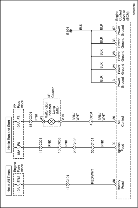
DTC P1650 - Malfunction Indicator Lamp (MIL) High Voltage
| Step | Action | Value(s) | Yes | No |
| 1 | Perform the Diagnostic System Check. Is the system check complete? | - | Go to Step 2 | |
| 2 | - Turn the ignition switch to LOCK.
- Disconnect the cluster wiring connector.
- With the test light, connected to ground, probe the ignition feed circuit, at terminal A5 in the cluster harness connector.
Does the resistance within the specified value? | 0Ω | Go to Step 3 | Go to Step 6 |
| 3 | - Turn the ignition switch to LOCK.
- With the test light, connected to ground, probe the MIL control circuit, at ECM wiring connector terminal 39.
Does the test light illuminate? | - | Go to Step 4 | - |
| 4 | - Turn the ignition switch to LOCK.
- Replace the cluster.
Is the replacement complete? | - | Go to Step 6 | - |
| 5 | Repair a short to battery between the ECM wiring connector terminal 39 and cluster wiring connector terminal A14. Is the repair complete? | - | Go to Step 6 | - |
| 6 | - Using the scan tool, clear the Diagnostic Trouble Codes(DTCs).
- Start the engine and idle at normal operating temperature.
- Operate the vehicle within the conditions for setting this DTC as specified in the supporting text.
Does the scan tool indicate that this diagnostic has run and passed? | - | Go to Step 7 | Go to Step 2 |
| 7 | Check if any additional DTCs are set. Are any DTCs displayed that have not been diagnosed? | - | Go to applicable DTC table | System OK |
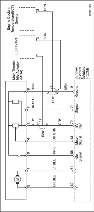
Diagnostic Trouble Code (DTC) P2101
Idle Charge Actuator Circuit Fault
Circuit Description
The main throttle idle actuator (MTIA) assembly is a throttle body with an integrated motor that is used to control the engine speed at idle. The engine control module (ECM) commands the integrated idle speed control (ISC) motor to adjust the throttle angle for idle speed control. The ECM uses a high control circuit and a low control circuit to command the ISC motor. If the ECM detects a fault with the ISC motor control circuits or motor, this DTC sets.
Conditions for Running the DTC
- The engine is running.
- The ISC motor angle is between 0.235° and 5.628°.
- No failure on MTIA.
Conditions for Setting the DTC
- The ECM detects that the commanded duty cycle is more than 59.5% for 5 seconds.
Or,
- The ECM detects that the commanded duty cycle is less than -70% for 5 seconds.
Action Taken When the DTC Sets
- The Malfunction Indicator Lamp (MIL) will illuminate.
- The ECM will record operating conditions at the time the diagnostic fails. The information will be stored in the freeze frame and failure records buffers.
- A history DTC is stored.
Conditions for Clearing the MIL/DTC
- The MIL will turn off at the end of 3 consecutive validation cycles in which the diagnostic runs without a fault.
- A history DTC will clear after 40 warm up cycles without a fault.
- DTC(s) can be cleared by using the scan tool.
DTC P2101 – Idle Charge Actuator Circuit Fault
| Step | Action | Value(s) | Yes | No |
| 1 | Did you perform the Diagnostic System Check? | - | Go to Step 2 | |
| 2 | - Turn ON the ignition, with the engine OFF.
- Observe the DTC information with a scan tool.
Is DTC P0122, P0123, P0222 or P0223 also set? | - | Go to applicable DTC table | Go to Step 3 |
| 3 | - Start the engine.
- Observe the ISC motor position sensor parameter with a scan tool while depressing the accelerator pedal.
Does the ISC motor position sensor parameter change when the throttle is open? | - | Go to Step 4 | Go to Step 5 |
| 4 | - Observe the Freeze Frame/Failure Records for this DTC.
- Turn OFF the ignition for 30 seconds.
- Start the engine.
- Operate the vehicle within the Conditions for Running the DTC. You may also operate the vehicle within the conditions that you observed from the Freeze Frame/Failure Records.
Did the DTC fail this ignition? | - | Go to Step 5 | |
| 5 | - Turn ON the ignition, with the engine OFF.
- Measure the high control circuit of the ISC motor to a good ground with a DMM.
Is the voltage more than the specified value? | 11 V | Go to Step 6 | Go to Step 9 |
| 6 | Measure the low control circuit of the ISC motor to a good ground with a DMM. Is the voltage more than the specified value? | 11 V | Go to Step 7 | Go to Step 10 |
| 7 | While Measuring the voltage at the high control circuit of the ISC motor, toggle the idle switch circuit to a good ground with a 3-amp fused jumper wire. Does the voltage value change when the jumper is installed? | - | Go to Step 8 | Go to Step 11 |
| 8 | While Measuring the voltage at the low control circuit of the ISC motor, toggle the idle switch circuit to a good ground with a 3-amp fused jumper wire. Does the voltage value change when the jumper is installed? | - | Go to Step 13 | Go to Step 12 |
| 9 | Test the high control circuit of the ISC motor for the following: - An open
- A short to ground
- A high resistance
Did you find and correct the condition? | - | Go to Step 19 | Go to Step 16 |
| 10 | Test the low control circuit of the ISC motor for the following: - An open
- A short to ground
- A high resistance
Did you find and correct the condition? | - | Go to Step 19 | Go to Step 16 |
| 11 | Test the high control circuit of the ISC motor for a short to voltage. Did you find and correct the condition? | - | Go to Step 19 | Go to Step 16 |
| 12 | Important : The engine control module (ECM) may be damaged if the circuit is shorted to battery positive voltage. Test the low control circuit of the ISC motor for a short to voltage. Did you find and correct the condition? | - | Go to Step 19 | Go to Step 16 |
| 13 | Test the high control circuit of the ISC motor for a high resistance or a short to the low control circuit of the ISC motor. Did you find and correct the condition? | - | Go to Step 19 | Go to Step 14 |
| 14 | Test the low control circuit of the ISC motor for a high resistance. Did you find and correct the condition? | - | Go to Step 19 | Go to Step 15 |
| 15 | Test for shorted terminals and for poor connections at the throttle body assembly. Did you find and correct the condition? | - | Go to Step 19 | Go to Step 17 |
| 16 | Test for shorted terminals and for poor connections at the engine control module (ECM). Did you find and correct the condition? | - | Go to Step 19 | Go to Step 18 |
| 17 | Replace the throttle body assembly. Did you complete the replacement? | - | Go to Step 19 | - |
| 18 | Replace the ECM. Did you complete the replacement? | - | Go to Step 19 | - |
| 19 | - Clear the DTCs with a scan tool.
- Turn OFF the ignition for 30 seconds.
- Start the engine.
- Operate the vehicle within the Conditions for Running the DTC. You may also operate the vehicle within the conditions that you observed from the Freeze Frame/Failure Records.
Did the DTC fail this ignition? | - | Go to Step 2 | Go to Step 20 |
| 20 | Check if any additional DTCs are set. Are there any DTCs that have not been diagnosed? | - | Go to applicable DTC table | System OK |
Diagnostic Trouble Code (DTC) P2118
Idle Charge Actuator Mechanical Error
Circuit Description
The main throttle idle actuator (MTIA) assembly is a throttle body with an integrated motor that is used to control the engine speed at idle. The engine control module (ECM) commands the integrated idle speed control (ISC) motor to adjust the throttle angle for idle speed control. The ECM uses a high control circuit and a low control circuit to command the ISC motor. If the ECM detects that the actual ISC motor position can not be commanded to the desired position, this DTC sets.
Conditions for Running the DTC
- The engine is running.
- The ISC motor angle is between 0.235° and 5.628°.
- No failure on MTIA.
Conditions for Setting the DTC
- The ECM detects that the commanded duty cycle is more than 59.5% for 10 seconds.
Or,
- The ECM detects that the commanded duty cycle is less than -70% for 10 seconds.
Action Taken When the DTC Sets
- The Malfunction Indicator Lamp (MIL) will illuminate.
- The ECM will record operating conditions at the time the diagnostic fails. The information will be stored in the freeze frame and failure records buffers.
- A history DTC is stored.
Conditions for Clearing the MIL/DTC
- The MIL will turn off at the end of 3 consecutive validation cycles in which the diagnostic runs without a fault.
- A history DTC will clear after 40 warm up cycles without a fault.
- DTC(s) can be cleared by using the scan tool.
Test Description
The numbers below refer to the step numbers on the diagnostic table.
- This step tests for a high resistance on the ISC motor position sensor 5-volt reference circuit.
- This step tests for a high resistance on the ISC motor high control circuit.
- This step tests for a high resistance on the ISC motor low control circuit.
DTC P2118 – Idle Charge Actuator Mechanical Error
| Step | Action | Value(s) | Yes | No |
| 1 | Did you perform the Diagnostic System Check? | - | Go to Step 2 | |
| 2 | - Turn ON the ignition, with the engine OFF.
- Observe the DTC information with a scan tool.
Is DTC P0122, P0123, P0222, P0223, or P2101 also set? | - | Go to applicable DTC table | Go to Step 3 |
| 3 | - Start the engine.
- Observe the ISC motor position sensor parameter with a scan tool while depressing the accelerator pedal.
Does the ISC motor position sensor parameter change when the throttle is open? | - | Go to Step 4 | Go to Step 5 |
| 4 | - Observe the Freeze Frame and the Failure records data for this DTC.
- Turn OFF the ignition for 30 seconds.
- Start the engine.
- Operate the vehicle within the Conditions for running the DTC. You may also operate the vehicle within the conditions that you observed from the Freeze Frame/Failure Records data.
Does the DTC fail this ignition cycle? | - | Go to Step 5 | |
| 5 | - Turn OFF the ignition.
- Inspect for the following conditions:
- The throttle body for damage and/or tampering
- For vacuum leaks
- For a restricted air intake system
- For excessive deposits on the throttle plate
- For excessive deposits in the throttle bore
- The throttle shaft for binding
- The throttle linkage or the throttle cable for binding
- For an incorrectly installed PCV valve and hose
- For a malfunctioning PCV valve
Did you find and correct the condition? | - | Go to Step 17 | Go to Step 6 |
| 6 | - Turn OFF the ignition.
- Disconnect the throttle body harness connector.
- Turn ON the ignition, with the engine OFF.
Notice : Do NOT use the low reference circuit in the component harness connector for this test. Damage to the control module may occur due to excessive current draw. - Connect a test lamp between the 5-volt reference circuit of the ISC motor position sensor and a good ground.
- Connect a DMM to the probe of the test lamp and a good ground.
Is the voltage more than the specified value? | 4.8 V | Go to Step 7 | Go to Step 9 |
| 7 | - Connect a test lamp between the ISC motor high control circuit and a good ground.
- Connect a DMM to the probe of the test lamp and a good ground.
Is the voltage more than the specified value? | 11.5 V | Go to Step 8 | Go to Step 10 |
| 8 | - Connect a test lamp between the ISC motor low control circuit and a good ground.
- Connect a DMM to the probe of the test lamp and a good ground.
Is the voltage more than the specified value? | 10.5 V | Go to Step 12 | Go to Step 11 |
| 9 | Test the 5-volt reference circuit of the ISC motor position sensor for a high resistance. Did you find and correct the condition? | - | Go to Step 17 | Go to Step 14 |
| 10 | Test the high control circuit of the ISC motor for a high resistance. Did you find and correct the condition? | - | Go to Step 17 | Go to Step 14 |
| 11 | Test the low control circuit of the ISC motor for a high resistance. Did you find and correct the condition? | - | Go to Step 17 | Go to Step 14 |
| 12 | Test the signal circuit of the ISC motor position sensor for a high resistance. Did you find and correct the condition? | - | Go to Step 17 | Go to Step 13 |
| 13 | Test for an intermittent and for a poor connection at the throttle body assembly. Did you find and correct the condition? | - | Go to Step 17 | Go to Step 15 |
| 14 | Test for an intermittent and for a poor connection at the engine control module (ECM). Did you find and correct the condition? | - | Go to Step 17 | Go to Step 16 |
| 15 | Replace the throttle body assembly. Did you complete the replacement? | - | Go to Step 17 | - |
| 16 | Replace the ECM. Did you complete the replacement? | - | Go to Step 17 | - |
| 17 | - Clear the DTCs with a scan tool.
- Turn the ignition OFF for 30 seconds.
- Start the engine.
- Operate the vehicle within the Conditions for Running the DTC. You may also operate the vehicle within the conditions that you observed from the Freeze Frame/Failure Records.
Does the DTC fail this ignition? | - | Go to Step 2 | Go to Step 18 |
| 18 | Check if any additional DTCs are set. Are there any DTCs that have not been diagnosed? | - | Go to applicable DTC table | System OK |
Diagnostic Trouble Code (DTC) P2119
Idle Charge Actuator Functional Error
Circuit Description
The main throttle idle actuator (MTIA) assembly is a throttle body with an integrated motor that is used to control the engine speed at idle. The engine control module (ECM) commands the integrated idle speed control (ISC) motor to adjust the throttle angle for idle speed control. The ECM uses a high control circuit and a low control circuit to command the ISC motor. If the ECM detects the adaptation value exceeds the throttle position (TP) sensor or the idle speed control (ISC) position sensor values, this DTC sets.
Conditions for Running the DTC
Conditions for Setting the DTC
- The ECM detects the adaptation value exceeds the throttle position (TP) sensor or the idle speed control (ISC) position sensor values.
Action Taken When the DTC Sets
- The Malfunction Indicator Lamp (MIL) will illuminate.
- The ECM will record operating conditions at the time the diagnostic fails. The information will be stored in the freeze frame and failure records buffers.
- A history DTC is stored.
Conditions for Clearing the MIL/DTC
- The MIL will turn off at the end of 3 consecutive validation cycles in which the diagnostic runs without a fault.
- A history DTC will clear after 40 warm up cycles without a fault.
- DTC(s) can be cleared by using the scan tool.
Test Description
The numbers below refer to the step numbers on the diagnostic table.
- This step tests for a high resistance on the ISC motor position sensor 5-volt reference circuit.
DTC P2119 – Idle Charge Actuator Functional Error
| Step | Action | Value(s) | Yes | No |
| 1 | Did you perform the Diagnostic System Check? | - | Go to Step 2 | |
| 2 | - Turn ON the ignition, with the engine OFF.
- Observe the DTC information with a scan tool.
Is DTC P0122, P0123, P0222, P0223, P0462, P0463, P0510, P2101, or P2118 also set? | - | Go to applicable DTC table | Go to Step 3 |
| 3 | - Start the engine.
- Observe the ISC motor position sensor parameter with a scan tool while depressing the accelerator pedal.
Does the ISC motor position sensor parameter change when the throttle is open? | - | Go to Step 4 | Go to Step 5 |
| 4 | - Observe the Freeze Frame and the Failure records data for this DTC.
- Turn OFF the ignition for 30 seconds.
- Start the engine.
- Operate the vehicle within the Conditions for running the DTC. You may also operate the vehicle within the conditions that you observed from the Freeze Frame/Failure Records data.
Does the DTC fail this ignition cycle? | - | Go to Step 5 | |
| 5 | - Turn OFF the ignition.
- Disconnect the throttle body harness connector.
- Turn ON the ignition, with the engine OFF.
Notice : Do NOT use the low reference circuit in the component harness connector for this test. Damage to the control module may occur due to excessive current draw. - Connect a test lamp between the 5-volt reference circuit of the ISC motor position sensor and a good ground.
- Connect a DMM to the probe of the test lamp and a good ground.
Is the voltage more than the specified value? | 4.8 V | Go to Step 7 | Go to Step 6 |
| 6 | Test the 5-volt reference circuit of the ISC motor position sensor for a high resistance. Did you find and correct the condition? | - | Go to Step 11 | Go to Step 8 |
| 7 | Test for an intermittent and for a poor connection at the throttle body assembly. Did you find and correct the condition? | - | Go to Step 11 | Go to Step 9 |
| 8 | Test for an intermittent and for a poor connection at the engine control module (ECM). Did you find and correct the condition? | - | Go to Step 11 | Go to Step 10 |
| 9 | Replace the throttle body assembly. Did you complete the replacement? | - | Go to Step 11 | - |
| 10 | Replace the ECM. Did you complete the replacement? | - | Go to Step 11 | - |
| 11 | - Clear the DTCs with a scan tool.
- Turn the ignition OFF for 30 seconds.
- Start the engine.
- Operate the vehicle within the Conditions for Running the DTC. You may also operate the vehicle within the conditions that you observed from the Freeze Frame/Failure Records.
Does the DTC fail this ignition? | - | Go to Step 2 | Go to Step 12 |
| 12 | Check if any additional DTCs are set. Are there any DTCs that have not been diagnosed? | - | Go to applicable DTC table | System OK |
 | |  | |
| © Copyright Chevrolet Europe. All rights reserved |