SECTION 4F
ANTILOCK BRAKE SYSTEM
Caution : Disconnect the negative battery cable before removing or installing any electrical unit or when atool or equipment could easily come in contact with exposed electrical terminals. Disconnecting this cablewill help prevent personal injury and damage to the vehicle. The ignition must also be in LOCK unlessotherwise noted.
SPECIFICATIONS
General Specifications
Application | Unit | Description |
Antilock Brake System (ABS) Mode | - | 4 Channel 4 Sensor |
ABS Main Relay Operation Voltage | V | 10~16 |
Front Wheel Speed Sensor: | - | - |
Resistance | Ω | 988~1,208 |
Air Gap | mm (inch) | 0.5~1.2 (0.0197~0.0472) |
Rear Wheel Speed Sensor: | - | - |
Resistance | Ω | 2,295~2,500 |
Air Gap | mm (inch) | 0.6~1.2 (0.0236~0.0472) |
Speed Ring | - | - |
Outside Diameter (Front) | mm (inch) | 83.72 (3.2961) |
Outside Diameter (Rear) | mm (inch) | 77 (3.0315) |
Inside Diameter (Front) | mm (inch) | 73.75 (2.9035) |
Inside Diameter (Rear) | mm (inch) | 67 (2.6378) |
Tooth Volume of the Speed Ring (Front) | EA | 47 |
Tooth Volume of the Speed Ring (Rear) | EA | 34 |
Brake Oil | - | - |
Type | - | DOT-3 |
Capacity | L (qt.) | 0.5 (0.53) |
Fastener Tightening Specifications
Application | N•m | Lb-Ft | Lb-In |
Brake Pipe Fitting Nut (Hydraulic Unit) | 16 | 12 | - |
ABS Mounting Bracket Bolt | 22 | 16 | - |
Front Wheel Speed Sensor Bolt | 9 | 6 | 80 |
Rear Wheel Speed Sensor Bolt | 9 | 6 | 80 |
SCHEMATIC AND ROUTING DIAGRAMS
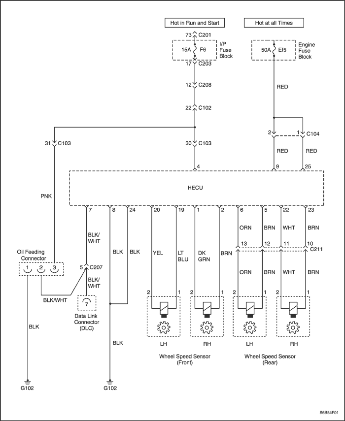
ABS System Circuit (I)
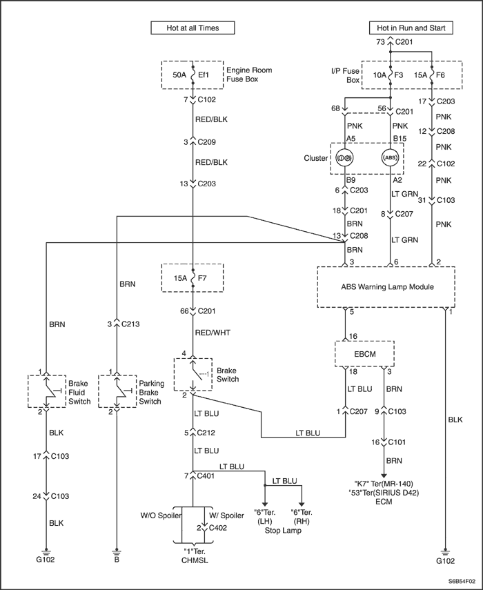
Abs System Circuit (II)
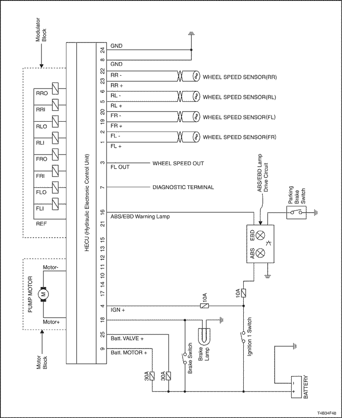
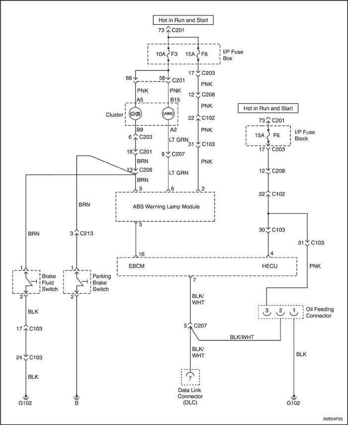
Electrical Schematic
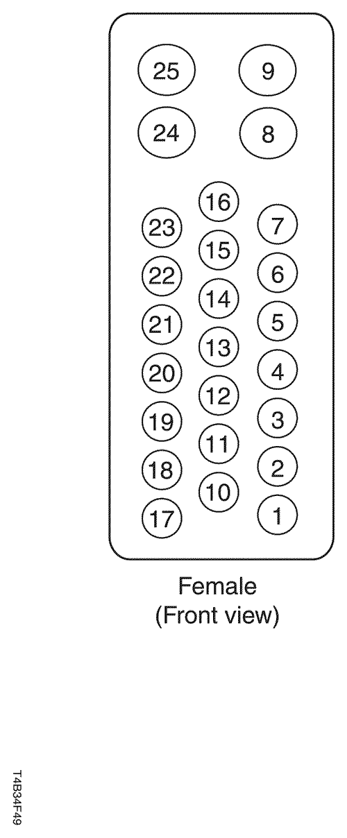
HECU Harness Connector end View and Pin Layout
ABS (Export) Pin Assignments
Pin Location | Circuit Function |
1 | RIGHT FRONT WHEEL SPEED SENSOR |
2 | RIGHT FRONT WHEEL SPEED SENSOR |
3 | WHEEL SPEED SIGNAL TO ECM (ENGINE CONTROL MODULE) |
4 | IGNITION |
. | . |
5 | LEFT FRONT WHEEL SPEED SENSOR |
6 | LEFT FRONT WHEEL SPEED SENSOR |
7 | DIAGNOSTIC |
8 | GROUND (G102) |
9 | BATTERY (HECU MOTOR) |
10 | - |
11 | - |
12 | - |
. | . |
13 | - |
14 | - |
15 | - |
. | . |
16 | ABS/EBD WARNING LAMP OUTPUT |
17 | - |
18 | STOP LAMP SWITCH INPUT |
19 | LEFT FRONT WHEEL SPEED SENSOR |
20 | LEFT FRONT WHEEL SPEED SENSOR |
21 | - |
22 | RIGHT REAR WHEEL SPEED SENSOR |
23 | RIGHT REAR WHEEL SPEED SENSOR |
24 | GROUND (G102) |
25 | BATTERY (SOLENOID VALVE) |
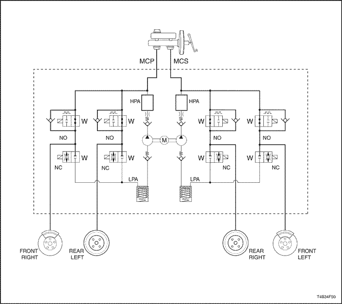
Hydraulic Diagram
MCP : Master Cylinder Primary
MCS : Master Cylinder Secondary
NO : Normal Open Solenoid Valve
NC : Normal Close Solenoid Valve
M : Electric Motor
LPA : Low Pressure Accumulator
HPA : High Pressure Accumulator
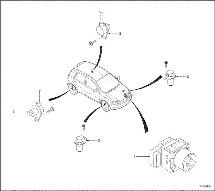
COMPONENT LOCATOR
ABS System
- Hydraulic Electronic Control Unit
- Front Wheel Speed Sensor
- Rear Wheel Speed Sensor
DIAGNOSIS
Diagnostic Trouble Code AND Description
DTC | Decsription | Check Point (Value) |
C1101 | Battery voltage too high | 16V or higher |
C1102 | Battery voltage too low | 9.4V or lower |
C1200 | Left front wheel speed sensor circuit open or shorted | Sensor, Wiring Harness, Connector |
C1201 | Left front wheel speed excessive variation | Sensor, Wiring Harness, Connector, Airgap |
C1202 | Left front wheel speed sensor no signal | Sensor, Wiring Harness, Connector, Airgap, HECU* |
C1203 | Right front wheel speed sensor circuit open or shorted | Sensor, Wiring Harness, Connector |
C1204 | Right front wheel speed excessive variation | Sensor, Wiring Harness, Connector, Airgap |
C1205 | Right front wheel speed sensor no signal | Sensor, Wiring Harness, Connector, Airgap, HECU |
C1206 | Left rear wheel speed sensor circuit open or shorted | Sensor, Wiring Harness, Connector |
C1207 | Left rear wheel speed excessive variation | Sensor, Wiring Harness, Connector, Airgap |
C1208 | Left rear wheel speed sensor no signal | Sensor, Wiring Harness, Connector, Airgap, HECU |
C1209 | Right rear wheel speed sensor circuit open or shorted | Sensor, Wiring Harness, Connector |
C1210 | Right rear wheel speed excessive variation | Sensor, Wiring Harness, Connector, Airgap |
C1211 | Right rear wheel speed sensor no signal | Sensor, Wiring Harness, Connector, Airgap, HECU |
C1604 | HECU internal fault | HECU |
C2112 | Valve relay or fuse failure | Fuse, HECU |
C2402 | Pump motor failure | Motor, Fuse, Connector |
* HECU : Hydraulic Electronic Control Unit
Diagnostic Circuit Check
System Description
The Diagnostic Circuit Check is an organized method of identifying any problems caused by a malfunction in the ABS/DDRP system.
A service technician should begin diagnosis of any ABS/DDRP complaint with the Diagnostic Circuit Check. The Diagnostic Circuit Check directs a service technician to the next logical step when diagnosing a complaint.
Serial Data is transmitted/received by the HECU through terminal 7. The HECU is supplied with constant battery feed voltage through terminals 9 and 25, and switched ignition voltage through terminal 4. The HECU ground is provided through terminal 8 and 24.
Diagnostic Process
Use the following ordered procedure when servicing the ABS/DDRP system.
- Inspect the vehicle for any mechanical conditions related the brake system.
- Brake reservoir fluid level correct.
- Inspect master for fluid for contamination.
- Inspect brake master/modulator for leaks.
- Inspect brake components at all wheels.
- Verify no brake drag exists (brake switch adjustment).
- Verify even brake apply (no pull or lead).
- Inspect for worn/damaged brake pads.
- Inspect for worn/damaged wheel bearings
- Inspect wheel speed sensors/wiring.
- Inspect exciter rings for damage
- Inspect tires for tread depth/wear.
- Road test the vehicle to verify the complaint
- Perform the Diagnostic Circuit Check and proceed to the applicable Diagnostic Trouble Chart as necessary.
- Clear the ABS DTCs (Diagnostic Trouble Codes) after all of the system malfunctions have been corrected.
Diagnostic Circuit Check
| Step | Action | Value(s) | Yes | No |
| 1 | - Connect or install all previously disconnected or removed components if applicable.
- Ignition switch "ON"
- Install the applicable Scan Tool into the DLC and attempt to communicate with the HECU.
Does the Scan Tool communicate with the HECU? | - | Go to Step 2 | Go to Step 4 |
| 2 | Were any DTC(s) stored current or history? | - | Go to Step 3 | Go to Step 7 |
| 3 | - Document Current DTC(s).
- Document History DTC(s).
- Document Enhanced History Data such as
- number of times each DTC set.
- number of times since each DTC first set.
- number of times each DTC set.
- speed when each DTC set.
- other Enhanced Data which may assist with diagnosis.
- Do not clear DTC(s) prior to fully documenting the information from the scan tool.
- Refer to the applicable Diagnostic Trouble Code(s).
| - | Go to the table for the DTC(s) | - |
| 4 | Does the Scan Tool communicate with other Modules on the data line? | - | Go to Step 5 | Go to Step 6 |
| 5 | Go to the no communication with HECU with HECU trouble chart. | - | | System OK |
| 6 | Repair the DLC harness. Replace the DLC harness as needed. | - | System OK | - |
| 7 | - Ignition switch "OFF"
- Wait 10 seconds.
- Ignition switch "ON"
- Observe the amber ABS lamp when the key is turned on.
Did the ABS Warning Lamp and Brake Warning Lamp turn on for 3 seconds and then turn off? (bulb test) | - | Go to Step 8 | Go to Step 9 |
| 8 | System functioning as designed. | - | System OK | - |
| 9 | Did the any lamp stay on? | - | Go to Step 10 | Go to Step 11 |
| 10 | Go to appropriate lamp "ON" trouble chart. | - | - | - |
| 11 | Go to appropriate lamp "INOPERATIVE" trouble chart | - | - | - |
No Communication with HECU
Circuit Description
Serial Data is transmitted/received by the HECU through terminal 7. The HECU is supplied with constant battery feed voltage through terminals 9 and 25, and switched ignition voltage through terminal 4. The HECU ground is provided through terminal 8 and 24.
Diagnostic Aids
Typical causes of no communication with the HECU.
- Poor terminal contact at the HECU.
- Loss of HECU ground to terminal 8 and 24
- Loss of battery voltage at HECU terminals 9 and or 25.
- Loss of ignition voltage at HECU terminal 4.
- Open/grounded data line.
- Data line with high resistance.
No Communication with HECU
| Step | Action | Value(s) | Yes | No |
| 1 | Was the Diagnostic Circuit Check Performed? | - | Go to Step 3 | Go to Step 2 |
| 2 | Perform the Diagnostic Circuit Check. Did you find problem? | - | Go to Step 3 | System OK |
| 3 | - Ignition switch "OFF"
- Disconnect the HECU harness.
- Connect a voltmeter to HECU harness terminal 9 and then to body ground.
Was the voltage within the specified range? | Battery Voltage | Go to Step 5 | Go to Step 4 |
| 4 | Repair the source of low voltage to terminal 9. Inspect for an open fuse, poor terminal contact, or a grounded wire. | - | System OK | - |
| 5 | Connect a voltmeter to HECU harness terminal 25 and then to body ground. Was the voltage within the specified range? | Battery Voltage | Go to Step 7 | Go to Step 6 |
| 6 | Repair the source of low voltage to terminal 25. Inspect for an open fuse, poor terminal contact, or a grounded wire. | - | System OK | - |
| 7 | - Ignition switch "ON"
- Connect a voltmeter to HECU harness terminal 4 and then to body ground.
Was the voltage within the specified range? | Battery Voltage | Go to Step 9 | Go to Step 8 |
| 8 | Repair the source of low voltage to terminal 4. Inspect for an open fuse, poor terminal contact, or a grounded wire. | - | System OK | - |
| 9 | - Ignition switch "OFF"
- Connect a voltmeter to HECU harness terminal 8 and 24 and then to body ground.
Was the voltage within the specified range? | Less than2 ohms | Go to Step 11 | Go to Step 10 |
| 10 | Repair the source of high resistance between terminal 8 and 24 and body ground. Find and check the ground location where the circuit is secured to body ground. | - | System OK | - |
| 11 | - Ignition switch "OFF"
- HECU harness still disconnected from the HECU.
- Connect an ohmmeter to HECU harness terminal 7 and DLC terminal 7.
Was the voltage within the specified range? | Less than2 ohms | Go to Step 13 | Go to Step 12 |
| 12 | Repair the source of high resistance between terminal 7 and DLC terminal 7. | - | System OK | - |
| 13 | - Ignition switch "OFF"
- HECU harness still disconnected.
- Connect an ohmmeter to HECU harness terminal 7 and then to body ground.
Was the voltage within the specified range? | OL(open circuit) | Go to Step 15 | Go to Step 14 |
| 14 | Find and repair the short to ground on the data line. | - | System OK | - |
| 15 | Replace the HECU. | - | System OK | - |
ABS Warning Lamp Inoperative/No DTC Set


Circuit Description
The Hydraulic Electronic Control Unit (HECU) controls the operation of the amber ABS Warning Lamp by means of a lamp driver module contained within the Cluster.
Battery voltage is supplied to the I/P Cluster terminal 11, and HECU terminal 4 when the ignition switch is turned on. HECU terminals 9 and 25 are 'hot at all times'.
The default state is for the Lamp Driver Module to turn ON the amber ABS Warning Lamp, by supplying a ground path through the Lamp Driver Module.
When the HECU commands the ABS lamp off, the HECU will ground the ABS Warning Lamp control circuit. This causes the Lamp Driver Module to open the path to ground for the bulb.
When the ignition switch is turned to the ON position, the HECU turns ON the ABS Warning Lamp for 3 seconds for a bulb check.
Whenever a malfunction is detected within the ABS system, the HECU turns ON the ABS Warning Lamp, notifying the driver that ABS needs to be serviced.
Diagnostic Aids
Typical causes of the ABS warning lamp inoperative with no DTC(s) set.
- Faulty ABS bulb/ loose socket.
- I/P fuse open.
- Faulty Cluster/Lamp Driver Module.
- Faulty HECU.
- Grounded circuit between the HECU and the Cluster.
- Grounded circuit between the HECU and the Cluster.
ABS Warning Lamp Inoperative/No DTC Set
| Step | Action | Value(s) | Yes | No |
| 1 | Was the Diagnostic Circuit Check performed? | - | Go to Step 3 | Go to Step 2 |
| 2 | Perform the Diagnostic Circuit Check. Did you find problem | - | Go to Step 3 | System OK |
| 3 | - Disconnect the HECU harness from the HECU.
- Key on.
Did the amber ABS lamp turn on? | - | Go to Step 4 | Go to Step 5 |
| 4 | Replace the HECU. | - | System OK | - |
| 5 | Check the Cluster fuse. Is the fuse and terminal contact ok? | - | Go to Step 7 | Go to Step 6 |
| 6 | Replace the open fuse and/or repair the loose terminals. Find the short, which caused the fuse to open, if applicable. | - | System OK | - |
| 7 | Remove the amber ABS bulb from the Cluster and inspect for an open bulb filament or poor socket contact? Was the socket and bulb ok? | - | Go to Step 9 | Go to Step 8 |
| 8 | Replace the Bulb/Socket as needed. | - | System OK | - |
| 9 | - Ignition switch "OFF".
- HECU harness still disconnected.
- Remove the Cluster Assembly from the Instrument Panel.
- Disconnect the Cluster harness connector from the Cluster Assembly.
- Ignition switch "ON".
- Connect a voltmeter to the terminal A5 of the Cluster harness and then to body ground.
Was the voltage within the specified range? | Battery Voltage | Go to Step 11 | Go to Step 10 |
| 10 | Find and repair the source of low voltage on the cluster voltage supply terminal. | - | System OK | - |
| 11 | - Ignition switch "OFF".
- Disconnect the Cluster harness connector from the Cluster Assembly.
- Connect an ohmmeter between the Cluster harness terminal A2 and ABS Warning Lamp Module terminal 6.
Was the resistance within the specified range? | Less than2 ohms | Go to Step 13 | Go to Step 12 |
| 12 | Repair the open or high resistance between the cluster and the ABS Warning Lamp Module. | - | System OK | - |
| 13 | - Ignition switch "OFF".
- ABS Warning Lamp Module harness and HECU harness still disconnected.
- Connect an ohmmeter to HECU harness terminal 16 and then to body ground.
Was the resistance within the specified range? | OL(open circuit) | Go to Step 15 | Go to Step 14 |
| 14 | Find the repair the short to ground between the Cluster harness and the HECU harness. | - | System OK | - |
| 15 | Replace the ABS Warning Lamp Module. Is the repair complete? | - | System OK | Go to Step 16 |
| 17 | Replace the Cluster Assembly. | - | System OK | - |
ABS Warning Lamp On/No DTC Set
Circuit Description
The Hydraulic Electronic Control Unit (HECU) controls the operation of the amber ABS Warning Lamp by means of a lamp driver module contained within the Cluster.
Battery voltage is supplied to the I/P Cluster terminal 11, and HECU terminal 4 when the ignition switch is turned on. HECU terminals 9 and 25 are `hot at all times'.
The default state is for the Lamp Driver Module to turn ON the amber ABS lamp, by supplying a ground path through the Lamp Driver Module.
When the HECU commands the ABS lamp off, the HECU will ground the ABS Warning Lamp control circuit. This causes the Lamp Driver Module to open the path to ground for the bulb.
When the ignition switch is turned to the ON position, the HECU turns ON the ABS Warning Lamp for 3 seconds for a bulb check.
Whenever a malfunction is detected within the ABS system, the HECU turns ON the ABS Warning Lamp, notifying the driver that ABS needs to be serviced.
Diagnostic Aids
Typical causes of the ABS warning lamp on with no DTC(s) set.
- Grounded circuit between the Cluster and the HECU.
- Faulty Cluster/Lamp Driver Module.
- Faulty HECU.
ABS Warning Lamp On/No DTC Set
| Step | Action | Value(s) | Yes | No |
| 1 | Was the Diagnostic Circuit Check performed? | - | Go to Step 3 | Go to Step 2 |
| 2 | Perform the Diagnostic Circuit Check. Did you find problem? | - | Go to Step 3 | System OK |
| 3 | - Ignition switch "OFF".
- Disconnect the HECU harness from the HECU.
- Ignition switch "ON".
- Connect a fused jumper wire between terminal 16 of the HECU harness and body ground.
Did the amber ABS lamp turn off? | - | Go to Step 4 | Go to Step 5 |
| 4 | Replace the HECU. | - | System OK | - |
| 5 | - Ignition switch "OFF".
- Remove the Cluster Assembly from the I/P.
- Disconnect the Cluster harness connector from the Cluster Assembly.
- Disconnect the ABS Warning Lamp Module harness connector from the ABS Warning Lamp Module.
- Connect an ohmmeter to cluster harness terminal A2 and then to body ground.
Was the resistance within the specific range? | OL(open circuit) | Go to Step 7 | Go to Step 6 |
| 6 | Find the repair the short to ground between the Cluster harness and the ABS Warning Lamp Module harness. | - | System OK | - |
| 7 | - Ignition switch "OFF".
- Disconnect the HECU harness from the HECU.
- Disconnect the ABS Warning Lamp Module harness from the ABS Warning Lamp Module.
- Connect an ohmmeter to terminal 5 of the ABS Warning Lamp Module harness and then to HECU harness terminal 16.
Was the resistance within the specific range? | Less than2 ohms | Go to Step 9 | Go to Step 8 |
| 8 | Repair the open or high resistance between the ABS Warning Lamp Module and the HECU. | - | System OK | - |
| 9 | Replace the ABS Warning Lamp Module. Is the repair complete? | - | System OK | Go to Step 10 |
| 10 | Replace the Cluster Assembly. | - | System OK | - |
Brake Warning Lamp On
Circuit Description
The Hydraulic Electronic Control Unit (HECU) controls the operation of the Brake Warning Lamp by means of a lamp driver module contained within the Cluster.
Battery voltage is supplied to the I/P Cluster terminal A5, and HECU terminal 4 when the ignition switch is turned on HECU terminals 9 and 25 are `hot at all times'
The default state is for the Lamp Driver Module to turn ON the Brake Warning Lamp, by supplying a ground path through the Lamp Driver Module.
When the HECU commands the Brake Warning Lamp off, the HECU will ground the ABS Warning Lamp control circuit. This causes the Lamp Driver Module to open the path to ground for the bulb.
When the ignition switch is turned to the ON position, the HECU turns ON the Brake Warning Lamp for 3 seconds for a bulb check.
Whenever a malfunction is detected within the general brake system or MANDO MGH25 ABS system, the HECU may turn ON the Brake Warning Lamp, notifying the driver that either Brake System or MGH25 needs to be serviced.
Diagnostic Aids
Typical causes of the Brake Warning Lamp on with no DTC(s) set
- Faulty Emergency brake switches.
- Low brakes fluid level or faulty brake fluid switch.
- DDPR is disabled due to the following fault conditions in MGH25 ABS system.
- Two Wheel Speed Sensors inoperative on same axle.
- Battery 2(Motor Input) short to ground.
- Battery 1(ECU Input) Open or short to ground.
- Motor ground open or short to battery.
- ECU ground open or short to battery.
- Ignition open or short to ground.
- Grounded circuit between the Cluster and the HECU.
- Faulty Cluster/Lamp Driver Module.
- Faulty HECU.
Brake Warning Lamp On
| Step | Action | Value(s) | Yes | No |
| 1 | Was the Diagnostic Circuit Check performed? | - | Go to Step 3 | Go to Step 2 |
| 2 | Perform the Diagnostic Circuit Check. Did you find problem? | - | Go to Step 3 | System OK |
| 3 | - Observe ABS Warning Lamp.
Does ABS Warning Lamp ON also? | - | Go to Step 5 | Go to Step 4 |
| 4 | Possibility of general brake system failure. Repair the brake system. | - | System OK | - |
| 5 | - Connect Scan Tool and retrieve DTC.
Did DTC exist? | - | Go to Step 6 | Go to Step 7 |
| 6 | Go to appropriate DTC diagnostic section. | - | System OK | - |
| 7 | - Ignition switch "OFF".
- Disconnect the HECU harness from the HECU.
- Ignition switch "ON".
- Connect a fused jumper wire between terminal 16 of the HECU harness and body ground.
Did the Brake Warning Lamp turn off? | - | Go to Step 8 | Go to Step 9 |
| 8 | Replace the HECU. | - | System OK | - |
| 9 | - Ignition switch "OFF".
- Remove the Cluster Assembly from the I/P.
- Disconnect the white Cluster harness connector from the Cluster Assembly.
- Disconnect the ABS Warning Lamp Module harness connector from the ABS Warning Lamp Module.
- Connect an ohmmeter to cluster harness B9 and then to body ground.
Was the resistance within the specific range? | OL(open circuit) | Go to Step 11 | Go to Step 10 |
| 10 | Find the repair the short to ground between the Cluster harness and the ABS Warning Lamp Module harness. | - | System OK | - |
| 11 | - Ignition switch "OFF".
- ABS Warning Lamp Module harness and HECU harness still disconnected
- Connect an ohmmeter to terminal 5 of the ABS Warning Lamp Module harness and then to HECU harness terminal 16.
Was the resistance within the specific range? | Less than2 ohms | Go to Step 13 | Go to Step 12 |
| 12 | Repair the open or high resistance between the ABS Warning Lamp Module and the HECU. | - | System OK | - |
| 13 | Replace the ABS Warning Lamp Module. Is the repair complete? | - | System OK | Go to Step 14 |
| 14 | Replace the Cluster Assembly. | - | System OK | - |
Brake Warning Lamp Inoperative/No DTC Set
Circuit Description
The Hydraulic Electronic Control Unit (HECU) controls the operation of the red Brake Warning Lamp by means of a lamp driver module contained within the Cluster.
Battery voltage is supplied to the I/P Cluster terminal 11, and HECU terminal 4 when the ignition switch is turned on HECU terminals 9 and 25 are `hot at all times'
When the HECU commands the Brake Warning lamp off, the HECU will ground the Brake Warning Lamp control circuit. This causes the Lamp Driver Module to open the path to ground for the bulb.
When the ignition switch is turned to the ON position, the HECU turns ON the Brake Warning Lamp for 3 seconds for a bulb check.
Whenever a malfunction is detected within the General Brake system or DDRP, the HECU turns ON the Brake Warning Lamp, notifying the driver that Brake System or DDRP needs to be serviced.
Diagnostic Aids
Typical causes of the Brake Warning Lamp inoperative with no DTC(s) set.
- Faulty bulb/ loose socket.
- I/P fuse open.
- Faulty Cluster/Lamp Driver Module.
- Faulty HECU.
- Grounded circuit between the HECU and the Cluster.
Brake Warning Lamp Inoperative/No DTC Set
| Step | Action | Value(s) | Yes | No |
| 1 | Was the Diagnostic Circuit Check performed? | - | Go to Step 3 | Go to Step 2 |
| 2 | Perform the Diagnostic Circuit Check. Did you find problem? | - | Go to Step 3 | System OK |
| 3 | - Disconnect the HECU harness from the HECU.
- Ignition switch "ON".
Did the Brake Warning Lamp turn on? | - | Go to Step 4 | Go to Step 5 |
| 4 | Replace the HECU. | - | System OK | - |
| 5 | Check the Cluster fuse. Is the fuse and terminal contact ok? | - | Go to Step 7 | Go to Step 6 |
| 6 | Replace the open fuse and/or repair the loose terminals. Find the short, which caused the fuse to open, if applicable. | - | System OK | - |
| 7 | Remove the Brake Warning Lamp bulb from the Cluster and inspect for an open bulb filament or poor socket contact? Was the socket and bulb ok? | - | Go to Step 9 | Go to Step 8 |
| 8 | Replace the Bulb/Socket as needed. | - | System OK | - |
| 9 | - Ignition switch "OFF".
- HECU harness still disconnected.
- Remove the Cluster Assembly from the Instrument Panel.
- Disconnect the white Cluster harness connector from the Cluster Assembly.
- Ignition switch "ON".
- Connect a voltmeter to the terminal A5 of the Cluster harness and then to body ground.
Was the voltage within the specified range? | Battery Voltage | Go to Step 11 | Go to Step 10 |
| 10 | Find and repair the source of low voltage on the cluster voltage supply terminal. | - | System OK | - |
| 11 | - Ignition switch "OFF".
- Disconnect the White Cluster harness connector from the Cluster Assembly.
- Connect an ohmmeter between the Cluster harness terminal B9 and ABS Warning Lamp Module harness terminal E.
Was the resistance within the specific range? | Less than2 ohms | Go to Step 13 | Go to Step 12 |
| 12 | Repair the open or high resistance between the cluster and the ABS Warning Lamp Module. | - | System OK | - |
| 13 | - Ignition switch "OFF".
- ABS Warning Lamp Module harness and HECU harness still disconnected
- Connect an ohmmeter to HECU harness terminal 16 and then to body ground..
Was the resistance within the specific range? | OL(open circuit) | Go to Step 15 | Go to Step 14 |
| 14 | Find the repair the short to ground between the ABS Warning Lamp Module harness and the HECU harness | - | System OK | - |
| 15 | Replace the ABS Warning Lamp Module. Is the repair complete? | - | System OK | Go to Step 16 |
| 16 | Replace the Cluster Assembly. | - | System OK | - |