C1101 Battery Voltage Too High
Circuit Description
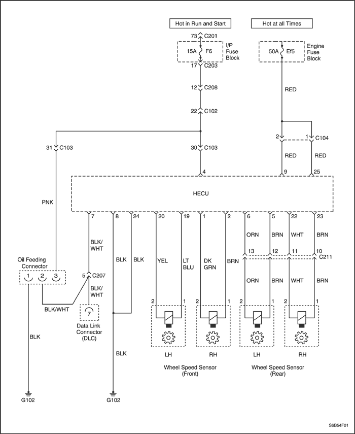
This circuit is used to monitor the voltage level available to the HECU. If the voltage rises above a certain level, damage to the system may occur.
Conditions for Setting the DTC
DTC C1101 can only be set if the vehicles speed is greater than 8kph (5mph), if the voltage supplied to terminals 9 and/or 25 is greater than 17 volts for 1 second.
Action Taken When the DTC Sets
- The solenoid relay opens, removing voltage from the solenoids and pump motor.
- DTC C1101 is stored.
- ABS disabled, ABS Warning Lamp turns on.
Conditions for Clearing the DTC
- If the conditions that set DTC C1101 is no longer present, the DTC may be cleared by using the proper scan tool.
- The DTC that has not occurred in 100 drive cycles will be cleared from history data.
Diagnostic Aids
Typical causes for DTC C1101 to set.
- Charging system malfunction.
- Poor connection.
- HECU malfunction.
C1101 Battery Voltage Too High
| Step | Action | Value(s) | Yes | No |
| 1 | Was the Diagnostic Circuit Check Completed? | - | Go to Step 3 | Go to Step 2 |
| 2 | Perform the Diagnostic Circuit Check. Did you find any problem? | - | Go to Step 3 | System OK |
| 3 | - Disconnect the HECU connector.
- Ignition switch "ON".
- Check the voltage between the terminal 4 and 8 of the HECU connector.
- Check the voltage between the terminal 4 and 24 of the HECU connector.
Were the voltages within the specified range? | 9.4~17V | Go to Step 4 | Go to Step 5 |
| 4 | Replace the HECU. Check again the dDiagnostic circuit. Did you find any problem? | - | Go to Step 1 | System OK |
| 5 | Check the battery voltae between the terminal (+) and (-) of the battery. Was the voltage within the specified range? | 9.4~17V | Go to Step 7 | Go to Step 6 |
| 6 | Replace the Battery. | - | Go to Step 1 | - |
| 7 | Check the resistance between the terminal 4 of the HECU connector and the terminal (+) of the battery. Was the resistance within the specified range? | less than 1 Ω | Go to Step 9 | Go to Step 8 |
| 8 | - Check the both terminals mentioned step 7.
- Repair the terminals, as needed.
- Check the HECU connector and wiring harness.
- Repair or replace the wiring harness, as needed.
| - | - | - |
| 9 | Check the resistance between the terminal 8, 24 and G104. Was the resistance specified range? | less than 1 Ω | Go to Step 11 | Go to Step 10 |
| 10 | Repair or replace the HECU connector or G102. | - | Go to Step 1 | - |
| 11 | - Connect a voltmeter to the positive and negative terminal of the battery.
- Turn OFF all accessories.
- Start the engine.
- Monitor the voltage on the meter with the engine running at 2000 rpm for several seconds.
- And also check the voltage between the terminal 4 and 8. And also check the voltage between the terminal 4 and 24. For all the volts in the step 11.
Was the within specified range? | less than 17V | Go to Step 1 | Go to Step 12 |
| 12 | Repair the Alternator. | - | Go to Step 1 | - |
C1102 Battery Voltage Too Low
Circuit Description
This circuit is used to monitor the voltage level available to the HECU. If the voltage drops below a certain level, full performance of the system cannot be guaranteed. During ABS operation, there are several current requirements that will cause battery voltage to drop. Because of this, voltage is monitored prior to ABS operation to indicate good charging system condition and also during ABS operation when voltage may drop significantly.
Conditions for Setting the DTC
C1102 can only be set if the vehicles speed is greater than 8kph (5mph), if the ignition voltage to terminal 4 and battery voltage to terminal 9 and 25 are less than 10.5 volts during non ABS or initialization. The DTC will also set if the ignition voltage is below 10.5 volts and the battery voltage is below 9.0 volts during ABS.
Action Taken When the DTC Sets
- The solenoid relay opens, removing voltage from the solenoids and pump motor.
- DTC C1102 is stored.
- ABS disabled, ABS Warning Lamp turns on.
Conditions for Clearing the DTC
- If the conditions that set DTC C1102 are no longer present, the DTC may be cleared by using the proper scan tool.
- The DTC that has not occurred in 100 drive cycles will be cleared from history data.
Diagnostic Aids
Typical causes for DTC C1102 to set.
- Weak or discharged battery.
- Poor battery terminal contact.
- Excessive battery draws from factory or after-market equipment (parasitic load).
- Poor battery ground at block or chassis.
- Poor terminal contact at HECU.
- Poor HECU ground connection.
- Charging system malfunction (generator).
- Thoroughly inspect the wiring and the connectors. Failure to inspect the wiring and the connectors carefully and fully can cause replacement of parts without repairing the malfunction.
C1102 Battery Voltage Too Low
| Step | Action | Value(s) | Yes | No |
| 1 | Was the Diagnostic Circuit Check Completed? | - | Go to Step 3 | Go to Step 2 |
| 2 | Perform the Diagnostic Circuit Check. Did you find any problem? | - | Go to Step 3 | System OK |
| 3 | - Disconnect the HECU connector.
- Ignition switch "ON".
- Check the voltage between the terminal 4 and 8 of the HECU connector.
- Check the voltage between the terminal 4 and 24 of the HECU connector.
Were the voltages within the specified range? | 9.4~17V | Go to Step 4 | Go to Step 5 |
| 4 | Replace the HECU. Check again the dDiagnostic circuit. Did you find any problem? | - | Go to Step 1 | System OK |
| 5 | Check the battery voltae between the terminal (+) and (-) of the battery. Was the voltage within the specified range? | 9.4~17V | Go to Step 7 | Go to Step 6 |
| 6 | Replace the Battery. | - | Go to Step 1 | - |
| 7 | Check the resistance between the terminal 4 of the HECU connector and the terminal (+) of the battery. Was the resistance within the specified range? | less than 1 Ω | Go to Step 9 | Go to Step 8 |
| 8 | - Check the both terminals mentioned step 7.
- Repair the terminals, as needed.
- Check the HECU connector and wiring harness.
- Repair or replace the wiring harness, as needed.
| - | - | - |
| 9 | Check the resistance between the terminal 8, 24 and G102. Was the resistance specified range? | less than 1 Ω | Go to Step 11 | Go to Step 10 |
| 10 | Repair or replace the HECU connector or G102. | - | Go to Step 1 | - |
| 11 | - Connect a voltmeter to the positive and negative terminal of the battery.
- Turn OFF all accessories.
- Start the engine.
- Monitor the voltage on the meter with the enginer running at 2000 rpm for several seconds.
- And also check the voltage between the terminal 4 and 8. And also check the voltage between the terminal 4 and 24. For all the volts int he step 11.
Was the within specified range? | less than 17V | Go to Step 1 | Go to Step 12 |
| 12 | Repair the Alternator. | - | Go to Step 1 | - |
C1200 Left Front Wheel Speed Sensor Circuit Open or Shorted
Circuit Description
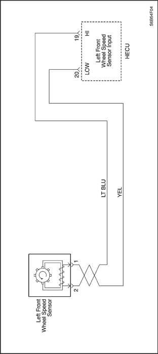
As the wheel is rotated, the speed sensor produces an AC voltage that increases with wheel speed. The HECU uses the frequency of the AC signal to calculate wheel speed. The speed sensor is connected to the HECU by a "twisted pair" of wires. Twisting reduces noise susceptibility that may cause a DTC to set.
Conditions for Setting the DTC
DTC C1200 can be set anytime the key is on and the HECU has detected an open, short to ground or a short to battery on the left front wheel speed circuit.
Action Taken When the DTC Sets
- The solenoid relay opens, removing power to the pump motor and solenoids.
- DTC C1200 is stored.
- ABS disabled, ABS Warning Lamp turns on.
Conditions for Clearing the DTC
- If the conditions that set DTC C1200 are no longer present, the DTC may be cleared by using the proper scan tool.
- The DTC that has not occurred in 100 drive cycles will be cleared from history data.
Diagnostic Aids
Thoroughly inspect the wiring and connectors when diagnosing intermittent DTC(s). This will include the following.
- Removal of the protective conduit and inspection for wiring for damage, shorts and contamination.
- Inspection for improperly formed and/or damaged terminals.
- Checking terminal contact (retention force) by using a spare male/female terminal.
- Removal of the terminals from the connectors to check for proper terminal to wire crimp.
If the drivers comments reflect that the ABS Warning Lamp is on only during moist environmental changes (rain, snow, vehicle wash), all wheel speed sensor circuitry should be thoroughly inspected for signs of water intrusion. If the DTC is not current, simulate the effects of water intrusion. Use the following procedure. Spray the suspected area with a 5 percent salt-water solution. Then test-drive the vehicle over various road surfaces such as (bumps, turns, etc) above 24 kph (15 mph). If the DTC sets then replace the suspected harness and or sensor.
When measuring wheel speed sensor resistance insure the vehicle is at room temperature, since resistance will increase with temperature
Failure to perform the previous steps carefully and fully can result in misdiagnosis, unnecessary component replacement and reoccurrence of DTC C1200.
C1200 Left Front Wheel Speed Sensor Circuit Open or Shorted
| Step | Action | Value(s) | Yes | No |
| 1 | Was the diagnostic circuit check performed? | - | Go to Step 3 | Go to Step 2 |
| 2 | Perform the Diagnostic Circuit Check. Did you find problem? | - | Go to Step 3 | System OK |
| 3 | - Ignition switch "OFF".
- Inspect the left front wheel speed sensor, jumper harness and the toothed ring for physical damage.
Is any physical damage noted? | - | Go to Step 4 | Go to Step 5 |
| 4 | Repair the damage to the left front wheel speed sensor, jumper harness and/or toothed ring. | - | System OK | - |
| 5 | Test-drive vehicle at various speeds and over various road surfaces. Did C1200 reset? | - | Go to Step 7 | Go to Step 6 |
| 6 | DTC C1200 is intermittent. Refer to Diagnostic Aids. | - | System OK | - |
| 7 | - Ignition switch "OFF", vehicle in park.
- Raise and suitably support the vehicle.
- Disconnect the left front jumper harness from the Left Front Wheel Speed Sensor.
- Connect an ohmmeter to terminals 2 and 1 of the Left Front Wheel Speed Sensor.
Is the resistance with in specified range?. | 800-1600 Ohms (Resistance will vary with temperature) | Go to Step 9 | Go to Step 8 |
| 8 | Replace the left front wheel speed sensor. | - | System OK | - |
| 9 | - Left front jumper harness still disconnected from the speed sensor.
- Connect an ohmmeter to terminal 2 of the left front wheel speed sensor and then to body ground.
Is the resistance within the specified range? | OL(open circuit) | Go to Step 10 | Go to Step 8 |
| 10 | - Disconnect the HECU harness from the HECU.
- Disconnect the left front jumper harness from the ABS body harness.
- Connect an ohmmeter to HECU harness terminal 20 and then the left front wheel speed sensor terminal 2.
Is the resistance within the specified range? | Less than2 ohms | Go to Step 12 | Go to Step 11 |
| 11 | Repair the open or high resistance between terminals 20 and 2. | - | System OK | - |
| 12 | - HECU harness still disconnected from the HECU.
- Left front jumper harness still disconnected from the ABS body harness.
- Connect an ohmmeter to HECU harness terminal 19 and then to left front wheel speed sensor terminal 1.
Is the resistance within the specified range? | Less than2 ohms | Go to Step 4 | Go to Step 13 |
| 13 | Repair the open or high resistance between terminals 19 and 1. | - | System OK | - |
| 14 | - HECU harness still disconnected from the HECU.
- Left front jumper harness still disconnected from the ABS body harness.
- Connect a voltmeter to HECU harness terminal 20 and then to body ground.
Is the voltage within the specified range? | Less than 1volt | Go to Step 16 | Go to Step 15 |
| 15 | Repair the source open or high resistance between terminals 20 and 2. | - | System OK | - |
| 16 | - HECU harness still disconnected from the HECU.
- Left front jumper harness still disconnected from the ABS body harness.
- Connect a voltmeter to HECU harness terminal 19 and then to body ground.
Is the voltage within the specified range? | Less than 1volt | Go to Step 18 | Go to Step 17 |
| 17 | Repair the short to voltage between terminals 19 and 1. | - | System OK | - |
| 18 | - HECU harness still disconnected from the HECU.
- Left front jumper harness still disconnected from the ABS body harness.
- Connect an ohmmeter to HECU harness terminal 20 and then to body ground.
Is the resistance within the specified range? | OL(open circuit) | Go to Step 20 | Go to Step 19 |
| 19 | Repair the short to ground between terminals 20 and 2. | - | System OK | - |
| 20 | - HECU harness still disconnected from the HECU.
- Left front jumper harness still disconnected from the ABS body harness.
- Connect an ohmmeter to HECU harness terminal 19 and then to body ground.
- Left front jumper harness still disconnected from the ABS body harness. Connect an ohmmeter to HECU harness terminal 19 and then to body ground. Is the resistance within the specified range?
Is the resistance within the specified range? | OL(open circuit) | Go to Step 22 | Go to Step 21 |
| 21 | Repair the short to ground between terminals 19 and 1. | - | System OK | - |
| 22 | - HECU harness still disconnected from the HECU.
- Connect an ohmmeter to HECU harness terminal 19 and 20.
Is the resistance within the specified range? | OL(open circuit) | Go to Step 24 | Go to Step 23 |
| 23 | Repair the short between the 2 circuits. | - | System OK | - |
| 24 | - Replace the Left Front Wheel Speed Sensor Jumper Harness.
- Test-drive the vehicle at various speeds and various road surfaces.
Did C1200 reset? | - | Go to Step 25 | System OK |
| 25 | Replace the HECU. | - | System OK | - |
C1201 Left Front Wheel Speed Excessive Variation
Circuit Description
As the wheel is rotated, the speed sensor produces an AC voltage that increases with wheel speed. The HECU uses the frequency of the AC signal to calculate wheel speed. The speed sensor is connected to the HECU by a "twisted pair" of wires. Twisting reduces noise susceptibility that may cause a DTC to set.
Conditions for Setting the DTC
All of the following must be true for C1201 to set.
- C1200 or C1203 or C1206 or C1209 not current.
- Brake switch off.
- The left front wheel speed is accelerating or decelerating beyond reasonable limits.
Action Taken When the DTC Sets
- The solenoid relay opens, removing power from the pump motor and solenoids.
- DTC C1201 is stored.
- ABS disabled, ABS Warning Lamp turns on.
Conditions for Clearing the DTC
- If the conditions that set DTC C1201 are no longer present, the DTC may be cleared by using the proper scan tool.
- The DTC that has not occurred in 100 drive cycles will be cleared from history data.
Diagnostic Aids
Thoroughly inspect the wiring and connectors when diagnosing intermittent DTC(s). This will include the following.
- Removal of the protective conduit and inspection for wiring for damage, shorts and contamination.
- Inspection for improperly formed and/or damaged terminals.
- Checking terminal contact (retention force) by using a spare male/female terminal.
- Removal of the terminals from the connectors to check for proper terminal to wire crimp.
If the drivers comments reflect that the ABS Warning Lamp is on only during moist environmental changes (rain, snow, vehicle wash), all wheel speed sensor circuitry should be thoroughly inspected for signs of water intrusion. If the DTC is not current, simulate the effects of water intrusion. Use the following procedure. Spray the suspected area with a 5 percent salt-water solution. Then test-drive the vehicle over various road surfaces such as (bumps, turns, etc) above 24 kph (15 mph). If the DTC sets then replace the suspected harness and/or sensor.
A careful visual inspection of the toothed ring for damaged such as cracks and tooth damage should be performed. If the DTC sets at the same speed every drive cycle, the toothed ring is most likely damaged.
Failure to perform the previous steps carefully and fully can result in misdiagnosis, unnecessary component replacement and reoccurrence of DTC C1201.
C1201 Left Front Wheel Speed Excessive Variation
| Step | Action | Value(s) | Yes | No |
| 1 | Was the Diagnostic Circuit Check Completed? | - | Go to Step 3 | Go to Step 2 |
| 2 | Perform the Diagnostic Circuit Check prior to performing DTC C1201 trouble chart. Did you find problem? | - | Go to Step 3 | System OK |
| 3 | Was C1200 set as a current or history DTC? | - | Go to Step 4 | Go to Step 5 |
| 4 | Perform C1200 diagnostic chart prior to performing DTC C1201 trouble chart. | - | System OK | - |
| 5 | - Ignition switch "OFF".
- Inspect the left front wheel speed sensor and the jumper harness for damage.
- Perform a complete and thorough inspection of the left front toothed ring for damage. (cracks, missing teeth, looseness)
Is any physical damage noted? | - | Go to Step 6 | Go to Step 7 |
| 6 | Repair the damage to the left front wheel speed sensor, jumper harness and/or the toothed ring. | - | System OK | - |
| 7 | - Vehicle in park.
- Connect a Scan Tool and select data list.
- Monitor the wheel speed sensors.
- Start the vehicle, and monitor wheel speed sensors with engine running but vehicle not moving.
- Lightly depress the accelerator pedal to increase engine idle speed.
Did C1201 reset or did the left front wheel speed read above 0 mph when the vehicle was in park with the engine running. | - | Go to Step 8 | Go to Step 9 |
| 8 | The cause of C1201 is ignition noise coupled onto the Left Front Speed Sensor circuits. Inspect the routing of the left front ABS body harness and/or jumper harness for potential ignition noise sources such as spark plug wires. Reroute wiring as needed. | - | System OK | - |
| 9 | - Scan tool still connected.
- Monitor the wheel speed sensors.
- Test-drives the vehicle up to the maximum-posted speed limit, and slowly decelerates to zero. Do this several times.
Did C1201 reset or did the left front wheel speed vary more than 5 kph (3 mph) when compared to any one of the other wheels during the drive? | - | Go to Step 11 | Go to Step 10 |
| 10 | DTC C1201 is intermittent, refer to Diagnostic Aids. | - | System OK | - |
| 11 | - Vehicle in park, Ignition switch "OFF".
- Raise and suitably support the vehicle.
- Disconnect the left front jumper harness from the Left Front Wheel Speed sensor.
- Connect an ohmmeter to terminals 2 and 1 of the Left Front Wheel Speed sensor.
Is the resistance within the specified range? | 800-1600 Ohms (Resistance will vary with temperature) | Go to Step 13 | Go to Step 12 |
| 12 | Replace the left front wheel speed sensor. | - | System OK | - |
| 13 | - Speed sensor still disconnected from the jumper harness.
- Connect a voltmeter to terminals 2 and 1 of the left front speed sensor.
- Select the AC milli-volt scale.
- Spin the left front wheel while observing the voltage on the meter.
Is the AC voltage within the specified range? | At least 100mV | Go to Step 14 | Go to Step 12 |
| 14 | - Disconnect the HECU harness from the HECU.
- Disconnect the left front jumper harness from the ABS body harness.
- Connect an ohmmeter to HECU harness terminal 20 and then to ABS body harness terminal 2.
Is the resistance within the specified range? | Less than2 ohms | Go to Step 16 | Go to Step 15 |
| 15 | Repair the source open or high resistance between terminals 20 and 2. | - | System OK | - |
| 16 | - HECU harness still disconnected from the HECU.
- Jumper harness still disconnected from the body harness.
- Connect an ohmmeter to HECU harness terminal 19 and then to ABS body harness terminal 1.
Is the resistance within the specified range? | Less than2 ohms | Go to Step 18 | Go to Step 17 |
| 17 | Repair the open or high resistance between terminals 19 and 1. | - | System OK | - |
| 18 | - HECU harness still disconnected from the HECU.
- Jumper harness still disconnected from the body harness.
- Connect an ohmmeter between HECU harness terminals 20 and 19.
Is the resistance within the specified range? | OL(open circuit) | Go to Step 20 | Go to Step 19 |
| 19 | Repair the short between the 2 wires. | - | System OK | - |
| 20 | - Replace the left front jumper harness.
- Test-drive the vehicle at various speeds and road surfaces.
Did C1201 reset? | - | Go to Step 20 | System OK |
| 21 | Replace the HECU. | - | System OK | - |
C1202 Left Front Wheel Speed Sensor No Signal


Circuit Description
As the wheel is rotated, the speed sensor produces an AC voltage that increases with wheel speed. The HECU uses the frequency of the AC signal to calculate wheel speed. The speed sensor is connected to the HECU by a "twisted pair"of wires. Twisting reduces noise susceptibility that may cause a DTC to set.
Conditions for Setting the DTC
All of the following must be true for C1202 to set.
- C1200 or C1203 or C1206 or C1209 not current
- ABS not active.
- Brake switch off.
The left front wheel speed equals 0, and all of the remaining Wheel Speed Sensors are greater than 8 km/hr (5 mph) for at least 2.5 seconds.
Action Taken When the DTC Sets
- The solenoid relay opens, removing power from the pump motor and solenoids.
- DTC C1202 is stored.
- ABS disabled, ABS Warning Lamp turns on.
Conditions for Clearing the DTC
- If the conditions that set DTC C1202 are no longer present, the DTC may be cleared by using the proper scan tool.
- The DTC that has not occurred in 100 drive cycles will be cleared from history data.
Diagnostic Aids
Thoroughly inspect the wiring and connectors when diagnosing intermittent DTC(s). This will include the following.
- Removal of the protective conduit and inspection of wiring for damage, shorts and contamination.
- Inspection for improperly formed and/or damaged terminals.
- Checking terminal contact (retention force) by using a spare male/female terminal.
- Removal of the terminals from the connectors to check for proper terminal to wire crimp.
If the drivers comments reflect that the ABS warning lamp is on only during moist environmental changes (rain, snow, vehicle wash), all wheel speed sensor circuitry should be thoroughly inspected for signs of water intrusion. If the DTC is not current, simulate the effects of water intrusion. Use the following procedure. Spray the suspected area with a 5 percent salt-water solution. Then test-drive the vehicle over various road surfaces such as (bumps, turns, etc) above 24 kph (15 mph). If the DTC sets then replace the suspected harness and/or sensor.
When measuring wheel speed sensor resistance insures the vehicle is at room temperature, since resistance will increase with temperature.
Failure to perform the previous steps carefully and fully can result in misdiagnosis, unnecessary component replacement and reoccurrence of DTC C1202.
C1202 Left Front Wheel Speed Sensor No Signal
| Step | Action | Value(s) | Yes | No |
| 1 | Was the Diagnostic Circuit Check Completed? | - | Go to Step 3 | Go to Step 2 |
| 2 | Perform the Diagnostic Circuit Check prior to performing this trouble tree. Did you find problem? | - | Go to Step 3 | System OK |
| 3 | - Ignition switch "OFF".
- Inspect the left front wheel speed sensor, jumper harness and toothed ring for physical damage.
Is any physical damage noted? | - | Go to Step 4 | Go to Step 5 |
| 4 | Repair the damage to the left front wheel speed sensor, jumper harness and/or toothed ring. Check the Airgap. | 0.2~0.8mm | System OK | - |
| 5 | Was DTC C1200 set as a current or history code? | - | Go to Step 6 | Go to Step 7 |
| 6 | Perform diagnostics for DTC C1200 prior to performing this table. | - | System OK | - |
| 7 | - Connect a Scan Tool and select data list.
- Monitor the wheel speed sensors.
- Test-drives vehicle above 24 kph (15 mph) and slowly decelerates to zero, do this several times.
Did C1202 reset or did the left front wheel speed suddenly drop to zero prior to the vehicle coming to a complete stop? | - | Go to Step 9 | Go to Step 8 |
| 8 | DTC C1202 is intermittent. Refer to diagnostic aids. | - | System OK | - |
| 9 | - Ignition switch "OFF".
- Raise and suitably support the vehicle.
- Disconnect the HECU harness from the HECU.
- Connect a voltmeter to HECU harness terminals 19 and 20.
- Select the AC mill volt scale.
- Spin the left front wheel while observing the voltmeter. (voltage should increase as wheel speed increases)
Is the AC voltage within the specified range? | At least 100mV | Go to Step 10 | Go to Step 11 |
| 10 | Replace the HECU. | - | System OK | - |
| 11 | - Disconnect the left front jumper harness from the Left Front Wheel Speed Sensor.
- Connect an ohmmeter to terminals 2 and 1 of the Left Front Wheel Speed Sensor.
Is the resistance within the specified range? | 800-1600 Ohms (Resistance will vary with temperature) | Go to Step 13 | Go to Step 12 |
| 12 | Replace the left front wheel speed sensor. | - | System OK | - |
| 13 | - Left front jumper harness still disconnected from the left front speed sensor.
- Connect a voltmeter to terminals 2 and 1 of the left front wheel speed sensor.
- Select the AC mill volt scale.
- Spin the left front wheel while observing the voltmeter. (voltage should increase as wheel speed increases)
Is the AC voltage within the specified range? | At least 100mV | Go to Step 14 | Go to Step 12 |
| 14 | - Disconnect the left front jumper harness from the ABS body harness.
- HECU harness still disconnected from the HECU.
- Connect an ohmmeter to HECU harness terminals 19 and 20.
Is the Resistance within the specified range? | OL(open circuit) | Go to Step 16 | Go to Step 15 |
| 15 | Find and repair the short between the 2 circuits. | - | System OK | - |
| 16 | - HECU harness still disconnected from the HECU.
- Left front jumper harness still disconnected from the ABS body harness.
- Connect an ohmmeter to HECU harness terminal 20 and then to ABS body harness terminal 2.
Is the resistance within the specified range? | Less than2 ohms | Go to Step 18 | Go to Step 17 |
| 17 | Repair the open or high resistance between terminals 20 and 2. | - | System OK | - |
| 18 | - HECU harness still disconnected from the HECU.
- Left front jumper harness still disconnected from the ABS body harness.
- Connect an ohmmeter to HECU harness terminal 19 and then to ABS body harness terminal 1.
Is the resistance within the specified range? | Less than2 ohms | Go to Step 20 | Go to Step 19 |
| 19 | Repair the open or high resistance between terminal 19 and 1. | - | System OK | - |
| 20 | - Replace the left front wheel speed jumper harness.
- Test-drive the vehicle at various speeds and road surfaces.
Did C1202 reset? | - | Go to Step 10 | System OK |
C1203 Right Front Wheel Speed Sensor Circuit Open or Shorted
Circuit Description
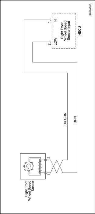
As the wheel is rotated, the speed sensor produces an AC voltage that increases with wheel speed. The HECU uses the frequency of the AC signal to calculate wheel speed. The speed sensor is connected to the HECU by a "twisted pair" of wires. Twisting reduces noise susceptibility that may cause a DTC to set.
Conditions for Setting the DTC
DTC C1203 can be set anytime the key is on and the HECU has detected an open, short to ground or a short to battery on the right front wheel speed circuit.
Action Taken When the DTC Sets
- The solenoid relay opens, removing power to the pump motor and solenoids.
- DTC C1203 is stored.
- ABS disabled, ABS Warning Lamp turns on.
Conditions for Clearing the DTC
- If the conditions that set DTC C1203 are no longer present, the DTC may be cleared by using the proper scan tool.
- The DTC that has not occurred in 100 drive cycles will be cleared from history data.
Diagnostic Aids
Thoroughly inspect the wiring and connectors when diagnosing intermittent DTC(s). This will include the following.
- Removal of the protective conduit and inspection for wiring for damage, shorts and contamination.
- Inspection for improperly formed and/or damaged terminals.
- Checking terminal contact (retention force) by using a spare male/female terminal.
- Removal of the terminals from the connectors to check for proper terminal to wire crimp.
If the drivers comments reflect that the ABS Warning Lamp is on only during moist environmental changes (rain, snow, vehicle wash), all wheel speed sensor circuitry should be thoroughly inspected for signs of water intrusion. If the DTC is not current, simulate the effects of water intrusion. Use the following procedure. Spray the suspected area with a 5 percent salt-water solution. Then test-drive the vehicle over various road surfaces such as (bumps, turns, etc) above 24 kph (15 mph). If the DTC sets then replace the suspected harness and or sensor.
When measuring wheel speed sensor resistance insure the vehicle is at room temperature, since resistance will increase with temperature.
Failure to perform the previous steps carefully and fully can result in misdiagnosis, unnecessary component replacement and reoccurrence of DTC C1203.
C1203 Right Front Wheel Speed Sensor Circuit Open or Shorted
| Step | Action | Value(s) | Yes | No |
| 1 | Was the diagnostic circuit check performed? | - | Go to Step 3 | Go to Step 2 |
| 2 | Perform the Diagnostic Circuit Check. Did you find problem? | - | Go to Step 3 | System OK |
| 3 | - Ignition switch "OFF".
- Inspect the right front wheel speed sensor, jumper harness and the toothed ring for physical damage.
Is any physical damage noted? | - | Go to Step 4 | Go to Step 5 |
| 4 | Repair the damage to the right front wheel speed sensor, jumper harness and/or toothed ring. | - | System OK | - |
| 5 | Test-drive vehicle at various speeds and over various road surfaces. Did C1203 reset? | - | Go to Step 7 | Go to Step 6 |
| 6 | DTC C1203 is intermittent. Refer to Diagnostic Aids. | - | System OK | - |
| 7 | - Ignition switch "OFF". vehicle in park.
- Raise and suitably support the vehicle.
- Disconnect the right front jumper harness from the Right Front Wheel Speed Sensor.
- Connect an ohmmeter to terminals 2 and 1 of the Right Front Wheel Speed Sensor.
Is the resistance with in specified range?. | 800-1600 Ohms (Resistance will vary with temperature) | Go to Step 9 | Go to Step 8 |
| 8 | Replace the right front wheel speed sensor. | - | System OK | - |
| 9 | - Right front jumper harness still disconnected from the speed sensor.
- Connect an ohmmeter to terminal 1 of the right front wheel speed sensor and then to body ground.
Is the resistance within the specified range? | OL(open circuit) | Go to Step 10 | Go to Step 8 |
| 10 | - Disconnect the HECU harness from the HECU.
- Disconnect the right front jumper harness from the ABS body harness.
- Connect an ohmmeter to HECU harness terminal 2 and then the ABS body harness terminal 1.
Is the resistance within the specified range? | Less than2 ohms | Go to Step 12 | Go to Step 11 |
| 11 | Repair the open or high resistance between terminals 2 and 1. | - | System OK | - |
| 12 | - HECU harness still disconnected from the HECU.
- Right front jumper harness still disconnected from the ABS body harness.
- Connect an ohmmeter to HECU harness terminal 1 and then to ABS body harness terminal 2.
Is the resistance within the specified range? | Less than2 ohms | Go to Step 4 | Go to Step 13 |
| 13 | Repair the open or high resistance between terminals 1 and 2. | - | System OK | - |
| 14 | - HECU harness still disconnected from the HECU.
- Right front jumper harness still disconnected from the ABS body harness.
- Connect a voltmeter to HECU harness terminal 2 and then to body ground.
Is the voltage within the specified range? | Less than 1volt | Go to Step 16 | Go to Step 15 |
| 15 | Repair the short to voltage between terminals 2 and 1. | - | System OK | - |
| 16 | - HECU harness still disconnected from the HECU.
- Right front jumper harness still disconnected from the ABS body harness.
- Connect a voltmeter to HECU harness terminal 1 and then to body ground.
Is the voltage within the specified range? | Less than 1volt | Go to Step 18 | Go to Step 17 |
| 17 | Repair the short to voltage between terminals 1 and 2. | - | System OK | - |
| 18 | - HECU harness still disconnected from the HECU.
- Right front jumper harness still disconnected from the ABS body harness.
- Connect an ohmmeter to HECU harness terminal 2 and then to body ground.
Is the resistance within the specified range? | OL(open circuit) | Go to Step 20 | Go to Step 19 |
| 19 | Repair the short to ground between terminals 2 and 1. | - | System OK | - |
| 20 | - HECU harness still disconnected from the HECU.
- Right front jumper harness still disconnected from the ABS body harness.
- Connect an ohmmeter to HECU harness terminal 1 and then to body ground. Left front jumper harness still disconnected from the ABS body harness. Connect an ohmmeter to HECU harness terminal 1 and then to body ground. Is the resistance within the specified range?
Is the resistance within the specified range? | OL(open circuit) | Go to Step 22 | Go to Step 21 |
| 21 | Repair the short to ground between terminals 1 and 2. | - | System OK | - |
| 22 | - HECU harness still disconnected from the HECU.
- Right front jumper harness still disconnected from the ABS body harness.
- Connect an ohmmeter to HECU harness terminal 1 and 2.
Is the resistance within the specified range? | OL(open circuit) | Go to Step 24 | Go to Step 23 |
| 23 | Repair the short between the 2 circuits. | - | System OK | - |
| 24 | - Replace the Right Front Wheel Speed Sensor Jumper Harness.
- Test-drive the vehicle at various speeds and various road surfaces.
Did C1203 reset? | - | Go to Step 25 | System OK |
| 25 | Replace the HECU. | - | System OK | - |
C1204 Right Front Wheel Speed Excessive Variation
Circuit Description
As the wheel is rotated, the speed sensor produces an AC voltage that increases with wheel speed. The HECU uses the frequency of the AC signal to calculate wheel speed. The speed sensor is connected to the HECU by a "twisted pair" of wires. Twisting reduces noise susceptibility that may cause a DTC to set.
Conditions for Setting the DTC
All of the following must be true for C1204 to set.
- C1200 or C1203 or C1206 or C1209 not current.
- Brake switch off.
- The right front wheel speed is accelerating or decelerating beyond reasonable limits.
Action Taken When the DTC Sets
- The solenoid relay opens, removing power from the pump motor and solenoids.
- DTC C1204 is stored.
- ABS disabled, ABS Warning Lamp turns on.
Conditions for Clearing the DTC
- If the conditions that set DTC C1204 are no longer present, the DTC may be cleared by using the proper scan tool.
- The DTC that has not occurred in 100 drive cycles will be cleared from history data.
Diagnostic Aids
Thoroughly inspect the wiring and connectors when diagnosing intermittent DTC(s). This will include the following.
- Removal of the protective conduit and inspection for wiring for damage, shorts and contamination.
- Inspection for improperly formed and/or damaged terminals.
- Checking terminal contact (retention force) by using a spare male/female terminal.
- Removal of the terminals from the connectors to check for proper terminal to wire crimp.
If the drivers comments reflect that the ABS Warning Lamp is on only during moist environmental changes (rain, snow, vehicle wash), all wheel speed sensor circuitry should be thoroughly inspected for signs of water intrusion. If the DTC is not current, simulate the effects of water intrusion. Use the following procedure. Spray the suspected area with a 5 percent salt-water solution. Then test-drive the vehicle over various road surfaces such as (bumps, turns, etc) above 24 kph (15 mph). If the DTC sets then replace the suspected harness and/or sensor.
A careful visual inspection of the toothed ring for damaged such as cracks and tooth damage should be performed. If the DTC sets at the same speed every drive cycle, the toothed ring is most likely damaged.
Failure to perform the previous steps carefully and fully can result in misdiagnosis, unnecessary component replacement and reoccurrence of DTC C1204.
C1204 Right Front Wheel Speed Excessive Variation
| Step | Action | Value(s) | Yes | No |
| 1 | Was the Diagnostic Circuit Check Completed? | - | Go to Step 3 | Go to Step 2 |
| 2 | Perform the Diagnostic Circuit Check prior to performing DTC C1204 trouble chart. Did you find problem? | - | Go to Step 3 | System OK |
| 3 | Was C1203 set as a current or history DTC? | - | Go to Step 4 | Go to Step 5 |
| 4 | Perform C1203 diagnostic chart prior to performing DTC C1204 trouble chart. | - | System OK | - |
| 5 | - Ignition switch "OFF".
- Ispect the right front wheel speed sensor and the jumper harness for damage.
- Perform a complete and thorough inspection of the right front toothed ring for damage. (cracks, missing teeth, looseness)
Is any physical damage noted? | - | Go to Step 6 | Go to Step 7 |
| 6 | Repair the damage to the right front wheel speed sensor, jumper harness and/or the toothed ring. | - | System OK | - |
| 7 | - Vehicle in park.
- Connect a Scan Tool and select data list.
- Monitor the wheel speed sensors.
- Start the vehicle, and monitor wheel speed sensors with engine running but vehicle not moving.
- Lightly depress the accelerator pedal to increase engine idle speed.
Did C1204 reset or did the right front wheel speed read above 0 mph when the vehicle was in park with the engine running. | - | Go to Step 8 | Go to Step 9 |
| 8 | The cause of C1204 is ignition noise coupled onto the Right Front Speed Sensor circuits. Inspect the routing of the right front ABS body harness and/or jumper harness for potential ignition noise sources such as spark plug wires. Reroute wiring as needed. | - | System OK | - |
| 9 | - Scan tool still connected.
- Monitor the wheel speed sensors.
- Test-drives the vehicle up to the maximum-posted speed limit, and slowly decelerates to zero. Do this several times.
Did C1204 reset or did the right front wheel speed vary more than 5 kph (3 mph) when compared to any one of the other wheels during the drive? | - | Go to Step 11 | Go to Step 10 |
| 10 | DTC C1204 is intermittent, refer to Diagnostic Aids. | - | System OK | - |
| 11 | - Vehicle in park, Ignition switch "OFF".
- Raise and suitably support the vehicle.
- Disconnect the right front jumper harness from the Right Front Wheel Speed sensor.
- Connect an ohmmeter to terminals 2 and 1 of the Right Front Wheel Speed sensor.
Is the resistance within the specified range? | 800-1600 Ohms (Resistance will vary with temperature) | Go to Step 13 | Go to Step 12 |
| 12 | Replace the right front wheel speed sensor. | - | System OK | - |
| 13 | - Speed sensor still disconnected from the jumper harness.
- Connect a voltmeter to terminals 2 and 1 of the right front speed sensor.
- Select the AC milli-volt scale.
- Spin the right front wheel while observing the voltage on the meter.
Is the AC voltage within the specified range? | At least 100mV | Go to Step 14 | Go to Step 12 |
| 14 | - Disconnect the HECU harness from the HECU.
- Disconnect the right front jumper harness from the ABS body harness.
- Connect an ohmmeter to HECU harness terminal 2 and then to ABS body harness terminal 1.
Is the resistance within the specified range? | Less than2 ohms | Go to Step 16 | Go to Step 15 |
| 15 | Repair the source open or high resistance between terminals 2 and 1. | - | System OK | - |
| 16 | - HECU harness still disconnected from the HECU.
- Jumper harness still disconnected from the body harness.
- Connect an ohmmeter to HECU harness terminal 1 and then to ABS body harness terminal 2.
Is the resistance within the specified range? | Less than2 ohms | Go to Step 18 | Go to Step 17 |
| 17 | Repair the open or high resistance between terminals 1 and 2. | - | System OK | - |
| 18 | - HECU harness still disconnected from the HECU.
- Jumper harness still disconnected from the body harness.
- Connect an ohmmeter between HECU harness terminals 1 and 2.
Is the resistance within the specified range? | OL(open circuit) | Go to Step 20 | Go to Step 19 |
| 19 | Repair the short between the 2 wires. | - | System OK | - |
| 20 | - Replace the right front jumper harness.
- Test-drive the vehicle at various speeds and road surfaces.
Did C1204 reset? | - | Go to Step 20 | System OK |
| 21 | Replace the HECU. | - | System OK | - |
C1205 Right Front Wheel Speed Sensor No Signal
Circuit Description
As the wheel is rotated, the speed sensor produces an AC voltage that increases with wheel speed. The HECU uses the frequency of the AC signal to calculate wheel speed. The speed sensor is connected to the HECU by a"twisted pair" of wires. Twisting reduces noise susceptibility that may cause a DTC to set.
Conditions for Setting the DTC
All of the following must be true for C1205 to set.
- C1200 or C1203 or C1206 or C1209 not current.
- ABS not active.
- Brake switch off.
- The right front wheel speed equals 0, and all of the remaining Wheel Speed Sensors are greater than 8 km/hr (5 mph) for at least 2.5 seconds.
Action Taken When the DTC Sets
- The solenoid relay opens, removing power from the pump motor and solenoids.
- DTC C1205 is stored.
- ABS disabled, ABS Warning Lamp turns on.
Conditions for Clearing the DTC
- If the conditions that set DTC C1205 are no longer present, the DTC may be cleared by using the proper scan tool.
- The DTC that has not occurred in 100 drive cycles will be cleared from history data.
Diagnostic Aids
Thoroughly inspect the wiring and connectors when diagnosing intermittent DTC(s). This will include the following.
- Removal of the protective conduit and inspection of wiring for damage, shorts and contamination.
- Inspection for improperly formed and/or damaged terminals.
- Checking terminal contact (retention force) by using a spare male/female terminal.
- Removal of the terminals from the connectors to check for proper terminal to wire crimp.
If the drivers comments reflect that the ABS Warning Lamp is on only during moist environmental changes (rain, snow, vehicle wash), all wheel speed sensor circuitry should be thoroughly inspected for signs of water intrusion. If the DTC is not current, simulate the effects of water intrusion. Use the following procedure. Spray the suspected area with a 5 percent salt-water solution. Then test-drive the vehicle over various road surfaces such as (bumps, turns, etc) above 24 kph (15 mph). If the DTC sets then replace the suspected harness and/or sensor.
When measuring wheel speed sensor resistance insures the vehicle is at room temperature, since resistance will increase with temperature.
Failure to perform the previous steps carefully and fully can result in misdiagnosis, unnecessary component replacement and reoccurrence of DTC C1205.
C1205 Right Front Wheel Speed Sensor No Signal
| Step | Action | Value(s) | Yes | No |
| 1 | Was the Diagnostic Circuit Check Completed? | - | Go to Step 3 | Go to Step 2 |
| 2 | Perform the Diagnostic Circuit Check prior to performing this trouble tree. Did you find problem? | - | Go to Step 3 | System OK |
| 3 | - Ignition switch "OFF".
- Inspect the righ front wheel speed sensor, jumper harness and toothed ring for physical damage.
Is any physical damage noted? | - | Go to Step 4 | Go to Step 5 |
| 4 | Repair the damage to the right front wheel speed sensor, jumper harness and/or toothed ring. Check the airgap. | 0.2~0.8mm | System OK | - |
| 5 | Was DTC C1203 set as a current or history code? | - | Go to Step 6 | Go to Step 7 |
| 6 | Perform diagnostics for DTC C1203 prior to performing this table. | - | System OK | - |
| 7 | - Connect a Scan Tool and select data list.
- Monitor the wheel speed sensors.
- Test-drives vehicle above 24 kph (15 mph) and slowly decelerates to zero, do this several times.
Did C1205 reset or did the right front wheel speed suddenly drop to zero prior to the vehicle coming to a complete stop? | - | Go to Step 9 | Go to Step 8 |
| 8 | DTC C1205 is intermittent. Refer to diagnostic aids. | - | System OK | - |
| 9 | - Ignition switch "OFF".
- Raise and suitably support the vehicle.
- Disconnect the HECU harness from the HECU.
- Connect a voltmeter to HECU harness terminals 1 and 2.
- Select the AC mill volt scale.
- Spin the right front wheel while observing the voltmeter. (voltage should increase as wheel speed increases)
Is the AC voltage within the specified range? | At least 100mV | Go to Step 10 | Go to Step 11 |
| 10 | Replace the HECU. | - | System OK | - |
| 11 | - Disconnect the right front jumper harness from the Right Front Wheel Speed Sensor.
- Connect an ohmmeter to terminals 2 and 1 of the Right Front Wheel Speed Sensor.
Is the resistance within the specified range? | 800-1600 Ohms (Resistance will vary with temperature) | Go to Step 13 | Go to Step 12 |
| 12 | Replace the right front wheel speed sensor. | - | System OK | - |
| 13 | - Right front jumper harness still disconnected from the right front speed sensor.
- Connect a voltmeter to terminals 2 and 1 of the left front wheel speed sensor.
- Select the AC mill volt scale.
- Spin the right front wheel while observing the voltmeter. (voltage should increase as wheel speed increases)
Is the AC voltage within the specified range? | At least 100mV | Go to Step 14 | Go to Step 12 |
| 14 | - Disconnect the right front jumper harness from the ABS body harness.
- HECU harness still disconnected from the HECU.
- Connect an ohmmeter to HECU harness terminals 9 and 10.
Is the Resistance within the specified range? | OL(open circuit) | Go to Step 16 | Go to Step 15 |
| 15 | Find and repair the short between the 2 circuits. | - | System OK | - |
| 16 | - HECU harness still disconnected from the HECU.
- Right front jumper harness still disconnected from the ABS body harness.
- Connect an ohmmeter to HECU harness terminal 12 and then to ABS body harness terminal 1.
Is the resistance within the specified range? | Less than2 ohms | Go to Step 18 | Go to Step 17 |
| 17 | Repair the open or high resistance between terminals 2 and 1. | - | System OK | - |
| 18 | - HECU harness still disconnected from the HECU.
- Right front jumper harness still disconnected from the ABS body harness.
- Connect an ohmmeter to HECU harness terminal 1 and then to ABS body harness terminal 2.
Is the resistance within the specified range? | Less than2 ohms | Go to Step 20 | Go to Step 19 |
| 19 | Repair the open or high resistance between terminal 1 and 2. | - | System OK | - |
| 20 | - Replace the right front wheel speed jumper harness
- Test-drive the vehicle at various speeds and road surfacess.
Did C1205 reset? | - | Go to Step 10 | System OK |
C1206 Left Rear Wheel Speed Sensor Circuit Open or Shorted
Circuit Description
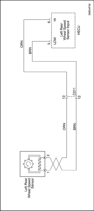
As the wheel is rotated, the speed sensor produces an AC voltage that increases with wheel speed. The HECU uses the frequency of the AC signal to calculate wheel speed. The speed sensor is connected to the HECU by a "twisted pair" of wires. Twisting reduces noise susceptibility that may cause a DTC to set.
Conditions for Setting the DTC
DTC C1206 can be set anytime the key is on and the HECU has detected an open, short to ground or a short to battery on the left rear wheel speed circuit.
Action Taken When the DTC Sets
- The solenoid relay opens, removing power to the pump motor and solenoids.
- DTC C1206 is stored.
- ABS disabled, ABS Warning Lamp turns on.
Conditions for Clearing the DTC
- If the conditions that set DTC C1206 are no longer present, the DTC may be cleared by using the proper scan tool.
- The DTC that has not occurred in 100 drive cycles will be cleared from history data.
Diagnostic Aids
Thoroughly inspect the wiring and connectors when diagnosing intermittent DTC(s). This will include the following.
- Removal of the protective conduit and inspection for wiring for damage, shorts and contamination.
- Inspection for improperly formed and/or damaged terminals.
- Checking terminal contact (retention force) by using a spare male/female terminal.
- Removal of the terminals from the connectors to check for proper terminal to wire crimp.
If the drivers comments reflect that the ABS Warning Lamp is on only during moist environmental changes (rain, snow, vehicle wash), all wheel speed sensor circuitry should be thoroughly inspected for signs of water intrusion. If the DTC is not current, simulate the effects of water intrusion. Use the following procedure. Spray the suspected area with a 5 percent salt-water solution. Then test-drive the vehicle over various road surfaces such as (bumps, turns, etc) above 24 kph (15 mph). If the DTC sets then replace the suspected harness and or sensor.
When measuring wheel speed sensor resistance insure the vehicle is at room temperature, since resistance will increase with temperature.
Failure to perform the previous steps carefully and fully can result in misdiagnosis, unnecessary component replacement and reoccurrence of DTC 1206.
C1206 Left Rear Wheel Speed Sensor Circuit Open or Shorted
| Step | Action | Value(s) | Yes | No |
| 1 | Was the diagnostic circuit check performed? | - | Go to Step 3 | Go to Step 2 |
| 2 | Perform the Diagnostic Circuit Check. Did you find problem? | - | Go to Step 3 | System OK |
| 3 | - Ignition switch "OFF".
- Inspect the left rear wheel speed sensor, jumper harness and the toothed ring for physical damage.
Is any physical damage noted? | - | Go to Step 4 | Go to Step 5 |
| 4 | Repair the damage to the left rear wheel speed sensor, jumper harness and/or toothed ring. | - | System OK | - |
| 5 | Test-drive vehicle at various speeds and over various road surfaces. Did C1206 reset? | - | Go to Step 7 | Go to Step 6 |
| 6 | DTC C1206 is intermittent. Refer to Diagnostic Aids. | - | System OK | - |
| 7 | - Ignition switch "OFF". vehicle in park.
- Raise and suitably support the vehicle.
- Disconnect the left rear jumper harness from the left rear Wheel Speed Sensor.
- Connect an ohmmeter to terminals 2 and 1 of the left rear Wheel Speed Sensor.
Is the resistance with in specified range?. | 800-1600 Ohms (Resistance will vary with temperature) | Go to Step 9 | Go to Step 8 |
| 8 | Replace the left rear wheel speed sensor. | - | System OK | - |
| 9 | - Left rear jumper harness still disconnected from the speed sensor.
- Connect an ohmmeter to terminal 1 of the left rear wheel speed sensor and then to body ground.
Is the resistance within the specified range? | OL(open circuit) | Go to Step 10 | Go to Step 8 |
| 10 | - Disconnect the HECU harness from the HECU.
- Disconnect the left rear jumper harness from the ABS body harness.
- Connect an ohmmeter to HECU harness terminal 5 and then the ABS body harness terminal 1.
Is the resistance within the specified range? | Less than2 ohms | Go to Step 12 | Go to Step 11 |
| 11 | Repair the open or high resistance between terminals 5 and 1. | - | System OK | - |
| 12 | - HECU harness still disconnected from the HECU.
- Left rear jumper harness still disconnected from the ABS body harness.
- Connect an ohmmeter to HECU harness terminal 6 and then to ABS body harness terminal 2.
Is the resistance within the specified range? | Less than2 ohms | Go to Step 4 | Go to Step 13 |
| 13 | Repair the open or high resistance between terminals 6 and 2. | - | System OK | - |
| 14 | - HECU harness still disconnected from the HECU.
- Left rear jumper harness still disconnected from the ABS body harness.
- Connect a voltmeter to HECU harness terminal 5 and then to body ground.
Is the voltage within the specified range? | Less than 1volt | Go to Step 16 | Go to Step 15 |
| 15 | Repair the short to voltage between terminals 5 and 1. | - | System OK | - |
| 16 | - HECU harness still disconnected from the HECU.
- Left rear jumper harness still disconnected from the ABS body harness.
- Connect a voltmeter to HECU harness terminal 6 and then to body ground.
Is the voltage within the specified range? | Less than 1volt | Go to Step 18 | Go to Step 17 |
| 17 | Repair the short to voltage between terminals 6 and 2. | - | System OK | - |
| 18 | - HECU harness still disconnected from the HECU.
- Left rear jumper harness still disconnected from the ABS body harness.
- Connect an ohmmeter to HECU harness terminal 5 and then to body ground.
Is the resistance within the specified range? | OL(open circuit) | Go to Step 20 | Go to Step 19 |
| 19 | Repair the short to ground between terminals 5 and 1. | - | System OK | - |
| 20 | - HECU harness still disconnected from the HECU.
- Left rear jumper harness still disconnected from the ABS body harness.
- Connect an ohmmeter to HECU harness terminal 5 and then to body ground. Left rear jumper harness still disconnected from the ABS body harness.
- Connect an ohmmeter to HECU harness terminal 6 and then to body ground. Is the resistance within the specified range?
Is the resistance within the specified range? | OL(open circuit) | Go to Step 22 | Go to Step 21 |
| 21 | Repair the short to ground between terminal 6 and 2. | - | System OK | - |
| 22 | - HECU harness still disconnected from the HECU.
- Left rear jumper harness still disconnected from the ABS body harness.
- Connect an ohmmeter to HECU harness terminal 5 and 6.
Is the resistance within the specified range? | OL(open circuit) | Go to Step 24 | Go to Step 23 |
| 23 | Repair the short between the 2 circuits. | - | System OK | - |
| 24 | - Replace the Left Rear Wheel Speed Sensor Jumper Harness.
- Test-drive the vehicle at various speeds and various road surfaces.
Did C1206 reset? | - | Go to Step 25 | System OK |
| 25 | Replace the HECU. | - | System OK | - |
 | |  | |
| © Copyright Chevrolet Europe. All rights reserved |