SECTION 4E
REAR DRUM BRAKES
SPECIFICATIONS
General Specifcations
Application | Millimeters | Inches |
Brake Drums: | . | . |
Inside Diameter | 200.00 | 7.87 |
Maximum Revore Diameter | 201.00 | 7.91 |
Out-to-Round | 0.04 | 0.001 |
Wheel Cylinder Diameter: | . | . |
Rear | 20.64 | 0.81 |
Fastener Tightening Specifications
Application | N•m | Lb-Ft | Lb-In |
Brake Line | 16 | 12 | - |
Brake Wheel Hub/Backing Plate-to-Rear Axle Nuts | 28 | 21 | - |
Rear Hub Caulking Nut | 190 | 140 | - |
Wheel Cylinder-to-Backing Plate Bolt | 8 | - | 71 |
DIAGNOSIS
Lining Inspection
- Raise and suitably support the vehicle.
- Remove the wheel. Refer to Section 2E, Tires andWheels.
- Release the parking brake.
- Remove the drum. Refer to " Drum"in this section.
- Measure the lining thickness. The minimum liningthickness is 0.5 mm (0.02 inch).
Caution : To avoid injury when servicing brakeparts, do not create dust by grinding or sanding thebrake linings or by cleaning the wheel brake partswith a dry brush or with compressed air.
Important : Replace the shoe and lining assembly inaxle sets only.
- Install the drum, if removed.
- Install the wheel, if removed. Refer to Section 2E, Tires andWheels.
- Lower the vehicle.
Drums
Whenever brake drums are removed, they should bethoroughly cleaned and inspected to see if the drumsare cracked, scored, deeply grooved, or beyond thespecified out-of-round limit.
- A cracked drum is unsafe for further service andmustbe replaced. Do not attempt to weld a cracked drum.Smooth out any slight scores.
- Heavy or extensive scoring will cause excessivebrake lining wear and may require refinishing thedrum braking surface.
- If the brake linings are slightly worn but are still reusableand the drum is grooved, polish the drum with afine emery cloth but do not refinish it. Eliminating allgrooves in the drum and smoothing the ridges on thelining would remove too much metal and lining. If leftalone, the grooves and ridges match, and satisfactoryservice can be obtained. If the brake linings need tobe replaced, refinish a grooved drum. A grooveddrum, used with a new lining, will not only wear thelining, but also will make it difficult, if not impossible,to obtain proper brake performance.
- An out-of-round drum makes accurate brake shoeadjustment impossible and is likely to cause excessivewear of other parts of the brake mechanism. Anout-of-round drum can also cause severe and irregulartire tread wear, as well as a pulsating brake pedal.
- The extent to which a drum is worn or out of roundcan be measured accurately with an inside micrometerfitted with the proper extension rods. When measuringa drum for wear or the extent to which it is outof round, take measurements from the inside edge tothe outside edge of the machined surface at 90-degreeintervals around the circumference of the drum.When the drum exceeds the specified out-of-roundlimit, refinish the drum.
MAINTENANCE AND REPAIR
ON-VEHICLE SERVICE


Brake Adjustment
Removal Procedure
- Release the parking brake.
- Operate the brake at least 10 times until the jumpingof the adjustment spring on the adjustment nut can nolonger be heard on either brake drum.
- Raise and suitably support the vehicle.
- Remove the rear wheels. Refer to Section 2E, Tires andWheels. Mark the position of the wheels relativeto the wheel hubs.
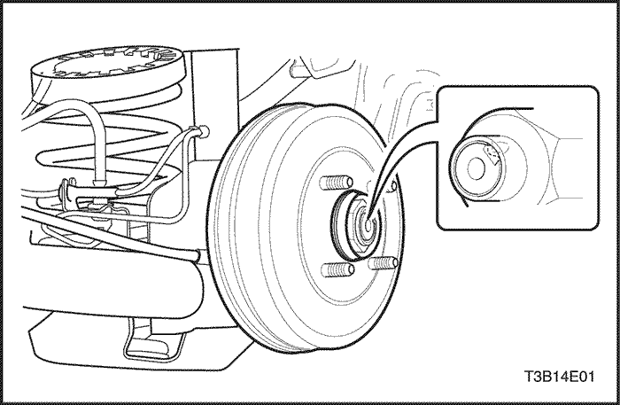
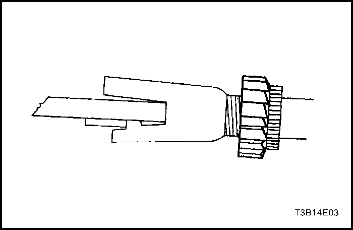
- Remove the caulking nut.
- Remove the brake drum.
- Using the rear brake adjuster nut, turn the adjusterassembly in until there is a sufficient amount of dragon the brake drum.
- Make sure that the parking brake lever stops areagainst the edge of the shoe web. If they are not,loosen the parking brake cable at the equalizer. Referto Section 4G, Parking Brake.
Installation Procedure
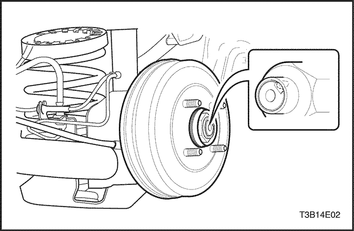
- Positionthe rear brake drum. Fasten the rear hubcaulking nut.
Tighten
Tighten the one-piece rear hub caulking nut to 190 N•m(140 lb-ft).
- Install the rear wheels. Refer to Section 2E, Tires andWheels. Mark the position of the wheels relativeto the wheel hubs.
Important : The brake pedal must be operated morethan 10 times. When the clicking can no longer beheard, the clearance between the brake shoe and drumis adjusted.
- Apply the foot brake several times until the clicking ofthe adjustment actuator can no longer be heard.
- Adjust the parking brake. Refer to Section 4G, Parking Brake.
Shoe and Lining
Removal Procedure
- Raise and suitably support the vehicle.
- Remove the rear wheels. Refer to Section 2E, Tires andWheels. Mark the position of the wheels relativeto the wheel hubs.
- Mark the position of the wheels relative to the wheelhub.
- Loosen the parking brake cable. Refer to Section 4G, Parking Brake. Mark the position of the wheels relativeto the wheel hubs.
- Remove the drum caulkimg nut and the brake drum.
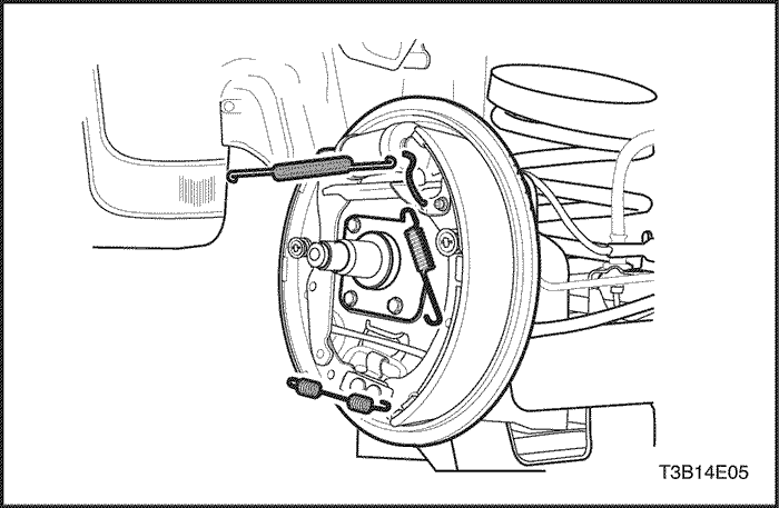
- Loosen the leading shoe hold-down return spring.(The ABS braking system configuration is illustrated.)
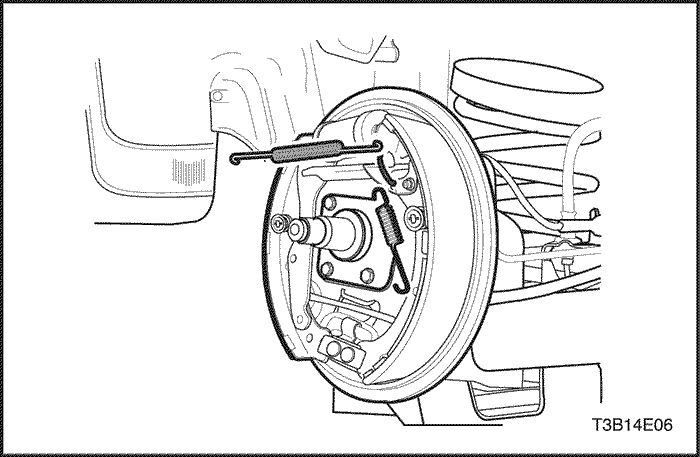
- Disconnect the upper link of the connecting link springof the leading shoe to relieve tension on theupper return spring.
- Remove the upper return spring and the adjuster.
- Unfasten the trailing shoe and lining assembly holddownreturn spring.
- Disconnect the trailing shoe and lining assembly onthe right side.
- Detach the lower return spring.
Installation Procedure
- Measure the minimum brake lining thickness. Referto "Lining Inspection"in this section.
- Clean the adjuster assembly and apply grease.
Notice : If any parts are of questionable strength or qualitybecause of heat discoloration, excessive stress, orwear, the shoes, the springs, or the adjuster assemblyshould be replaced.
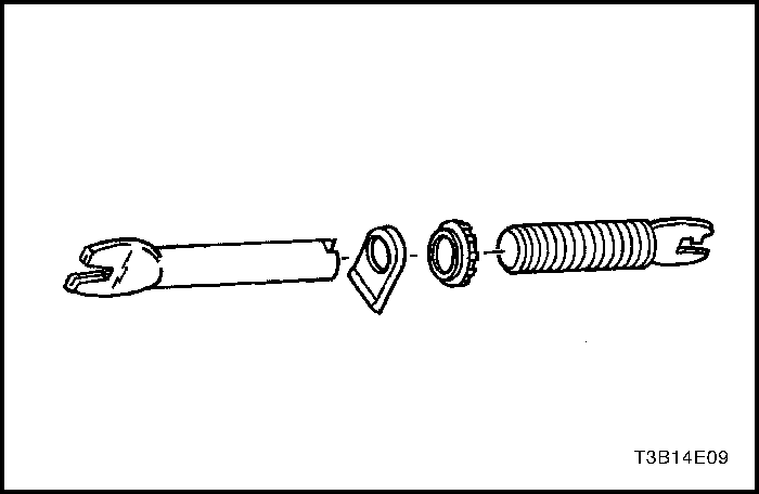
- Inspect the threads of the adjuster assembly forsmooth rotation.
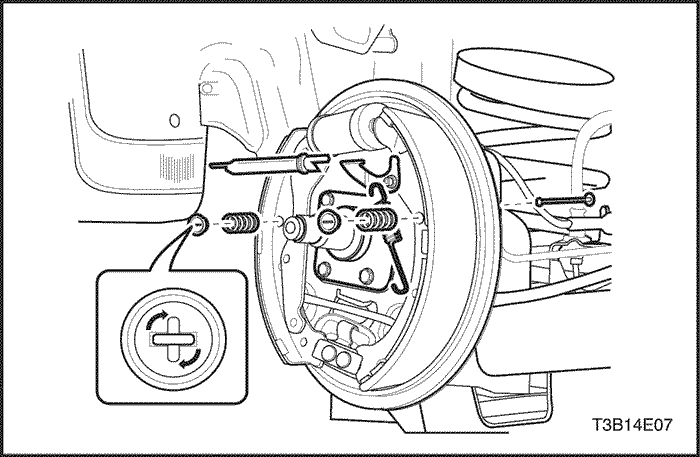
- Install the trailing shoe and lining assembly with thehold-down spring, the washer, and the pin.
- Make sure the parking brake cable is properlyrouted and attached to the shoe lever.
Notice : Do not overstretch the lower return spring.
- Fasten the lower return spring on the shoe.
- Position the leading shoe and the adjuster assemblyagainst the backing plate.
- Fasten the lower return spring to the leading shoe.
- Install the adjuster assembly.
- Turn the adjuster in as far as possible.
- Position the spring clip toward the backing plate.
- Install the leading shoe with the hold-down spring.
- Attach the leading shoe upper link-spring connection,which applies tension to the upper returnspring.
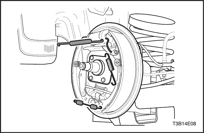
Notice : Do not overstretch the upper return spring.
- Install the upper return spring from the spring connectinglink to the brake shoe.
Notice : The nut must not lock firmly at the end of theadjustment assembly.
- Before installing the brake drum, make sure the adjusterassembly nut is drawn all the way to the stop.
- Install thebrake drum and fasten it with the rear hub caulking nut .
Tighten
Tighten the rear hub caulking nut to 190 N•m(140 lb-ft).
- Install the rear wheels. Refer to Section 2E, Tires and Wheels.
- Adjust the rear wheel brakes. Refer to "Brake Adjustment"in this section.
- Adjust the parking brake. Refer to Section 4G, ParkingBrake.
- Lower the vehicle.
Wheel Cylinder Assembly
Removal Procedure
- Raise and suitably support the vehicle.
- Remove the rear wheels. Refer to Section 2E, Tires and Wheels.
- Mark the position of the wheels relative to the wheelhubs.
- Remove the brake drum.
- Remove the shoe and lining. Refer to "Shoe and Lining"in this section.
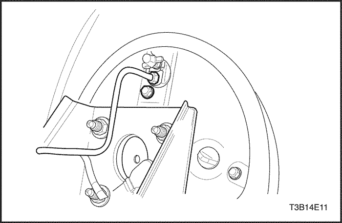
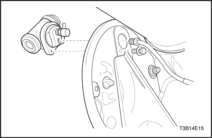
- Clean dirt and foreign material from around the wheelcylinder brake line inlet, the pilot, and the bolt.
- Disconnect the brake line from the wheel cylinder.
- Plug the opening in the brake line to prevent fluid lossor contamination.
- Remove the wheel cylinder-to-backing plate bolt.
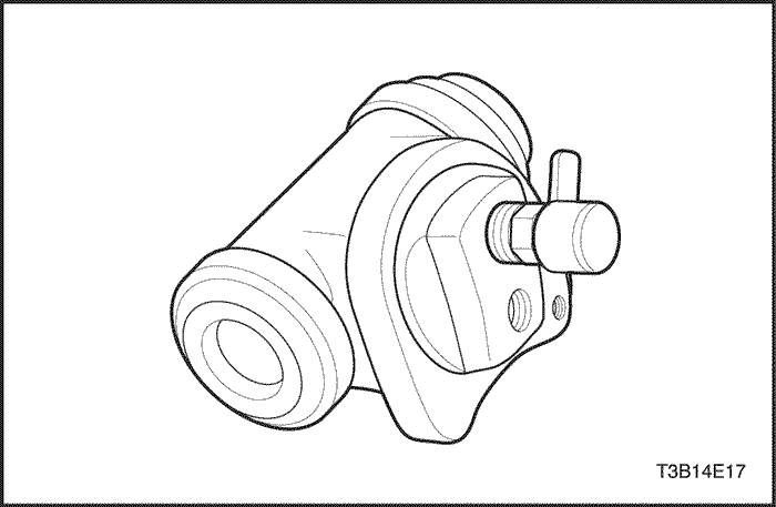
- Gently tap out the wheel cylinder from the backingplate, using care not to damage the bleeder valve orits cap.
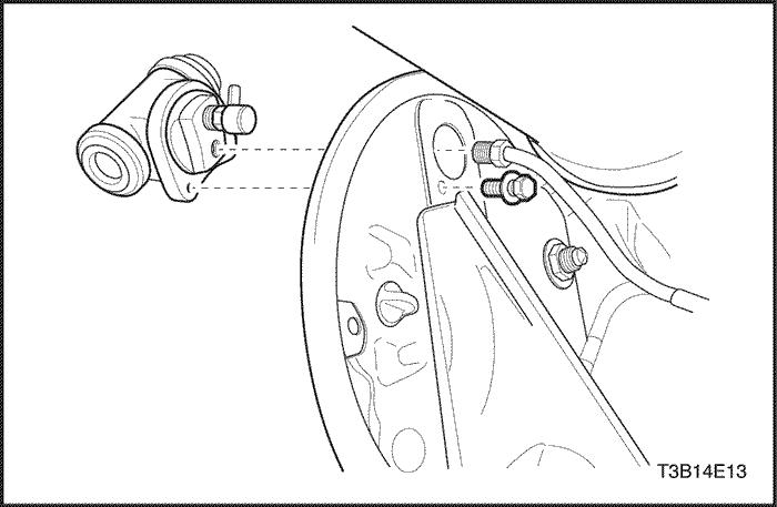
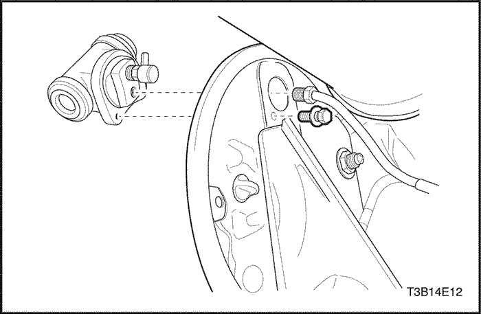
Installation Procedure
- Install the wheel cylinder to the backing plate with thewheel cylinder bolt.
Tighten
Tighten the wheel cylinder-to-backing plate bolt to8 N•m (71 lb-in).
- Connect the brake line to the wheel cylinder.
Tighten
Tighten the brake line to 16 N•m (12 lb-ft)
- Install the shoe and lining, and the brake drum. Referto "Shoe and Lining"in this section.
- Bleed the brakes. Refer to Section 4A, HydraulicBrakes.
Backing Plate
Removal Procedure
- Raise and suitably support the vehicle.
- Remove the brake shoe components, including completeremoval of the parking brake with the retainer.Refer to "Shoe and Lining"in this section and Section 4A, Hydraulic Brakes.
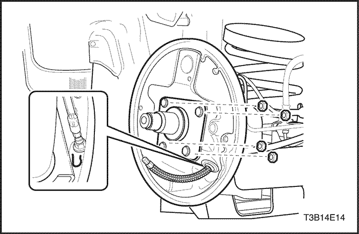
- Remove the nuts that secure the wheel hub assemblyto the backing plate.
- Remove the brake line and plug the opening in theline to prevent fluid loss or contamination.
- Remove the wheel cylinder assembly. Refer to "Wheel Cylinder Assembly"in this section.
- Remove the wheel hub assembly.
- In case of ABS brake, disconnect the cable that goes to the wheel speed sensor.
- Separate the backing plate and the gasket.
Installation Procedure
- Place the backing plate with a new gasket on thewheel hub. (The ABS hub is shown.).
- Insert the complete wheel hub/backing plate assemblyinto the rear axle plate. In case of ABS Brakes, Install the nuts and connectthe wheel speed sensor.
Tighten
Tighten the brake wheel hub/backing plate-to-rearaxle nuts to 28 N•m (21 lb-ft).
- Install the brake wheel cylinder assembly to the backingplate. Refer to "Wheel Cylinder Assembly"in this section.
- Connect the brake line.
Tighten
Tighten the brake line to 16 N•m (12 lb-ft).
- Install the brake components. Refer to "Shoe and Lining"in this section.
- Install the parking brake cable with the retainer by attachingthe cable to the brake shoe lever. Refer to Section 4G, ParkingBrake.
- Bleed the brakes. Refer to Section 4A, HydraulicBrakes.
- Lower the vehicle.
UNIT REPAIR
Wheel Cylinder
Disassembly Procedure
- Remove the wheel cylinder assembly from the backingplate. Refer to "Wheel Cylinder Assembly"in this section.
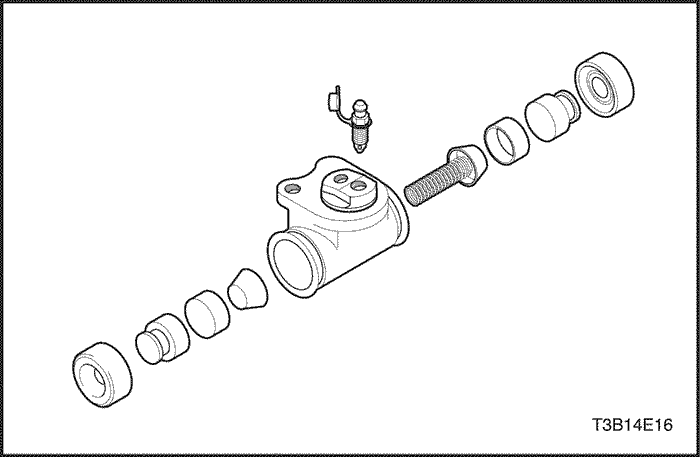
- Twist off the boots, the pistons, and the seals fromeach end of the wheel cylinder.
- Remove the spring assembly.
- Remove the bleeder cap and the bleeder valve.
Assembly Procedure
- Inspect the wheel cylinder bore and the pistons forscoring, nicks, corrosion, and wear.
- Use a crocus cloth to polish out light corrosion in thewheel cylinder bore.
Important : If the bore will not clean up with a crocuscloth, replace the assembly.
- Clean all the parts in clean denatured alcohol or brakefluid. Dry all the parts with unlubricated compressedair and lubricate the new seals, the pistons, and thewheel cylinder bore with clean brake fluid before assembly.
- Thinly coat all the parts except the dust caps withbrake cylinder fluid.
- Fasten the bleeder valve and the cap to the wheel cylinder.
- Attach to the wheel cylinder the spring assembly, followedby the pistons, the seals, and the boots.
- Inspect the pistons for free movement.
- Install the wheel cylinder assembly. Refer to "Wheel Cylinder Assembly"in this section.
GENERAL DESCRIPTIONAND SYSTEM OPERATION
Drum Brakes
This drum brake assembly is a leading/trailing shoe design.Both brake shoes are held against the wheel cylinderpistons by the lower return spring and the fixedanchor plate near the lower return spring. When thebrakes are applied, the wheel cylinder pistons moveboth shoes out to contact the drum. With forward wheelrotation, the forward brake shoe will wrap into the drumand become self-energized. With reverse wheel rotation,the rear brake shoe is self-energized. Force fromthe brake shoes is transferred to the anchor platethrough the backing plate to the axle flange. Adjustmentis automatic and occurs on any service brake application.Do not switch the position of shoes that have beenin service, as this may render the self-adjustment featureinoperative and result in increased pedal travel.
Notice : To avoid damaging the vehicle, observe the followingdirections:
- Replace all the components included in the repair kitsused to service this drum brake.
- Do not use lubricated shop air on the brake parts, asdamage to the rubber components may result.
- If any hydraulic component is removed or disconnected,it may be necessary to bleed all or part of thebraking system.
- Replace the shoe and linings in axle sets only.
- The torque values specified are for dry, unlubricatedfasteners.
- Perform service operations on a clean bench that isfree from all mineral oil materials.


