SECTION 4G
PARKING BRAKE
SPECIFICATIONS
Fastener Tightening Specifications
Application | N•m | Lb-Ft | Lb-In |
Front Muffler Heat Shield Nuts | 2.5 | - | 22 |
Parking Brake Cable-to-Rear Axle Bracket Bolt | 12 | - | 106 |
Parking Brake Cable-to-Underbody Side and Near SideBracket Nuts | 12 | - | 106 |
Parking Brake Console Hood-to-Tunnel Bracket Screws | 2.5 | - | 22 |
Parking Brake Lever-to-Vehicle Underbody Bolts | 20 | 15 | - |
Parking Brake Switch-to-Parking Brake Lever Screw | 4 | - | 35 |
Rear Hub Caulking Nut | 190 | 140 | - |
MAINTENANCE AND REPAIR
ON-VEHICLE SERVICE


Parking Brake Adjustment
Adjustment Procedure
- Adjust the rear brakes. Refer to Section 4E, RearDrum Brakes.
- Release the parking brake.
- Raise and suitably support the vehicle.
- Check the parking brake cables for free movement.
- Lower the vehicle
- Move the front seats backward to ensure the enough working space.
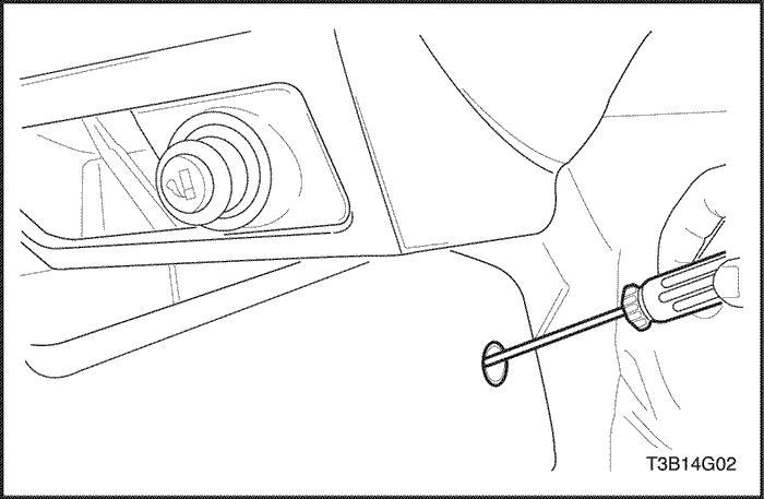
- Pry off the plastic caps that cover the access holes tothe parking brake console hood-to-tunnel bracketscrews.
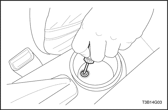
- Unfasten the screws that secure the parking brakeconsole hood to the tunnel brackets.
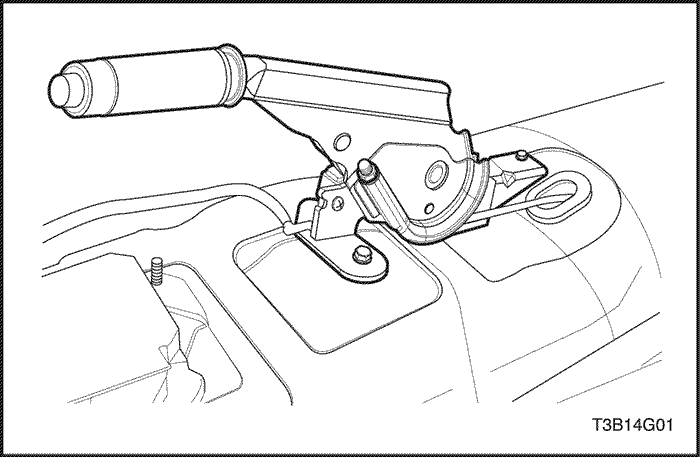
- Raise the console hood to expose the parking brakelever assembly and the adjustment nut.
- Partially raise and suitably support the vehicle.
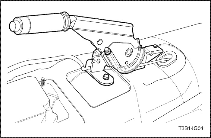
- Turn the adjustment nut on the lever assembly untilthe wheels are difficult to turn.
- Loosen the nut until the rear wheels are just free toturn.
- Lower the vehicle.
- Position the parking brake console hood and fastenit to the tunnel brackets with the screws.
Tighten
Tighten the parking brake console hood-to-tunnelbracket screws to 2.5 N•m (22 lb-in).
- Snap in the plastic caps that cover the access holesto the parking brake console hood-to-tunnel bracketscrews.
- Adjust the front seats to their previous position.
Parking Brake Lever
Removal Procedure
- Release the parking brake.
- Move the front seats forward.
- Pry off the plastic caps that cover the access holes tothe parking brake console hood-to-tunnel bracketscrews.
- Remove the screws that secure the parking brakeconsole hood-to-the-tunnel brackets. Raise the consolehood.
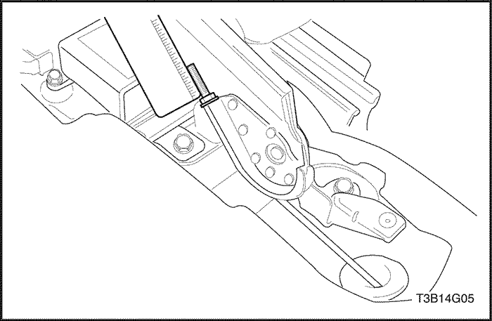
- Measure the thread length from the end of the pushrodto the adjustment nut before removing the adjustment nut.
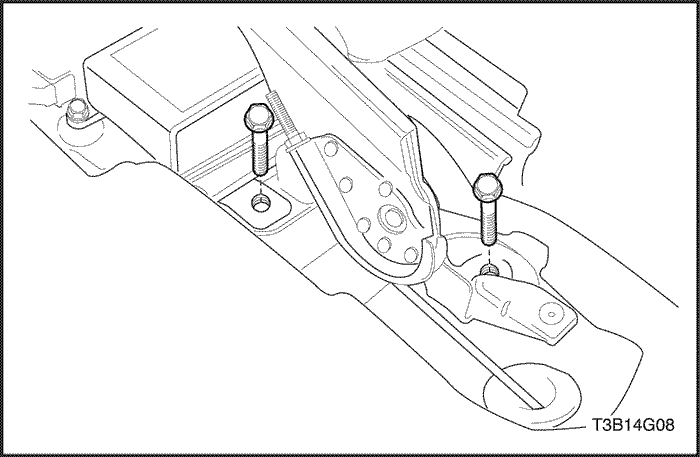
- Remove the complete parking brake lever assemblyand the cable from the assembly by unfastening theparking brake lever-to-vehicle underbody bolts andremoving the adjustment nut.
- Disconnect the parking brake warning lamp switch connector.
Notice : The parking brake switch should be replaced ifthe BRAKE warning light in the instrument panel clusterdoes not glow when the parking brake is applied with theignition switch ON.
- If necessary, remove the parking brake switch,which is attached to the parking brake lever assemblyby a small screw.
- Inspect the parking brake lever cable and the levergrip for damage, and replace if necessary.
Installation Procedure
Notice : If the parking brake lever is bent or damaged orif a new grip is required, replace the complete parkingbrake lever assembly, which includes a new parkingbrake switch and lever cable.
- Fasten the parking brake switch to the parking brakelever with the screw.
Tighten
Tighten the parking brake switch-to-parking brake leverscrew to 4 N•m (35 lb-in).
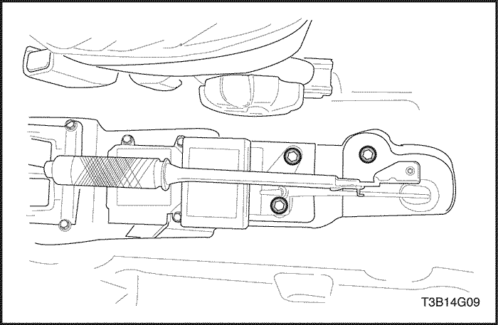
- Fasten the parking brake lever assembly to the vehicleunderbody. Insert the cable, to the pushrod.
- Tighten the hex adjusting nut on the pushrod approximatingthe measurement noted in the removal procedure.
Tighten
Tighten the parking brake lever-to-vehicle underbodybolts to 20 N•m (15 lb-ft).
- Connect the parking brake warning lamp switch connector.
- Install the screws that secure the parking brake console hood to the tunnel brackets.
Tighten
Tighten the parking brake console hood-to-tunnelbracket screws to 2.5 N•m (22 lb-in).
- Install the plastic caps that cover the access holes tothe parking brake console hood-to-tunnel bracketscrews.
Parking Brake Cable
Removal Procedure
- Release the parking brake lever.
- Remove the rear wheels. Refer to Section 2E, Tiresand Wheels.
- Remove the retaining ring for the parking brake cableon each side of the vehicle.
- Remove the plastic sleeve.
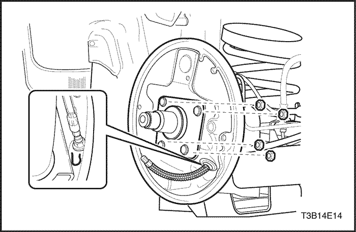
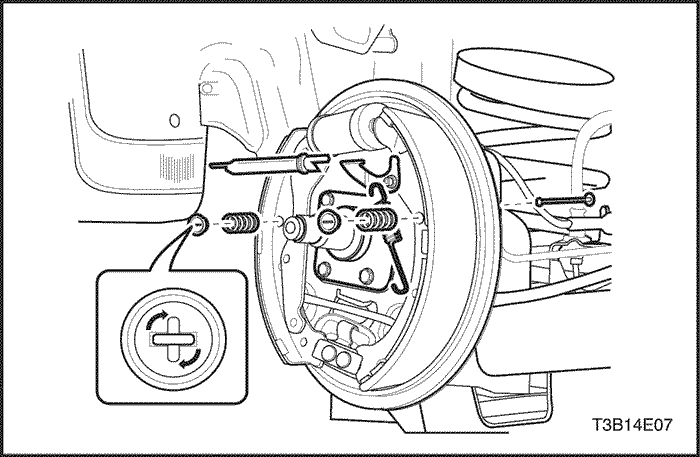
- Remove the brake cable from the parking brake shoelever and from the brake backing plate.
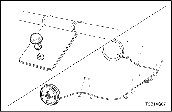
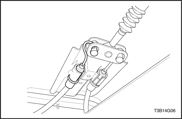
- Remove the bolts that fastens the brake cable tothe holding bracket on the rear axle. Remove the boltsfrom the rear alxe mounting bracket on each side of the vehicle.
- Remove the bolt that fastens the brake cable to theunderbody side bracket on each side of the vehicle.Remove the cable.
- Remove the parking brake cables from the weldedbody bracket.
Installation Procedure
- Install the new parking brake cable through the brakebacking plate. Use a new cable if the original is frayedor damaged. Attach the cable to the parking brakeshoe lever.
- Insert the plastic sleeve into the brake backing plateand press in the retaining ring. Make sure the parkingbrake cable is routed correctly.
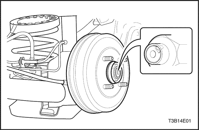
- Install the brake drums and fasten the rear hub caulking nut.
Tighten
Tighten the rear hub caulking nut to 190 N•m (140 lb-ft).
- Install the rear wheels. Refer to Section 2E, Tires andWheels.
- Install the parking brake cable to the underbody sidebrackets on each side of the vehicle, and a bracketnear the underbody side bracket.
Tighten
Tighten the parking brake cable-to-underbody sideand near side bracket bolts to 12 N•m (106 lb-in).
- Install the parking brake cable on the rear axlebrackets on each side of the vehicle.
Tighten
Tighten the parking brake cable-to-rear axle bracketbolt to 12 N•m (106 lb-in).
- Insert the parking brake cables through the weldedbody bracket.
- Adjust the length of parking brake cable. Refer to "Parking Brake Adjustment" in this section.
GENERAL DESCRIPTIONAND SYSTEM OPERATION
Parking Brake
This braking system uses a BRAKE warning light locatedin the instrument panel cluster. When the ignitionswitch is in the START position, the BRAKE warninglight should glow and go off when the ignition switch returnsto the RUN position. Whenever the parking brakeis applied and the ignition switch is ON, the BRAKEwarning light should glow.
When the brake is firmly applied, the parking brakeshould securely hold the vehicle with ample pedal travelremaining. Check for frayed cables, rust, etc., or anycondition that may inhibit present (or future) free movementof the parking brake lever assembly.


