GENERAL DESCRIPTIONAND SYSTEM OPERATION
General System Description
The purpose of the MGH-25 Antilock Brake System (ABS) is to minimize wheel slip during heavy braking. MGH-25 performs this function by monitoring the speed of each wheel and controlling the brake fluid pressure to each wheel independently during a braking event. This allows the driver to retain directional stability and better steering capability.
Basic Knowledge Required
Before using this section, it is important that you have a basic knowledge of the following items. Without this basic knowledge, it will be difficult to use the diagnostic procedures contained in this section.
- Basic Electrical Circuits : You should understand the basic theory of electricity and know the meaning of potential (voltage), current (amperes) and resistance (ohms). You should understand what happens in a circuit with open or shorted wire. You should be able to read and understand a wiring diagram.
- Use of Circuit Test Tools : You should be familiar with a Digital Multimeter (DMM), and be familiar with the meter controls and how to use them correctly. You should be able to measure voltage, resistance and current. You should know how to use jumper wire to bypass components for testing circuits.
ABS System Components
The MGH-25 Antilock Brake System (ABS) consists of a conventional hydraulic brake system plus antilock components. The conventional brake system includes a vacuum booster, master cylinder, front disc brakes, rear drum brakes, interconnecting hydraulic brake pipes and hoses, brake fluid level sensor and the brake warning lamp indicator.
The ABS components include a hydraulic unit, an HECU (Hydraulic Electronic Control Unit), system fuse, four wheel speed sensor (one at each wheel), interconnecting wiring, ABS indicator, the DDRP (De-coupled Dynamic Rear Proportioning) indicator (which is connected to the parking lamp) and the rear drum brakes. See "ABS Component Locator" in this section for the general layout of this system.
The hydraulic unit with the attached EBCM (Electronic Brake Control Module) is located between the surge tank and the fire wall on the left side of the vehicle.
The basic hydraulic unit configuration consists of hydraulic check valves, two solenoid valves for each wheel, a hydraulic pump, two accumulators. The hydraulic unit controls hydraulic pressure to the front calipers and the rear wheel cylinders by modulating hydraulic pressure to prevent wheel lockup.
Base Braking Mode
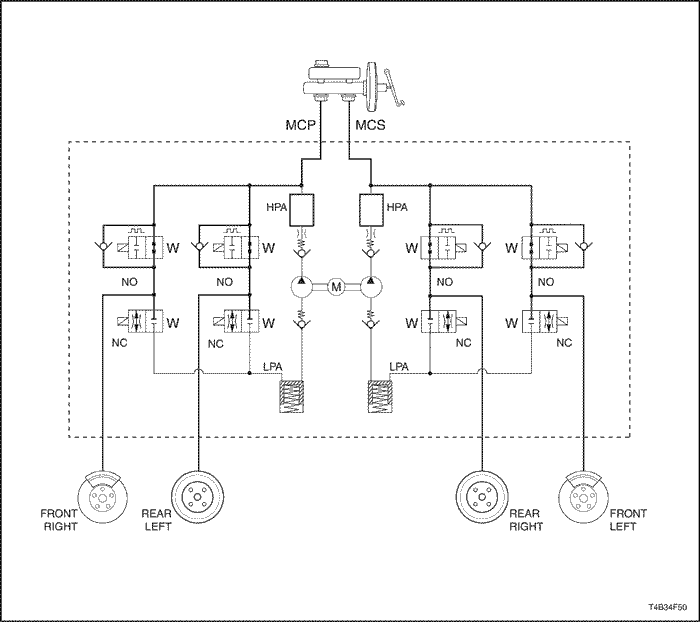
The baseline braking mode of MGH-25 Antilock Braking System (ABS) system used in this vehicle is a diagonal split system. In this system, one master cylinder circuit supplies pressure to the right front and the left rear brakes; the other circuit supplies pressure to the left front and the right rear brakes. All valves in the hydraulic modulator are in their normal, non-energized positions as shown in the drawings found in "ABS System Components" in this section.
MCP : Master Cylinder Primary
MCS : Master Cylinder Secondary
NO : Normal Open Solenoid Valve
NC : Normal Close Solenoid Valve
M : Electric Motor
LPA : Low Pressure Accumulator
HPA : High Pressure Accumulator
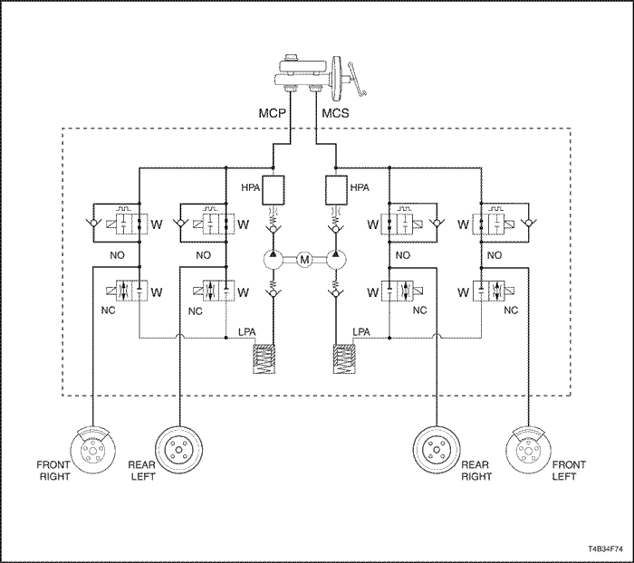
Antilock Braking Mode - Apply
If during the pressure hold or pressure decrease mode the ECU (Electronic Control Unit) senses that wheel slip has reduced, the ECU will increase the pressure to the affected wheel(s) by applying master cylinder pressure. The NO valve is opened and the NC valve is closed, now base brake master cylinder pressure can be applied to the wheel.
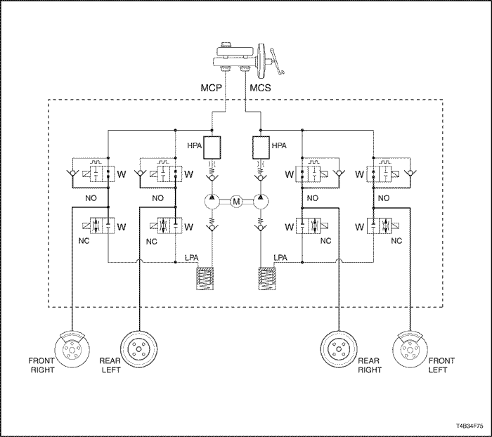
Antilock Braking Mode - Hold
When the ECU (Electronic Control Unit) senses the wheel slip, the ECU closes the NO valve and keeps the NC valve closed in the brake pressure modulator valve in order to isolate the system. This holds the pressure steady on the brake so that the hydraulic pressure does not increase or decrease.
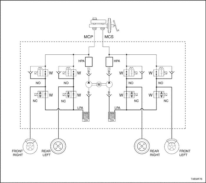
Antilock Braking Mode - Release
If during the pressure hold mode the ECU (Electronic Control Unit) still senses wheel slip, the HECU will decrease the pressure to the affected wheel(s). The NO valve is left closed and the NC valve is opened. The excess fluid/pressure is temporary stored into an accumulator within the brake pressure modulator valve, until the pump can return the fluid to the master cylinder reservoir.
DDRP (De-Coupled Dynamic Rear Proportioning)
DDRP (De-coupled Dynamic Rear Proportioning) is proportioning system to maintain vehicle stability during braking. In normal braking condition, equal wheel speed should be maintained for efficient and balanced braking. In hard braking condition, a vehicle requires relatively less brake force at rear wheel due to vehicle's weight transfer to the front. DDRP maintains desired brake pressure to the rear wheel by using the ABS rear inlet and outlet valve in order to provide efficient braking and vehicle stability. In DDRP system, Power to the Rear Hold Valve Solenoid is provided from Ignition. If the following fault conditions are existing, the Red Brake Warning Lamp will be illuminated.
- Two Wheel Speed Sensors inoperative on same axle.
- Rear inlet solenoid inoperative.
- Battery 2 (Motor Input) short to ground.
- Battery 1 (HECU Input) open or short to the ground.
- Motor ground open or short to battery.
- HECU ground open or short to battery.
- Ignition open or short to ground.
DDRP (De-Coupled Dynamic Rear Proportining) Failure Modes
. | . | De-coupled DRP |
Part | Hypothesized Failure | ABS Warning Lamp | Brake Warning Lamp | D-DRP Status |
Sensor RF | Short or Open | ON | - | Degraded |
Sensor LF | Short or Open | ON | - | Degraded |
Sensor RR | Short or Open | ON | - | Degraded |
Sensor LR | Short or Open | ON | - | Degraded |
Two Sensors, Same Axle | Short or Open | ON | ON | Disabled |
One Front & One Rear Sensor | Short or Open | ON | - | Degraded |
Motor | Short to Ground - LOW Side | ON | - | Degraded |
Short to Ground - HI Side | ON | - | Degraded |
Short to Battery - LOW Side | ON | - | Degraded |
Short to Battery - HI Side | - | - | None |
Motor Circuit Open | ON | - | Degraded |
Motor Stalled | ON | - | Degraded |
Front Apply Solenoids | Short or Open | ON | - | Degraded |
Front Release Solenoids | Short or Open | ON | - | Degraded |
Rear Apply Solenoids | Short or Open | ON | - | Degraded |
Rear Release Solenoids | Short or Open | ON | ON | Degraded |
System Relay | Open (Unable to turn on) | ON | - | Degraded |
Shorted On (Unable to turn off) | - | - | None |
Battery 2 (Motor) | Short to GND | ON | ON | Degraded |
Open | - | - | Low Voltage |
Ground (Motor) | Open or Short To Batt | ON | - | Enabled |
Battery 1 (ECU, Solenoids) | Open or Short To GND | ON | ON | Disabled |
Ground (ECU, Solenoids) | Open or Short To Batt | ON | ON | Disabled |
Ignition | Open or Short To GND | ON | ON | Disabled |
Brake Switch | Not Applicable | - | - | Enabled |
Serial Communication | Open or Short | ON | ON | Enabled |
HECU (Hydraulic Electronic Control Unit)
The HECU performs the following primary functions;
order to provide efficient braking and vehicle stability. In DDRP system, Power to the Rear Hold Valve Solenoid is provided from Ignition. If the following fault conditions are existing, The Red Brake Warning Lamp will be illuminated.
- Monitor wheel speed sensor inputs.
- Detect wheel slip tendencies.
- Control the brake system while in the antilock control mode.
- Monitor the system for proper electrical operation.
The HECU continuously checks the speed of each wheel to determine if any wheel is beginning to slip. If any wheel slip tendency is detected, the HECU commands appropriate valve positions to modulate brake fluid pressure in some or all of the hydraulic circuits to prevent wheel slip and provide optimum braking. The HECU continues to control pressure in individual hydraulic circuits until a slipping tendency is no longer present. Also the HECU continuously monitors the ABS for proper operation. If the HECU detects an error, it can disable the ABS function and turn on the ABS Warning Lamp in the instrument cluster. The HECU also controls the display of the ABS DTCs (Diagnostic Trouble Codes) while in diagnostic mode.
Solenoid Relay
The solenoid relay, provides power to the pump motor and solenoids. The switch in the relay is normally open, but is commanded to close during initialization. The relay switch will remain closed for the remainder of the drive cycle as long as no DTCs (Diagnostic Trouble Codes) set which required the switch to open. If a DTC sets which requires the relay to be commanded off, battery voltage will be removed from the pump motor and solenoids for the remainder of the current drive cycle and ABS cannot function. The relay is an integral part of the HECU and cannot be serviced separately.
Wheel Speed Sensors and Rings
A wheel speed sensor is present at each wheel. The sensors transmit wheel speed information to the HECU by means of a small AC voltage. This voltage is generated by magnetic induction caused by passing a thoothed sensor ring past a stationary sensor. The magnitude and frequency of the AC voltage are proportional to the speed of the wheel and both will increase with increasing speed. The signal is transmitted to the HECU through interface that can cause false or noisy wheel speed sensor input to the HECU. Two different types of wheel speed sensors are used for MGH-25 system.
ABS Warning Lamp (AMBER)
The ABS warning lamp is located in the instrument cluster and will illuminate if a malfunction in the ABS is detected by the HECU. The ABS warning lamp informs the driver that a condition exists which results in turning off the antilock brake function. If only the ABS is warning lamp is on, normal braking with full power assist is available.
Conditions for the ABS warning lamp to turn on are as follows.
- ABS malfunction detected. As previously described, the ABS warning lamp turns on when a problem has been found in the ABS.
- Instrument panel cluster bulb check. When the ignition is turned to ON, the ABS warning lamp will turn on for approximately three seconds and then turn off.
Brake Warning Lamp (RED)
The red brake warning lamp in the in the instrument cluster and will illuminate to warn the driver of condition in the brake system, which may result in reduced braking ability. The lamp will illuminate when the parking brake is applied or not fully released, or if the brake fluid level switch is closed (when the brake fluid is low in the master cylinder reservoir). When the brake fluid level switch is closed (low condition) a brake warning lamp will stay illuminated until the condition has been repaired. Also some failure modes in MGH-25 system will illuminate the lamp to let the drivers know DDRP (De-coupled Dynamic Rear Proportioning) is disabled
| © Copyright Chevrolet Europe. All rights reserved |