Diagnostic Trouble Code (DTC) P0502
Vehicle Speed Sensor (VSS) Circuit Low Voltage
Circuit Description
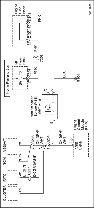
Vehicle speed information is provided to the Engine Control Module (ECM) by the Vehicle Speed Sensor (VSS). The VSS is a permanent magnet generator that is mounted in the transaxle and produces a pulsing voltage whenever vehicle speed is over 3 mph (5 km/h). The Alternating Current (AC) voltage level and the number of pulses increases with vehicle speed. The ECM converts the pulsing voltage into mph (km/h) and then supplies the necessary signal to the instrument panel for speedometer/ odometer operation and to the cruise control module and multi-function alarm module operation. This Diagnostic Trouble Code (DTC) will detect if vehicle speed is reasonable according to engine rpm and load.
Conditions for Setting the DTC
- Vehicle speed is less than 5 km/h (3.1 mph) for Power and Decel test.
- Engine is running.
- Engine Coolant Temperature (ECT) is greater than 60 °C (140 °F).
- Ignition voltage is between 11-16 volts.
- Power Test
- The rpm is between 1200 and 4000.
- Throttle Position (TP) sensor is between 25% and 60%.
- Engine load is greater than 60 kPa (8.7 psi).
- Deceleration Test
- Generator compensated Manifold Absolute Pressure (MAP) is less than 30 kPa (4.4 psi)
- Change in rpm per cycle is less than 50 rpm/cycle.
- Throttle Position (TP) sensor is less than or equal to 0.8%.
- The rpm is between 1800 and 6000.
- DTC(s) P0106, P0107, P0108, P0117, P0118, P0122, P0123, P0201, P0202, P0203, P0204, P0300, P0351, P0352, P0402, P0404, P0405, and P0406 are not set.
Action Taken When the DTC Sets
- The Malfunction Indicator Lamp (MIL) will illuminate after three consecutive trip with a fail.
- The ECM will record operating conditions at the time the diagnostic fails. This information will be stored in the Freeze Frame and Failure Records buffers.
- A history DTC is stored.
Conditions for Clearing the MIL/DTC
- The MIL will turn off after four consecutive ignition cycles in which the diagnostic runs without a fault.
- A history DTC will clear after 40 consecutive warm-up cycles without a fault.
- DTC(s) can be cleared by using the scan tool.
- Disconnecting the ECM battery feed for more than 10 seconds.
Diagnostic Aids
An intermittent problem may be caused by a poor connection, rubbed-through wire insulation, or a wire that is broken inside the insulation.
VSS signal circuit should be thoroughly checked for the following conditions:
- Backed-out terminals
- Improper mating
- Broken locks
- Improperly formed
- Damaged terminals
- Poor terminal-to-wire connection
- Physical damage to the wiring harness
Ensure the VSS is correctly tightened with proper torque to the transmission housing.
Refer to "Intermittents"in this section.
Test Description
Number(s) below refer to the step number(s) on the Diagnostic Table.
- The On-Board Diagnostic (EOBD) System Check prompts the technician to complete some basic checks and store the freeze frame and failure records data on the scan tool if applicable. This creates an electronic copy of the data taken when the malfunction occurred. The information is then stored on the scan tool for later reference.
- The permanent magnet generator only produces a signal if the drive wheels are turning greater than 5 mph (8 km/h). This step determines if DTC P0502 is the result of a hard failure or an intermittent condition.
- Proper engine loads cannot be achieved in a shop environment to properly run the vehicle within the Freeze Frame Data conditions. It will be necessary to drive the vehicle on the road to obtain the proper engine loads.
- This step verifies that the ECM is receiving a signal from the vehicle speed sensor.
- Refer to service bulletin information for the latest calibration update.
- Refer to the latest Techline information for programming procedures.
- A resistance reading that is higher than the specified value indicates that the VSS circuitry is open.
- If the displayed resistance is less than the 1300 ohms, the VSS high and low circuits are shorted together.
- This checks the resistance of the VSS if no opens or shorts were found on the VSS high and low circuits.
- The replacement ECM must be reprogrammed. Refer to the latest Techline procedure for ECM reprogramming.
DTC P0502 - Vehicle Speed Sensor (VSS) Circuit Low Voltage
| Step | Action | Value(s) | Yes | No |
| 1 | Perform an On-Board Diagnostic (EOBD) System Check. Was the check performed? | - | Go to Step 2 | |
| 2 | Notice : Running the vehicle in gear with the wheels hanging down at full travel will damage the drive axles. - Install a scan tool to the Data Link Connector (DLC).
- Raise the drive wheels.
- Support the lower control arms so that the drive axles are in a horizontal (straight) position.
- Start the engine and allow to idle in gear.
Does the scan tool display vehicle speed above the specific value? | 0 mph | Go to Step 3 | Go to Step 4 |
| 3 | - Turn the ignition ON.
- Review the Freeze Frame data and note the parameters.
- Operate the vehicle within the Freeze Frame conditions and Conditions for Setting this DTC.
Does the scan tool display vehicle speed above the specific value? | 0 mph | Go to Step 12 | Go to Step 4 |
| 4 | - Turn the ignition OFF.
- Disconnect the Vehicle Speed Sensor (VSS) connector.
- Turn the ignition ON.
- Using a voltmeter connected to ground, measure the voltage in VSS signal circuit, at terminal B.
Is the voltage near the specified value? | 10.1 v | Go to Step 5 | Go to Step 7 |
| 5 | Using a voltmeter connected to ground, measure the voltage at terminal C of the VSS connector. Is the voltage near the specified value? | 11-14 V | Go to Step 6 | Go to Step 8 |
| 6 | Using a ohmmeter connected to ground, measure the voltage at terminal A of the VSS connector. Is the voltage near the specified value? | 400 Ω | Go to Step 10 | Go to Step 9 |
| 7 | Check the VSS signal circuit for an open or short to ground and repair as needed. Is the repair complete? | - | Go to Step 12 | Go to Step 11 |
| 8 | Check the ignition circuit for an open and repair as needed. Is the repair complete? | - | Go to Step 12 | - |
| 9 | Check the VSS ground circuit for an open and repair as needed. Is the repair complete? | - | Go to Step 12 | - |
| 10 | - Turn the ignition OFF.
- Replace the VSS.
Is the repair complete? | - | Go to Step 12 | - |
| 11 | - Turn the ignition OFF.
- Replace the ECM.
Is the repair complete? | - | Go to Step 12 | - |
| 12 | - Using the scan tool, clear the Diagnostic Trouble Codes (DTCs).
- Start the engine and idle at normal operating temperature.
- Operate the vehicle within the conditions for setting this DTC as specified in the supporting text.
Does the scan tool indicate that this diagnostic has run and passed? | - | Go to Step 13 | Go to Step 2 |
| 13 | Check if any additional DTCs are set. Are any DTCs displayed that have not been diagnosed? | - | Go to Applicable DTC table | System OK |
Diagnostic Trouble Code (DTC) P0506
Idle Speed Low
Circuit Description
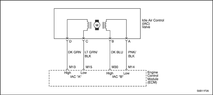
The Engine Control Module (ECM) controls the air entering into the engine with an Idle Air Control (IAC) Valve. To increase the idle rpm, the ECM commands the pintle inside the IAC valve away from the throttle body seat. This allows more air to bypass through the throttle blade. To decrease the rpm the ECM commands the pintle towards the throttle body seat. This reduces the amount of air bypassing the throttle blade. A scan tool will read the IAC valve pintle position in counts. The higher the counts, the more air that is allowed to bypass the throttle blade. This Diagnostic Trouble Code (DTC) determines if a low idle condition exists as defined as 100 rpm below the desired idle rpm.
Conditions for Setting the DTC
- No intrusive tests are active.
- DTC(s) P0106, P0107, P0108, P0112, P0113, P0117, P0118, P0122, P0123, P0131, P0132, P0133, P0135,P0141, P1133, P1134, P0171, P0172, P0201, P0202, P0203, P0204, P0300, P0336, P0351, P0352, P0402, P0404, P0405, P0406, P0443, and P0502 are not set.
- Engine is running more than 60 seconds.
- Barometric Pressure (BARO) is greater than 72 kPa (10.4 psi).
- Engine Coolant Temperature (ECT) is greater than 60°C.
- Ignition voltage is between 11 and 16 volts.
- Manifold Absolute Pressure is less than 60 kPa (8.7 psi).
- IAC valve is controlled fully opened.
- All of the above must be met for greater than 5 seconds.
Action Taken When the DTC Sets
- The Malfunction Indicator Lamp (MIL) will illuminate after three consecutive ignition cycle with a fail.
- The ECM will record operating conditions at the time the diagnostic fails. This information will be stored in the Freeze Frame and Failure Records buffers.
- A history DTC is stored.
Conditions for Clearing the MIL/DTC
- The MIL will turn off after four consecutive ignition cycles in which the diagnostic runs without a fault.
- A history DTC will clear after 40 consecutive warm-up cycles without a fault.
- DTC(s) can be cleared by using the scan tool.
- Disconnecting the ECM battery feed for more than 10 seconds.
Diagnostic Aids
Inspect the IAC valve electrical connection for proper mating.
Inspect the wiring harness for damage.
Inspect the throttle stop screw for signs of tampering.
Inspect the throttle linkage for signs of binding or excessive wear.
A slow or unstable idle may be caused by one of the following conditions:
- Fuel system too rich or too lean.
- Foreign material in the throttle body bore or in the air induction system.
- A leaking or restricted intake manifold.
- Excessive engine overloading. Check for seized pulleys, pumps, or motors on the accessory drive.
- Overweight engine oil.
Test Description
Number(s) below refer to the step number(s) on the Diagnostic Table.
- The On-Board Diagnostic (EOBD) System Check prompts the technician to complete some basic checks and store the freeze frame and failure records data on the scan tool if applicable. This creates an electronic copy of the data taken when the malfunction occurred. The information is then stored on the scan tool for later reference.
- A normally operating IAC system will be able to be extended and retracted by a scan tool and change the engine idle rpm. Valve movement is verified by an engine rpm change.
- If the scan tool was able to command the IAC valve smoothly, a malfunction may still exist internally within the IAC valve. This can be checked by checking the IAC valves internal resistance.
- The IAC circuits always have ground or voltage signals on them in pairs. If the test light illuminates on more or less than 2 terminals, 1 of the circuits is shorted to voltage or open.
- The IAC circuits always have ground or voltage signals on them in pairs. If the test light illuminates on more or less than 2 terminals, 1 of the circuits is shorted to ground or open
- The IAC circuits are constantly switched between ground and voltage so the test light should blink on all circuits when connected to ground.
- Any circuitry, that is suspected as causing the intermittent complaint, should be thoroughly checked for backed-out terminals, improper mating, broke locks, improperly formed or damaged terminals, poor terminal- to-wiring connections or physical damage to the wiring harness.
- A test light that remains ON constantly indicates that the circuit is shorted to voltage.
- The replacement ECM must be reprogrammed. Refer to the latest Techline procedure for ECM reprogramming.
- If no malfunctions have been found at this point and no additional DTCs were set, refer to "Diagnostic Aids" in this section for additional checks and information.
DTC P0506 - Idle Speed Low
| Step | Action | Value(s) | Yes | No |
| 1 | Perform an On-Board Diagnostic (EOBD) System Check. Was the check performed? | - | Go to Step 2 | |
| 2 | - Install a scan tool to the Data Link Connector (DLC).
- Operate the engine to idle speed.
- Transmission in park or neutral and the parking brake set.
- A/C is off.
- Using scan tool, command the Idle Air Control (IAC) valve up and down between the specified value.
Does the rpm change smoothly when he commanded by the scan tool? | 900-1200 rpm | Go to Step 3 | Go to Step 5 |
| 3 | - Turn the ignition OFF.
- Disconnect the IAC valve connector.
- Measure the resistance between terminal D and C of the IAC valve.
- Measure the resistance between terminal B and A of the IAC valve.
Is the resistance within the specified value? | 40-80 Ω | Go to Step 4 | Go to Step 13 |
| 4 | - Measure the resistance between terminal C and B of the IAC valve.
- Measure the resistance between terminal D and A of the IAC valve.
Is the resistance equal to the specified value? | ∞ | Go to Step 15 | Go to Step 13 |
| 5 | - Turn the ignition OFF.
- Disconnect the IAC valve connector.
- Turn the ignition ON.
- With test light connected to ground, probe the IAC connector terminals.
Does the test light illuminate on 2 terminals? | - | Go to Step 6 | Go to Step 7 |
| 6 | With test light connected to B+, probe the IAC connector terminals. Does the test light illuminate on 2 terminals? | - | Go to Step 8 | Go to Step 9 |
| 7 | Check for an open or short to ground in the IAC high and low circuits and repair as needed. Is the repair complete? | - | Go to Step 15 | Go to Step 10 |
| 8 | - Idle the engine.
- Connect a test light to ground, probe the IAC connector terminals.
Does the test light flash On and OFF for all terminals? | - | Go to Step 11 | Go to Step 12 |
| 9 | Check for an open or a short to voltage in the IAC valve high and low circuits and repair as needed. Is the repair complete? | - | Go to Step 15 | Go to Step 10 |
| 10 | Check the Engine control Module (ECM) connector for poor connections and repair as needed. Is the repair necessary? | - | Go to Step 15 | Go to Step 14 |
| 11 | Inspect the IAC valve passages and repair as needed. Is the problem found? | - | Go to Step 15 | Go to Step 13 |
| 12 | Check the test light. Does the test light remain on constantly for the terminals that did not blink? | - | Go to Step 9 | Go to Step 7 |
| 13 | - Turn the ignition OFF.
- Replace the IAC valve.
Is the repair complete? | - | Go to Step 15 | - |
| 14 | - Turn the ignition OFF.
- Replace the ECM.
Is the repair complete? | - | Go to Step 15 | - |
| 15 | - Using the scan tool, clear the Diagnostic Trouble Codes (DTCs).
- Start the engine and idle at normal operating temperature.
- Operate the vehicle within the Conditions for setting this DTC as specified in the supporting text.
Does the scan tool indicate that this diagnostic has run and passed? | - | Go to Step 16 | Go to Step 2 |
| 16 | Check if any additional DTCs are set. Are any DTCs displayed that have not been diagnosed? | - | Go to Applicable DTC table | System OK |
Diagnostic Trouble Code (DTC) P0507
Idle Speed High
Circuit Description
The Engine Control Module (ECM) controls the air entering into the engine with an Idle Air Control (IAC) Valve. To increase the idle rpm, the ECM commands the pintle inside the IAC valve away from the throttle body seat. This allows more air to bypass through the throttle blade. To decrease the rpm the ECM commands the pintle towards the throttle body seat. This reduces the amount of air bypassing the throttle blade. A scan tool will read the IAC valve pintle position in counts. The higher the counts, the more air that is allowed to bypass the throttle blade. This Diagnostic Trouble Code (DTC) determines if a high idle condition exists as defined as 200 rpm above the desired idle rpm.
Conditions for Setting the DTC
- No intrusive tests are active.
- DTC(s) P0106, P0107, P0108, P0112, P0113, P0117, P0118, P0122, P0123, P0131, P0132, P0133, P0135, P0141, P1133, P1134, P0171, P0172, P0201, P0202, P0203, P0204, P0300, P0336, P0351, P0352, P0402, P0404, P0405, P0406, P0441, P0443, and P0502 are not set.
- Engine is running more than 60 seconds.
- Barometric Pressure (BARO) is greater than 72 kPa (10.4 psi).
- Engine Coolant Temperature (ECT) is greater than 60°C.
- Ignition voltage is between 11 and 16 volts.
- The Intake Air Temperature (IAT) is greater than -20 °C (-4 °F).
- IAC valve is controlled fully closed.
- All of the above must be met for greater than 5 seconds.
- Idle engine speed error is greater than 200 rpm for 10 seconds.
Action Taken When the DTC Sets
- The Malfunction Indicator Lamp (MIL) will illuminate after three consecutive ignition cycle with a fail.
- The ECM will record operating conditions at the time the diagnostic fails. This information will be stored in the Freeze Frame and Failure Records buffers.
- A history DTC is stored.
Conditions for Clearing the MIL/DTC
- The MIL will turn off after four consecutive ignition cycles in which the diagnostic runs without a fault.
- A history DTC will clear after 40 consecutive warm-up cycles without a fault.
- DTC(s) can be cleared by using the scan tool.
- Disconnecting the ECM battery feed for more than 10 seconds.
Diagnostic Aids
Inspect the IAC valve electrical connection for proper mating.
Inspect the wiring harness for damage.
Inspect the throttle stop screw for signs of tampering.
Inspect the throttle linkage for signs of binding or excessive wear.
Inspect the positive crankcase ventilation (PCV) valve and PCV hose.
A slow or unstable idle may be caused by one of the following conditions:
- Fuel system too rich or too lean.
- Foreign material in the throttle body bore or in the air induction system.
- A leaking or restricted intake manifold.
- Excessive engine overloading. Check for seized pulleys, pumps, or motors on the accessory drive.
- Overweight engine oil.
Test Description
Number(s) below refer to the step number(s) on the Diagnostic Table.
- The On-Board Diagnostic (EOBD) System Check prompts the technician to complete some basic checks and store the freeze frame and failure records data on the scan tool if applicable. This creates an electronic copy of the data taken when the malfunction occurred. The information is then stored on the scan tool for later reference.
- A normally operating IAC system will be able to be extended and retracted by a scan tool and change the engine idle rpm. Valve movement is verified by an engine rpm change.
- If the scan tool was able to command the IAC valve smoothly, a malfunction may still exist internally within the IAC valve. This can be checked by checking the IAC valves internal resistance.
- The IAC circuits always have ground or voltage signals on them in pairs. If the test light illuminates on more or less than 2 terminals, 1 of the circuits is shorted to voltage or open.
- The IAC circuits always have ground or voltage signals on them in pairs. If the test light illuminates on more or less than 2 terminals, 1 of the circuits is shorted to ground or open
- The IAC circuits are constantly switched between ground and voltage so the test light should blink on all circuits when connected to ground.
- Any circuitry, that is suspected as causing the intermittent complaint, should be thoroughly checked for backed-out terminals, improper mating, broken locks, improperly formed or damaged terminals, poor terminal- to-wiring connections or physical damage to the wiring harness.
- A test light that remains ON constantly indicates that the circuit is shorted to voltage.
- The replacement ECM must be reprogrammed. Refer to the latest Techline procedure for ECM reprogramming.
- If no malfunctions have been found at this point and no additional DTCs were set, refer to "Diagnostic Aids" in this section for additional checks and information for additional checks and information.
DTC P0507 - Idle Speed RPM Higher Than Desired Idle Speed
| Step | Action | Value(s) | Yes | No |
| 1 | Perform an On-Board Diagnostic (EOBD) System Check. Was the check performed? | - | Go to Step 2 | |
| 2 | - Install a scan tool to the Data Link Connector (DLC).
- Operate the engine to idle speed.
- Transmission in park or neutral and the parking brake set.
- A/C is Off.
- Using scan tool, command the Idle Air Control (IAC) valve up and down between the specified value.
Does the rpm change smoothly when he commanded by the scan tool? | 900-1200 rpm | Go to Step 3 | Go to Step 5 |
| 3 | - Turn the ignition OFF.
- Disconnect the IAC valve connector.
- Measure the resistance between terminal D and C of the IAC valve.
- Measure the resistance between terminal B and A of the IAC valve.
Is the resistance within the specified value? | 40-80 Ω | Go to Step 4 | Go to Step 13 |
| 4 | - Measure the resistance between terminal C and B of the IAC valve.
- Measure the resistance between terminal D and A of the IAC valve.
Is the resistance equal to the specified value? | - | Go to Step 15 | Go to Step 13 |
| 5 | - Turn the ignition OFF.
- Disconnect the IAC valve connector.
- Turn the ignition ON.
- With test light connected to ground, probe the IAC connector terminals.
Does the test light illuminate on 2 terminals? | - | Go to Step 6 | Go to Step 7 |
| 6 | With test light connected to B+, probe the IAC connector terminals. Does the test light illuminate on 2 terminals? | - | Go to Step 8 | Go to Step 9 |
| 7 | Check for an open or short to ground in the IAC high and low circuits and repair as needed. Is the repair complete? | - | Go to Step 15 | Go to Step 10 |
| 8 | - Idle the engine.
- Connect a test light to ground, probe the IAC connector terminals.
Does the test light flash On and OFF for all terminals? | - | Go to Step 11 | Go to Step 12 |
| 9 | Check for an open or a short to voltage in the IAC valve high and low circuits and repair as needed. Is the repair complete? | - | Go to Step 15 | Go to Step 10 |
| 10 | Check the Engine control Module (ECM) connector for poor connections and repair as needed. Is the repair necessary? | - | Go to Step 15 | Go to Step 14 |
| 11 | Inspect the IAC valve passages and repair as needed. Is the repair complete? | - | Go to Step 15 | Go to Step 13 |
| 12 | Check the test light. Does the test light remain on constantly for the terminals that did not blink? | - | Go to Step 9 | Go to Step 7 |
| 13 | - Turn the ignition OFF.
- Replace the IAC valve.
Is the repair complete? | - | Go to Step 15 | - |
| 14 | - Turn the ignition OFF.
- Replace the ECM.
Is the repair complete? | - | Go to Step 15 | - |
| 15 | - Using the scan tool, clear the Diagnostic Trouble Codes (DTCs).
- Start the engine and idle at normal operating temperature.
- Operate the vehicle within the Conditions for setting this DTC as specified in the supporting text.
Does the scan tool indicate that this diagnostic has run and passed? | - | Go to Step 16 | Go to Step 2 |
| 16 | Check if any additional DTCs are set. Are any DTCs displayed that have not been diagnosed? | - | Go to Applicable DTC table | System OK |
Diagnostic Trouble Code (DTC) P0532
Air Conditioning (A/C) Refrigerant Pressure Sensor Circuit Low Voltage
Circuit Description
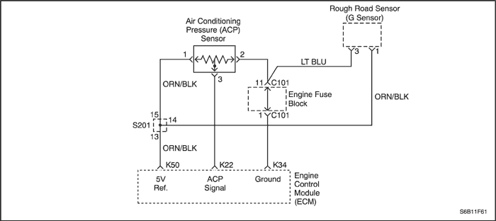
The Air Conditioning (A/C) system uses an A/C refrigerant pressure sensor mounted in the high pressure side of the A/C refrigerant system to monitor A/C refrigerant pressure. The Engine Control Module (ECM) uses this information to turn ON the engine coolant fans when the A/C refrigerant pressure is high and to keep the compressor disengaged when A/C refrigerant pressure is excessively high or low.
The Air Conditioning Pressure (ACP) sensor operates like other 3-wire sensors. The ECM applies a 5.0 volt reference and a sensor ground to the sensor. Changes in the A/C refrigerant pressure will cause the ACP sensor input to the ECM to vary. The ECM monitors the ACP sensor signal circuit and can determine when the signal is outside of the possible range of the sensor. When the signal is out of range for a prolonged period of time, the ECM will not allow the A/C compressor clutch to engage. This is done to protect the compressor.
Conditions for Setting the DTC
- A/C pressure is less than 1 % of the sensor reading scale.
- Engine is running.
Action Taken When the DTC Sets
- The Malfunction Indicator Lamp (MIL) will not illuminate.
- The ECM will record operating conditions at the time the diagnostic fails. This information will be stored in the Failure Records buffers.
- A history DTC is stored.
- The A/C compressor operation will be disabled while the low voltage indication exists.
Conditions for Clearing the MIL/DTC
- A history DTC will clear after 40 consecutive warm-up cycles without a fault.
- DTC(s) can be cleared by using the scan tool.
- Disconnecting the ECM battery feed for more than 10 seconds.
Diagnostic Aids
Inspect harness connectors for backed-out terminals, improper mating, broken locks, improperly formed or damaged terminals, and poor terminal-to-wire connection at the ECM.
Inspect the wiring harness for damage. If the harness appears to be OK, observe the A/C pressure display on the scan tool while moving the connectors and wiring harnesses related to the A/C Pressure sensor. A change in the A/C pressure display will indicate the location of the fault.
If DTC P0532 cannot be duplicated, reviewing the Fail Records vehicle mileage since the diagnostic test last failed may help determine how often the condition that caused the DTC to set occurs. This may assist in diagnosing the condition.
DTC P0532 - Air Conditioning (A/C) Refrigerant Pressure Sensor Circuit Low Voltage
| Step | Action | Value(s) | Yes | No |
| 1 | Perform an On-Board Diagnostic (EOBD) System Check. Was the check performed? | - | Go to Step 2 | |
| 2 | - Install a scan tool to the Data Link Connector (DLC).
- Idle the engine.
Does the scan tool display Air Conditioning Pressure (ACP) sensor voltage below the specified value? | 0.06 V | Go to Step 3 | Go to Step 4 |
| 3 | - Turn the ignition OFF.
- Disconnect the ACP sensor connector.
- Jumper the ACP signal circuit, terminal 2 to the 5 volt reference circuit, terminal 1.
- Turn the ignition switch on.
Does the ACP voltage read more than the specified value? | 4.9 V | Go to Step 5 | Go to Step 6 |
| 4 | - Turn the ignition ON, with the engine OFF.
- Operate the vehicle within the Failure Record conditions and Conditions For Setting the DTC as noted.
Does the scan tool display ACP voltage below the specified value? | 0.06 V | Go to Step 3 | |
| 5 | Inspect the ACP sensor harness connector terminals for the following conditions: - Poor connections
- Proper contact tension
- Poor terminal-to-wire connection
Is a problem found? | - | Go to Step 8 | Go to Step 9 |
| 6 | - Turn the ignition OFF.
- Remove the jumper wire.
- Probe the ACP sensor signal circuit terminal 2 with a test light to B+.
- Turn the ignition ON.
Does the scan tool read over the specified value? | 4 V | Go to Step 7 | Go to Step 11 |
| 7 | Check the ACP sensor 5 volt reference circuit for an open or short to ground and repair as needed. Is the repair complete? | - | Go to Step 13 | Go to Step 10 |
| 8 | Repair the connection terminals as necessary. Is the repair complete? | - | Go to Step 13 | - |
| 9 | - Turn the ignition OFF.
- Replace the ACP sensor.
Is the repair complete? | - | Go to Step 13 | - |
| 10 | - Turn the ignition OFF.
- Replace the engine control module (ECM).
Is the repair complete? | - | Go to Step 13 | - |
| 11 | Check the ACP sensor signal circuit for the following conditions: - Open
- Short to ground
- Short to sensor ground
Is a problem found? | - | Go to Step 12 | Go to Step 10 |
| 12 | Repair the A/C Pressure sensor signal circuit. Is the repair complete? | - | Go to Step 13 | - |
| 13 | - Using the scan tool, clear the Diagnostic Trouble Codes (DTCs).
- Start the engine and idle at normal operating temperature.
- Operate the vehicle within the Conditions for setting this DTC as specified in the supporting text.
Does the scan tool indicate that this diagnostic has run and passed? | - | Go to Step 14 | Go to Step 2 |
| 14 | Check if any additional DTCs are set. Are any DTCs displayed that have not been diagnosed? | - | Go to Applicable DTC table | System OK |
Diagnostic Trouble Code (DTC) P0533
Air Conditioning (A/C) Refrigerant Pressure Sensor Circuit High Voltage
Circuit Description
The Air Conditioning (A/C) system uses an A/C refrigerant pressure sensor mounted in the high pressure side of the A/C refrigerant system to monitor A/C refrigerant pressure. The Engine Control Module (ECM) uses this information to turn ON the engine coolant fans when the A/C refrigerant pressure is high and to keep the compressor disengaged when A/C refrigerant pressure is excessively high or low.
The Air Conditioning Pressure (ACP) sensor operates like other 3-wire sensors. The ECM applies a 5.0 volt reference and a sensor ground to the sensor. Changes in the A/C refrigerant pressure will cause the ACP sensor input to the ECM to vary. The ECM monitors the ACP sensor signal circuit and can determine when the signal is outside of the possible range of the sensor. When the signal is out of range for a prolonged period of time, the ECM will not allow the A/C compressor clutch to engage. This is done to protect the compressor.
Conditions for Setting the DTC
- A/C pressure is greater than 99% of the sensor reading scale.
- Engine is running.
Action Taken When the DTC Sets
- The Malfunction Indicator Lamp (MIL) will not illuminate.
- The ECM will record operating conditions at the time the diagnostic fails. This information will be stored in the Failure Records buffers.
- A history DTC is stored.
- The A/C compressor operation will be disabled while the high voltage indication exists.
Conditions for Clearing the MIL/DTC
- A history DTC will clear after 40 consecutive warm-up cycles without a fault.
- DTC(s) can be cleared by using the scan tool.
- Disconnecting the ECM battery feed for more than 10 seconds.
Diagnostic Aids
Inspect harness connectors for backed-out terminals, improper mating, broken locks, improperly formed or damaged terminals, and poor terminal-to-wire connection at the ECM.
Inspect the wiring harness for damage. If the harness appears to be OK, observe the A/C pressure display on the scan tool while moving the connectors and wiring harnesses related to the ACP sensor. A change in the A/C pressure display will indicate the location of the fault.
If DTC P0533 cannot be duplicated, reviewing the Fail Records vehicle mileage since the diagnostic test last failed may help determine how often the condition that caused the DTC to set occurs. This may assist in diagnosing the condition.
DTC P0533 - Air Conditioning (A/C) Refrigerant Pressure Sensor Circuit High Voltage
| Step | Action | Value(s) | Yes | No |
| 1 | Perform an On-Board Diagnostic (EOBD) System Check. Was the check performed? | - | Go to Step 2 | |
| 2 | - Install a scan tool to the Data Link Connector (DLC).
- Idle the engine.
Does the scan tool display Air Conditioning Pressure (ACP) sensor voltage below the specified value? | 0.06 V | Go to Step 3 | Go to Step 4 |
| 3 | - Turn the ignition OFF.
- Disconnect the ACP sensor connector.
- Jumper the ACP signal circuit, terminal 2 to the 5 volt reference circuit, terminal 1.
- Turn the ignition switch on.
Does the ACP voltage read more than the specified value? | 4.9 V | Go to Step 5 | Go to Step 6 |
| 4 | - Turn the ignition ON, with the engine OFF.
- Operate the vehicle within the Failure Record conditions and Conditions For Setting the DTC as noted.
Does the scan tool display ACP voltage below the specified value? | 0.06 V | Go to Step 3 | |
| 5 | Inspect the ACP sensor harness connector terminals for the following conditions: - Poor connections
- Proper contact tension
- Poor terminal-to-wire connection
Is a problem found? | - | Go to Step 8 | Go to Step 9 |
| 6 | - Turn the ignition OFF.
- Remove the jumper wire.
- Probe the ACP sensor signal circuit terminal 2 with a test light to B+.
- Turn the ignition ON.
Does the scan tool read over the specified value? | 4 V | Go to Step 7 | Go to Step 11 |
| 7 | Check the ACP sensor 5 volt reference circuit for an open or short to ground and repair as needed. Is the repair complete? | - | Go to Step 13 | Go to Step 10 |
| 8 | Repair the connection terminals as necessary. Is the repair complete? | - | Go to Step 13 | - |
| 9 | - Turn the ignition OFF.
- Replace the ACP sensor.
Is the repair complete? | - | Go to Step 13 | - |
| 10 | - Turn the ignition OFF.
- Replace the engine control module (ECM).
Is the repair complete? | - | Go to Step 13 | - |
| 11 | Check the ACP sensor signal circuit for the following conditions: - Open
- Short to ground
- Short to sensor ground
Is a problem found? | - | Go to Step 12 | Go to Step 10 |
| 12 | Repair the A/C Pressure sensor signal circuit. Is the repair complete? | - | Go to Step 13 | - |
| 13 | - Using the scan tool, clear the Diagnostic Trouble Codes (DTCs).
- Start the engine and idle at normal operating temperature.
- Operate the vehicle within the Conditions for setting this DTC as specified in the supporting text.
Does the scan tool indicate that this diagnostic has run and passed? | - | Go to Step 14 | Go to Step 2 |
| 14 | Check if any additional DTCs are set. Are any DTCs displayed that have not been diagnosed? | - | Go to Applicable DTC table | System OK |
Diagnostic Trouble Code (DTC) P0562
System Voltage Low
Circuit Description
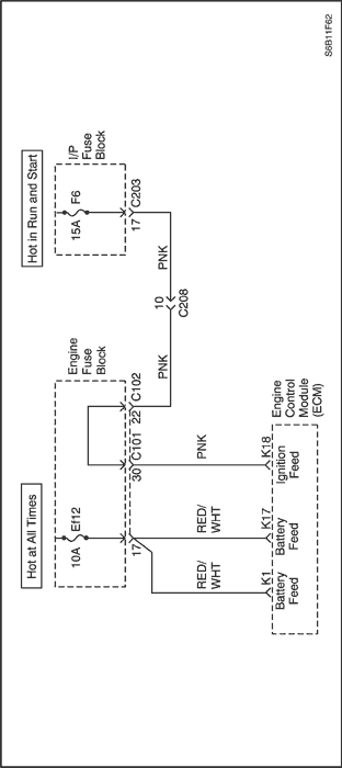
The Engine Control Module (ECM) monitors the ignition voltage on the ignition feed circuit to terminal K18 at the ECM. A system voltage Diagnostic Trouble Code (DTC) will set whenever the voltage is below a calibrated value.
Conditions for Setting the DTC
- System voltage is less than 11 volts.
- Engine is running.
Action Taken When the DTC Sets
- The Malfunction Indicator Lamp (MIL) will not illuminate.
- The ECM will record operating conditions at the time the diagnostic fails. This information will be stored in the Failure Records buffers.
- A history DTC is stored.
Conditions for Clearing the MIL/DTC
- A history DTC will clear after 40 consecutive warm-up cycles without a fault.
- DTC(s) can be cleared by using the scan tool.
- Disconnecting the ECM battery feed for more than 10 seconds.
Diagnostic Aids
If the DTC sets when an accessory is operated, check for a poor connection or excessive current draw.
Any circuitry, that is suspected as causing the intermittentcomplaint, should be thoroughly checked for the followingconditions:
- Backed-out terminals
- Improper mating
- Broken locks
- Improperly formed
- Damaged terminals
- Poor terminal-to-wiring connections
- Physical damage to the wiring harness
Test Description
Number(s) below refer to the step number(s) on the Diagnostic Table.
- The On-Board Diagnostic (EOBD) System Check prompts the technician to complete some basic checks and store the freeze frame and failure records data on the scan tool if applicable. This creates an electronic copy of the data taken when the malfunction occurred. The information is then stored on the scan tool for later reference.
- This checks if the generator is malfunctioning under load conditions.
- Checks the ignition feed circuit for excessive resistance. An open circuit will cause a no start condition.
- The replacement ECM must be reprogrammed. Refer to the latest Techline procedure for ECM reprogramming.
- If no malfunctions have been found at this point and no additional DTCs were set, refer to "Diagnostic Aids" in this section for additional checks and information for additional checks and information.
DTC P0562 - System Voltage Low
| Step | Action | Value(s) | Yes | No |
| 1 | Perform an On-Board Diagnostic (EOBD) System Check. Was the check performed? | - | Go to Step 2 | |
| 2 | - Install a scan tool to the Data Link Connector (DLC) and clear the Diagnostic Trouble Codes (DTCs).
- Start the engine and raise the engine speed over 1400 rpm.
- Load the electrical system by turning on the headlamps, high blower motor, etc.
Is the ignition voltage less than the specified value | 10 V | Go to Step 3 | Go to Step 8 |
| 3 | - With the engine still running at 1400 rpm.
- Using a voltmeter measure the battery voltage at the battery.
Is the battery voltage greater than the specified value? | 12 V | Go to Step 4 | |
| 4 | - Turn the ignition OFF.
- Disconnect the Engine Control Module (ECM) connector at the ECM.
- Turn the ignition ON.
- Using a voltmeter, measure the voltage at the ignition feed circuit, terminal K18.
Is the ignition voltage greater than the specified value? | 10 V | Go to Step 5 | Go to Step 6 |
| 5 | Check for a malfunctioning connector at the ECM harness terminals and repair as needed. Is the repair complete? | - | Go to Step 8 | Go to Step 7 |
| 6 | Repair the poor connection (high resistance) in the ignition feed circuit. Is the repair complete? | - | Go to Step 8 | - |
| 7 | - Turn the ignition OFF.
- Replace the ECM.
Is the repair complete? | - | Go to Step 8 | - |
| 8 | - Using the scan tool, clear the Diagnostic Trouble Codes (DTCs).
- Start the engine and idle at normal operating temperature.
- Operate the vehicle within the Conditions for setting this DTC as specified in the supporting text.
Does the scan tool indicate that this diagnostic has run and passed? | - | Go to Step 9 | Go to Step 2 |
| 9 | Check if any additional DTCs are set. Are any DTCs displayed that have not been diagnosed? | - | Go to Applicable DTC table | System OK |
Diagnostic Trouble Code (DTC) P0563
System Voltage High
Circuit Description
The Engine Control Module (ECM) monitors the ignition voltage on the ignition feed circuit to terminal K18 at the ECM. A system voltage Diagnostic Trouble Code (DTC) will set whenever the voltage is above a calibrated value.
Conditions for Setting the DTC
- System voltage is greater than 16 volts.
- Engine is running.
Action Taken When the DTC Sets
- The Malfunction Indicator Lamp (MIL) will not illuminate.
- The ECM will record operating conditions at the time the diagnostic fails. This information will be stored in the Failure Records buffers.
- A history DTC is stored.
Conditions for Clearing the MIL/DTC
- A history DTC will clear after 40 consecutive warm-up cycles without a fault.
- DTC(s) can be cleared by using the scan tool.
- Disconnecting the ECM battery feed for more than 10 seconds.
Diagnostic Aids
If the DTC sets when an accessory is operated, check for a poor connection or excessive current draw.
Any circuitry, that is suspected as causing the intermittent complaint, should be thoroughly checked for the following conditions:
- Backed-out terminals
- Improper mating
- Broken locks
- Improperly formed
- Damaged terminals
- Poor terminal-to-wiring connections
- Physical damage to the wiring harness
Test Description
Number(s) below refer to the step number(s) on the Diagnostic Table.
- The On-Board Diagnostic (EOBD) System Check prompts the technician to complete some basic checks and store the freeze frame and failure records data on the scan tool if applicable. This creates an electronic copy of the data taken when the malfunction occurred. The information is then stored on the scan tool for later reference.
- This checks if the generator is malfunctioning under load conditions.
- The replacement ECM must be reprogrammed. Refer to the latest Techline procedure for ECM reprogramming.
- If no malfunctions have been found at this point and no additional DTCs were set, refer to "Diagnostic Aids" in this section for additional checks and information for additional checks and information.
DTC P0563 - System Voltage High
| Step | Action | Value(s) | Yes | No |
| 1 | Perform an On-Board Diagnostic (EOBD) System Check. Was the check performed? | - | Go to Step 2 | |
| 2 | - Install a scan tool to the Data Link Connector (DLC) and clear the Diagnostic Trouble Codes (DTCs).
- Start the engine and raise the engine speed over 1400 rpm.
- Load the electrical system by turning on the headlamps, high blower motor, etc.
Is the ignition voltage less than the specified value | 16 V | Go to Step 3 | Go to Step 5 |
| 3 | - With the engine still running at 1400 rpm.
- Using a voltmeter measure the battery voltage at the battery.
Is the battery voltage less than the specified value? | 16 V | Go to Step 4 | |
| 4 | - Turn the ignition OFF.
- Replace the ECM.
Is the repair complete? | - | Go to Step 5 | - |
| 5 | - Using the scan tool, clear the Diagnostic Trouble Codes (DTCs).
- Start the engine and idle at normal operating temperature.
- Operate the vehicle within the conditions for setting this DTC as specified in the supporting text.
Does the scan tool indicate that this diagnostic has run and passed? | - | Go to Step 6 | Go to Step 2 |
| 6 | Check if any additional DTCs are set. Are any DTCs displayed that have not been diagnosed? | - | Go to Applicable DTC table | System OK |
Diagnostic Trouble Code (DTC) P0601
Control Module Read Only Memory (ROM)
Circuit Description
The Engine Control Module (ECM) is the control center of the fuel injection system. It constantly looks at the information from various sensors, and controls the systems that affect vehicle performance. The ECM also performs the diagnostic function of the system. It can recognize operational problems, alert the driver through the Malfunction Indicator Lamp (MIL) (Check Engine), and store a Diagnostic Trouble Code (DTC) or DTCs which identify the problem areas to aid the technician in making repairs. An Electrically Erasable Programmable Read Only Memory (EEPROM) is used to house the program information and the calibrations required for engine, transmission, and powertrain diagnostics operation. The ECM uses a value called a checksum for error detection of the software. The checksum is a value that is equal to all the numbers in the software added together. The ECM adds all the values in the software, and if that value does not equal the checksum value, a checksum error is indicated.
Conditions for Setting the DTC
- Program ID is not equal to the value in the software.
- Ignition switch is turned to ON.
Action Taken When the DTC Sets
- The Malfunction Indicator Lamp (MIL) will illuminate.
- The ECM will attempt to record operating conditions at the time the failure is detected. However, since this is the internal ECM fault, this information may be or may not be reliable. This information will be stored in the freeze Frame and Failure Records buffers.
- A history DTC is stored.
Conditions for Clearing the MIL/DTC
- The MIL turn off after four consecutive ignition cycles in which the diagnostic runs without a fault.
- A history DTC will clear after 40 consecutive warm-up cycles without a fault.
- DTC(s) can be cleared by using the scan tool.
- Disconnecting the ECM battery feed for more than 10 seconds.
Test Description
Number(s) below refer to the step number(s) on the Diagnostic Table.
- The On-Board Diagnostic (EOBD) System Check prompts the technician to complete some basic checks and store the freeze frame and failure records data on the scan tool if applicable. This creates an electronic copy of the data taken when the malfunction occurred. The information is then stored on the scan tool for later reference.
- The replacement ECM must be reprogrammed. Refer to the latest Techline procedure for ECM reprogramming.
DTC P0601 - Control Module Read Only Memory (ROM)
| Step | Action | Value(s) | Yes | No |
| 1 | Perform an On-Board Diagnostic (EOBD) System Check. Was the check performed? | - | Go to Step 2 | |
| 2 | - Turn the ignition OFF.
- Replace the Engine Control Module (ECM).
Is the repair complete? | - | Go to Step 3 | - |
| 3 | - Using the scan tool, clear the Diagnostic Trouble Codes (DTCs).
- Start the engine and idle at normal operating temperature.
- Operate the vehicle within the conditions for setting this DTC as specified in the supporting text.
Does the scan tool indicate that this diagnostic has run and passed? | - | Go to Step 4 | Go to Step 2 |
| 4 | Check if any additional DTCs are set. Are any DTCs displayed that have not been diagnosed? | - | Go to Applicable DTC table | System OK |
Diagnostic Trouble Code (DTC) P0602
Control Module Not Programmed
Circuit Description
The Engine Control Module (ECM) is the control center of the fuel injection system. It constantly looks at the information from various sensors, and controls the systems that affect vehicle performance. The ECM also performs the diagnostic function of the system. It can recognize operational problems, alert the driver through the Malfunction Indicator Lamp (MIL) (Check Engine), and store a Diagnostic Trouble Code (DTC) or DTCs which identify the problem areas to aid the technician in making repairs. An Electrically Erasable Programmable Read Only Memory (EEPROM) is used to house the program information and the calibrations required for engine, transmission, and powertrain diagnostics operation. The ECM uses a value called a checksum for error detection of the software. The checksum is a value that is equal to all the numbers in the software added together. The ECM changes the checksum after reprogramming and adds all the values in the software, and if that value does not equal the checksum value, a ECM reprogramming error is indicated.
Conditions for Setting the DTC
- Calibration ID is not equal to the value in the software level.
- S/W major ID not equal to value in S/W.
Action Taken When the DTC Sets
- The Malfunction Indicator Lamp (MIL) will illuminate.
- The ECM will attempt to record operating conditions at the time the failure is detected. However, since this is the internal ECM fault, this information may be or may not be reliable. This information will be stored in the freeze Frame and Failure Records buffers.
- A history DTC is stored.
Conditions for Clearing the MIL/DTC
- The MIL turn off after four consecutive ignition cycles in which the diagnostic runs without a fault.
- A history DTC will clear after 40 consecutive warm-up cycles without a fault.
- DTC(s) can be cleared by using the scan tool.
- Disconnecting the ECM battery feed for more than 10 seconds.
DTC P0602 - Control Module Not Programmed
| Step | Action | Value(s) | Yes | No |
| 1 | Perform an On-Board Diagnostic (EOBD) System Check. Was the check performed? | - | Go to Step 2 | |
| 2 | - Turn the ignition OFF.
- Replace the Engine Control Module (ECM).
Is the repair complete? | - | Go to Step 3 | - |
| 3 | - Using the scan tool, clear the Diagnostic Trouble Codes (DTCs).
- Start the engine and idle at normal operating temperature.
- Operate the vehicle within the Conditions for setting this DTC as specified in the supporting text.
Does the scan tool indicate that this diagnostic has run and passed? | - | Go to Step 4 | Go to Step 2 |
| 4 | Check if any additional DTCs are set. Are any DTCs displayed that have not been diagnosed? | - | Go to Applicable DTC Table | System OK |
| © Copyright Chevrolet Europe. All rights reserved |