Diagnostic Trouble Code (DTC) P0606
Control Module Internal Performance
Circuit Description
The Engine Control Module (ECM) is the control centerof the fuel injection system. It constantly looks at the informationfrom various sensors, and controls the systemsthat affect vehicle performance. The ECM alsoperforms the diagnostic function of the system. It canrecognize operational problems, alert the driver throughthe Malfunction Indicator Lamp (MIL) (Check Engine),and store a Diagnostic Trouble Code (DTC) or DTCswhich identify the problem areas to aid the technician inmaking repairs. An Electrically Erasable ProgrammableRead Only Memory (EEPROM) is used to house theprogram information and the calibrations required forengine, transmission, and powertrain diagnostics operation.The Diagnostic Trouble Code (DTC) will stored,when the ECM detects SPI communication betweenmain CPU and output driver I/C is corrupted.
Conditions for Setting the DTC
- Ignition switch is turned to ON.
- Battery voltage is greater than 11 volts.
- ECM detects that SPI communication between main CPU and output driver I/C is corrupted.
Action Taken When the DTC Sets
- The Malfunction Indicator Lamp (MIL) will illuminate.
- The ECM will record operating conditions at the timethe diagnostic fails. This information will be stored inthe Freeze Frame and Failure Records buffers.
- A history DTC is stored.
Conditions for Clearing the MIL/DTC
- A history DTC will clear after 40 consecutive warm-up cycles without a fault.
- DTC(s) can be cleared by using the scan tool.
- Disconnecting the ECM battery feed for more than 10seconds.
DTC P0606 - Control Module Internal Performance
| Step | Action | Value(s) | Yes | No |
| 1 | Perform an On-Board Diagnostic (EOBD) System Check. Was the check performed? | - | Go to Step 2 | |
| 2 | - Turn the ignition OFF.
- Replace the Engine Control Module (ECM).
Is the repair complete? | - | Go to Step 3 | - |
| 3 | - Using the scan tool, clear the Diagnostic TroubleCodes (DTCs).
- Start the engine and idle at normal operatingtemperature.
- Operate the vehicle within the Conditions forsetting this DTC as specified in the supportingtext.
Does the scan tool indicate that this diagnostic hasrun and passed? | - | Go to Step 4 | Go to Step 2 |
| 4 | Check if any additional DTCs are set. Are any DTCs displayed that have not beendiagnosed? | - | Go to Applicable DTC table | System OK |
Diagnostic Trouble Code (DTC) P0660
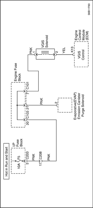
Intake Manifold Tuning (IMT) Valve Solenoid Control Circuit
Circuit Description
The Engine Control Module(ECM) operates a solenoid to control the Intake manifold Tuning (IMT) valve solenoid electrical. The solenoid is normally closed. By providing a ground path, the ECM energizes the solenoid.
Conditions for Setting the DTC
- Engine is running.
- ECM detects open or short circuits.
Action Taken When the DTC Sets
- The Malfunction Indicator Lamp (MIL) not will illuminate.
- The ECM will record operating conditions at the time the diagnostic fails. The information will be stored in the freeze frame and failure records buffers.
- A history DTC is stored.
Conditions for Clearing the MIL/DTC
- A history DTC will clear after 40 consecutive warm up cycles without a fault.
- DTC(s) can be cleared by using the scan tool.
Diagnostic Aids
An intermittent problem may be caused by a poor connection, rubbed-through wire insulation, or a wire that is broken inside the insulation.
DTC P0660 - Intake Manifold Tuning (IMT) Valve Solenoid Control Circuit
| Step | Action | Value(s) | Yes | No |
| 1 | Perform an On - Board Diagnostic (OBD) System Check. Is the system check complete? | - | Go to Step 2 | |
| 2 | - Turn the ignition switch to LOCK.
- Disconnect the Intake Manifold Tuning (IMT) valve solenoid connector.
- Measure the resistance of the IMT valve solenoid.
Does the resistance near the specified value? | 0 Ω | Go to Step 3 | Go to Step 6 |
| 3 | - Disconnect the main relay connector.
- Check for an open or a short to ground in the wire between the IMT valve solenoid connector terminal 1 and the I/P fuse block connector.
Is the problem found? | - | Go to Step 4 | Go to Step 5 |
| 4 | Repair the wire and the connector terminal. Is the repair complete? | - | Go to Step 8 | - |
| 5 | - Turn the ignition switch to LOCK.
- Disconnect the Engine Control Module(ECM) connector.
- Check for an open or a short to ground in the wire between the IMT valve solenoid connector terminal 2 and the ECM connector terminal K13.
Is the problem found? | - | Go to Step 4 | Go to Step 7 |
| 6 | Replace the IMT valve solenoid. Is the replacement complete? | - | Go to Step 8 | - |
| 7 | Replace the ECM. Is the replacement complete? | - | Go to Step 9 | - |
| 8 | - Using the scan tool, clear the Diagnostic Trouble Codes (DTCs).
- Start the engine.
- Run the engine until it reaches normal operating temperature at idle.
- Operating the vehicle within the conditions for setting this DTC as specified in the supporting text.
Does the scan tool indicate that this diagnostic has run and passed? | - | Go to Step 9 | Go to Step 2 |
| 9 | Check if any additional DTCs are set. Are any DTCs displayed that have not been diagnosed? | - | Go to applicable DTC table | System OK |
Diagnostic Trouble Code (DTC) P0700
Transmission Control Module (TCM) Requested MIL Illumination
Circuit Description
The Transmission Control Module (TCM) and the Engine Control Module (ECM) are connected through the serial data link circuit. The TCM sends a Class-II P-code status message to the ECM every 100 milliseconds to confirm the transmission is functioning correctly.
If the TCM detects either an A- or B-type malfunction within the transmission, the TCM will send to the ECM a P-code status message to turn the Malfunction Indicator Lamp (MIL) ON and set DTC P0700.
Conditions for Setting the DTC
- Received message from the TCM indicating malfunction is detected in TCM.
Action Taken When the DTC Sets
- The Malfunction Indicator Lamp (MIL) will illuminate.
- The ECM will record operating conditions at the time the diagnostic fails. This information will be stored in the Freeze Frame and/or Failure Records buffers.
- A history DTC is stored.
Conditions for Clearing the MIL/DTC
- A history DTC will clear after 40 consecutive warm-up cycles without a fault.
- DTC(s) can be cleared by using the scan tool.
- Disconnecting the ECM battery feed for more than 10 seconds.
Diagnostic Aids
An intermittent may be caused by a poor connection, rubbed-through wire insulation or a wire broken inside the insulation.
Check for a poor connection or damaged ECM/TCM harness. Inspect the serial data link circuit for the following conditions:
- Improper mating
- Broken locks
- Improperly formed
- Damaged terminals
- Poor terminal-to-wiring connections
- Damaged harness
DTC P0700 - Transmission Control Module (TCM) Requested MIL Illumination
| Step | Action | Value(s) | Yes | No |
| 1 | Perform an On-Board Diagnostic (EOBD) System Check. Was the check performed? | - | Go to Step 2 | |
| 2 | - Install a scan tool to the Data Link Connector (DLC).
- Turn the ignition ON.
- Select Transmission Control Module (TCM) Diagnostic Trouble Code (DTC) with scan tool.
Is a transmission DTC displayed? | - | Go to Step 3 | Go to Step 4 |
| 3 | - Repair transmission malfunction. Refer to the applicable DTC table in the transmission repair section.
- Using a scan tool, clear the TCM DTC.
Is the repair complete? | - | Go to Step 4 | - |
| 4 | - Using the scan tool, clear the Diagnostic Trouble Codes (DTCs).
- Start the engine and idle at normal operating temperature.
- Operate the vehicle within the Conditions for setting this DTC as specified in the supporting text.
Does the scan tool indicate that this diagnostic has run and passed? | - | Go to Step 5 | Go to Step 2 |
| 5 | Check if any additional DTCs are set. Are any DTCs displayed that have not been diagnosed? | - | Go to Applicable DTC Table | System OK |
 | |  | |
| © Copyright Chevrolet Europe. All rights reserved |