Diagnostic Trouble Code (DTC) P1133
HO2S Insufficient Switching Sensor 1
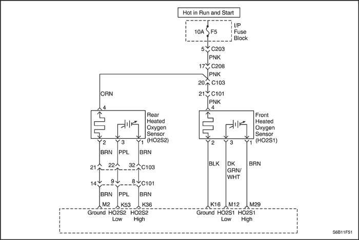
Circuit Description
The Engine Control Module (ECM) continuously monitors the Front Heated Oxygen Sensor (HO2S1) activity for 100 seconds. During the monitor period, the ECM counts the number of times that the HO2S1 switches from rich to lean and from lean to rich. With this information, a total for all switches can be determined. If the number of switches is too low, a Diagnostic Trouble code (DTC) P1133 will set. The lean-to-rich and rich-to-lean are less than 15 switches.
Conditions for Setting the DTC
- HO2S1 signal switches from 0.3 to 0.6 volts and 0.6 to 0.3 volts is less than 10 times within 90seconds.
- Closed loop stoichiometry.
- Engine Coolant Temperature (ECT) is greater than 70 °C (158 °F).
- System voltage is greater than 10 volts.
- Engine run time is greater than 60 seconds.
- Purge Duty Cycle (DC) is less than 20%.
- The rpm is between 1500 and 3000.
- Airflow is between 9 and 30 g/sec.
- DTCs P0106, P0107, P0108, P0117, P0118, P0122, P0123, P0131, P0132, P0134, P0135, P0171, P0172, P0201, P0202, P0203, P0204, P0300, P0336, P0351, P0352, P0402, P0404, P0405, P0406, P0506, P0507, and P0443 are not set.
- 3 second delay after conditions are met.
Action Taken When the DTC Sets
- The Malfunction Indicator Lamp (MIL) will illuminate, after three consecutive ignition cycle with a fail.
- The ECM will record operating conditions at the time the diagnostic fails. This information will be stored in the Freeze Frame and Failure Records buffers.
- A history DTC is stored.
Conditions for Clearing the MIL/DTC
- The MIL will turn off after four consecutive ignition cycles in which the diagnostic runs without a fault.
- A history DTC will clear after 40 consecutive warm-up cycles without a fault.
- DTC can be cleared by using the scan tool.
- Disconnecting the ECM battery feed for more than 10 seconds.
Diagnostic Aids
DTC P1133 is most likely caused by one of the following items:
- Fuel Pressure - The system will go rich if the fuel pressure is too high. The ECM can compensate for some increase. However, if it gets too high, a DTC P1133 may set. Refer to "Fuel System Diagnosis" in this section.
- Leaking injector - A leaking or malfunctioning injector can cause the system to go rich.
- Manifold Absolute Pressure (MAP) sensor - An output that causes the ECM to sense a higher than normal manifold pressure (low vacuum) can cause the system to go rich. Disconnecting the MAP sensor will allow the ECM to set a fixed value for the MAP sensor. Substitute a different MAP sensor if the rich condition is gone while the sensor is disconnected.
- Pressure regulator - Check for a leaking fuel pressure regulator diaphragm by checking for the presence of liquid fuel in the vacuum line to the pressure regulator.
- Throttle Position (TP) sensor - An intermittent TP sensor output can cause the system to go rich due to a false indication of the engine accelerating.
- HO2S1 contamination - Inspect the HO2S1 for silicone contamination from fuel or improper use of Room Temperature Vulcanizing (RTV) sealant. The sensor may have a white powdery coating and result in a high but false voltage signal (rich exhaust indication). The ECM will then reduce the amount of fuel delivered to the engine causing a severe surge or driveability problem.
Test Description
Number(s) below refer to the step number(s) on the Diagnostic Chart.
- The On-Board Diagnostic (EOBD) System Check prompts the technician to complete some basic checks and store the freeze frame and failure records data on the scan tool if applicable. This creates an electronic copy of the data taken when the malfunction occurred. The information is then stored on the scan tool for later reference.
- The replacement ECM must be reprogrammed. Refer to the latest Techline procedure for ECM reprogramming.
- If no malfunctions have been found at this point and no additional DTCs are set, refer to "Diagnostic Aids" in this section for additional checks and information.
DTC P1133 - HO2S Insufficient Switching Sensor 1
| Step | Action | Value(s) | Yes | No |
| 1 | Perform an On-Board Diagnostic (EOBD) System Check. Was the check performed? | - | Go to Step 2 | |
| 2 | - Install a scan tool to the Data Link Connector (DLC).
- Turn the ignition ON.
Are any additional Diagnostic Trouble Codes (DTCs) set? | - | Go to applicable DTC table | Go to Step 3 |
| 3 | - Start the engine and idle at normal operating temperature.
- Operate the vehicle within the specified parameter under the Conditions For Setting the DTC.
- Monitor the lean-to-rich transition and rich-to-lean transition and note the number of switches.
Does the parameter show fewer transitions than the specified value within 90 seconds. | 15 | Go to Step 4 | Go to Step 18 |
| 4 | Visually/physically inspect for the following items: - Front Heated Oxygen Sensor (HO2S1) is securely installed.
- Corrosion on the terminals.
- Terminal tension.
- HO2S1 wiring harness for poor terminal connection or damaged wiring.
Is a problem found in any of the above areas? | - | Go to Step 9 | Go to Step 5 |
| 5 | Check the exhaust manifold for a leak near the engine and repair as needed. Is the repair complete? | - | Go to Step 3 | Go to Step 6 |
| 6 | - Turn the ignition OFF.
- Disconnect the HO2S1 connector.
- Jumper the HO2S1 low circuit, terminal 2 to ground.
- Turn the ignition ON.
Does the scan tool indicate the voltage between the specified value? | 400-500 mV | Go to Step 7 | Go to Step 10 |
| 7 | Jumper the HO2S1 signal and low circuit terminal 4 to ground. Does the scan tool indicate the voltage below the specified value? | 200 mV | Go to Step 8 | Go to Step 11 |
| 8 | - Turn the ignition OFF.
- Replace the HO2S1.
Note : before replacing the sensor, the cause of the contamination must be determined and corrected in order to prevent further damage to the sensor. Check for following: - Fuel contamination.
- Use of improper Room Temperature Vulcanizing sealant.
- Engine oil/coolant consumption.
Is the repair complete? | - | Go to Step 15 | - |
| 9 | Repair the condition as needed. Is the repair complete? | - | Go to Step 15 | - |
| 10 | Repair the HO2S1 signal circuit for a short to ground. Is the repair complete? | - | Go to Step 15 | - |
| 11 | - Remove the jumper wire.
- Using voltmeter measure the voltage between the HO2S1 signal circuit, terminal 4 and ground.
Does the voltage above the specified value? | 407 mV | Go to Step 12 | Go to Step 13 |
| 12 | - Turn the ignition OFF.
- Disconnect the ECM connectors and check the continuity between terminal 1 of HO2S1 and the terminal M29 of the ECM.
- If the circuit measures over the specified value, repair open or poor connection as needed.
Is the repair complete? | 5 Ω | Go to Step 15 | Go to Step 14 |
| 13 | - Turn the ignition OFF.
- Check the continuity between terminal 4 of HO2S1 and the terminal M12 of the ECM.
- If the circuit measures over the specified value, repair open or poor connection as needed.
Is the repair complete? | 5 Ω | Go to Step 15 | Go to Step 14 |
| 14 | - Turn the ignition OFF.
- Replace the ECM.
Is the repair complete? | - | Go to Step 15 | - |
| 15 | - Using the scan tool, clear the Diagnostic Trouble Codes (DTCs).
- Start the engine and idle at normal operating temperature.
- Operate the vehicle within the Conditions for setting this DTC as specified in the supporting text.
Does the scan tool indicate that this diagnostic has run and passed? | - | Go to Step 16 | Go to Step 2 |
| 16 | Check if any additional DTCs are set. Are any DTCs displayed that have not been diagnosed? | - | Go to Applicable DTC table | System OK |
Diagnostic Trouble Code (DTC) P1134
HO2S Transition Time Ratio Sensor 1
Circuit Description
The Engine Control Module (ECM) monitors the Front Heated Oxygen Sensor (HO2S1) activity for 100 seconds after closed loop and stoichiometric operation have been established. During the monitoring period the ECM counts the number of times that the HO2S1 responds from rich to lean and adds the amount of time it took to complete all transitions. With this information, an average time for all transitions can be determined. The ECM then divides the -to-lean average by the lean-to-rich average to obtain the ratio. If the HO2S1 transition time ratio is not within the range, Diagnostic Trouble Code (DTC) P1134 will be set, indicating that the HO2S1 is not responding as expected to changes in exhaust oxygen content.
Conditions for Setting the DTC
- HO2S1 rich-to-lean and lean-to rich transition ratio is out of specification(between 0.5 and 1.8).
- Closed Loop stoichiometry.
- Engine Coolant Temperature (ECT) is greater than 70 °C (158 °F).
- System voltage is greater than 10 volts.
- Engine run time is greater than 60 seconds.
- Purge Duty Cycle (DC) is less than 20%.
- Engine speed is between 1500 and 3000 rpm.
- Calculated airflow is between 9 and 30 g/sec.
- DTCs P0106, P0107, P0108, P0117, P0118, P0122, P0123, P0131, P0132, P0134, P0135, P0171, P0172, P0201, P0202, P0203, P0204, P0300, P0336, P0351, P0352, P0402, P0404, P0405, P0406, P0506, P0507, and P0443 are not set.
- 3 second delay after conditions are met.
Action Taken When the DTC Sets
- The Malfunction Indicator Lamp (MIL) will illuminate after three consecutive ignition cycle with a fail.
- The ECM will record operating conditions at the time the diagnostic fails. This information will be stored in the Freeze Frame and Failure Records buffers.
- A history DTC is stored.
- The vehicle will operate in Open Loop.
Conditions for Clearing the MIL/DTC
- The MIL will turn off after four consecutive ignition cycles in which the diagnostic runs without a fault.
- A history DTC will clear after 40 consecutive warm-up cycles without a fault.
- The DTC(s) can be cleared by using the scan tool.
- Disconnecting the ECM battery feed for more than 10 seconds.
Diagnostic Aids
A malfunction in the HO2S1 ignition feed or ground circuit may cause a DTC P1134 to set. Check HO2S1 circuitry for intermittent faults or poor connections. If connections and wiring are OK and DTC P1134 continues to set, replace the HO2S1.
Reviewing the Failure Records vehicle mileage since the diagnostic test last failed may help determine how open the condition that caused the DTC to be set occurs. This may assist in diagnosing the condition.
Test Description
Number(s) below refer to the step number(s) on the Diagnostic Chart.
- A condition that affects pre-converter and post-converter oxygen sensors indicates probable contamination. To avoid damaging replacement sensors, correct the condition which caused the contamination before replacing the affected sensors.
- This step checks for conditions which may cause the oxygen sensor to appear faulty. Correct any of the described conditions if present.
- To avoid damaging replacement sensors, correct the condition which caused the contamination before replacing the affected sensors
DTC P1134 - HO2S Transition Time Ratio Sensor 1
| Step | Action | Value(s) | Yes | No |
| 1 | Perform an On-Board Diagnostic (EOBD) System Check. Was the check performed? | - | Go to Step 2 | |
| 2 | Important : If any Diagnostic Trouble Codes (DTCs) are set, refer to those DTCs before processing with this diagnostic chart. - Install a scan tool to the Data Link Connector (DLC).
- Start the engine and idle at normal operating temperature.
- Operate the engine within parameters specified under Conditions for Setting the DTC.
- Using a scan tool, monitor specific DTC info for DTC P1134 until the DTC P1134 test runs.
- Note the test result.
Does the scan tool indicate DTC P1134 failed this ignition? | - | Go to Step 3 | |
| 3 | Perform an exhaust system leak test. If an exhaust leak is found, repair as needed. The exhaust leak isolated? | - | Go to Step 14 | Go to Step 4 |
| 4 | Visually/physically inspect for the following items: - Front Heated Oxygen Sensor (HO2S1) is securely installed.
- Corrosion on the terminals.
- Terminal tension.
- HO2S1 wiring harness for poor terminal connection or damaged wiring.
Is a problem found in any of the above areas? | - | Go to Step 7 | Go to Step 5 |
| 5 | - Turn the ignition OFF.
- Disconnect the HO2S1 connector.
- Turn the ignition ON.
- Using a voltmeter, measure the voltage between following terminals.
- Terminal 4 of Engine Control Module (ECM) side HO2S1 connector and ground.
- Terminal 2 of ECM side HO2S1 connector and ground.
Are both voltages in the specified value? | 3-5 v | Go to Step 6 | Go to Step 8 |
| 6 | - With the HO2S1 disconnected, jumper the ECM side HO2S1 connector terminals 4 and 2.
- Turn the ignition ON.
- Using a scan tool, monitor the HO2S1 voltage.
Does the scan tool indicates less than 10 millivolts and immediately return to about 450 millivolts when the jumper is removed? | - | Go to Step 10 | Go to Step 9 |
| 7 | Repair conditions as needed. Is the action complete? | - | Go to Step 14 | - |
| 8 | Check for faulty ECM connections or terminal damages and repair as needed. Is the repair complete? | - | Go to Step 14 | Go to Step 9 |
| 9 | Repair open, short, or grounded signal circuit. Is the repair complete? | - | Go to Step 14 | Step 11 |
| 10 | Remove the HO2S1 and examine it for sign of: - Fuel contamination.
- Improper room temperature vulcanizing sealant (white powdery coating on the sensor)
- Engine oil/coolant consumption.
Are sign of contamination observed? | - | Go to Step 12 | Go to Step 13 |
| 11 | - Turn the ignition OFF.
- Replace the ECM.
Is the repair complete? | - | Go to Step 14 | Go to Step 13 |
| 12 | Determine and correct the cause of contamination. Is the repair complete? | - | Go to Step 14 | - |
| 13 | Replace the HO2S1. Is the repair complete? | - | Go to Step 14 | - |
| 14 | - Using the scan tool, clear the Diagnostic Trouble Codes (DTCs).
- Start the engine and idle at normal operating temperature.
- Operate the vehicle within the Conditions for setting this DTC as specified in the supporting text.
Does the scan tool indicate that this diagnostic has run and passed? | - | Go to Step 15 | Go to Step 2 |
| 15 | Check if any additional DTCs are set. Are any DTCs displayed that have not been diagnosed? | - | Go to Applicable DTC table | System OK |
Diagnostic Trouble Code (DTC) P1166
Fuel Trim System Lean During Power Enrichment
System Description
The internal circuitry of the Engine control Module(ECM) can identify if the vehicle fuel system is capableof supplying adequate amounts of fuel during heavy acceleration(power enrichment). When a Power Enrichment(PE) mode of operation is requested by heavyacceleration during Closed Loop operation, the ECM willprovide more fuel to the engine. Under these conditionsthe ECM should detect a rich condition. If this reich conditionis nor detected at this time, Diagnostic TroubleCode (DTC) will set. A plugged fuel filter or restrictedfuel line can prevent adequate amount of fuelfrom being supplied during Power Enrichment mode.
Conditions for Setting the DTC
- HO2S1 voltage is less than 0.35 volts in Power Enrichment(PE) mode.
- Engine is operating in Closed Loop and in PE mode.
- Engine Coolant Temperature (ECT) is greater than60°C (140°F).
- System voltage is greater than 10 volts.
- Air/Fuel ration is less than or equal to 13.5:1.
- DTCs P0106, P0107, P0108, P0117, P0118, P0122,P0123, P0171, P0172, P0201, P0202, P0203,P0204, P0300, P0336, P0351, P0352,P0402, P0404, P0405, P0406, P0506, P0507 and P0443 are not set.
- 3 second delay after in PE mode.
Action Taken When the DTC Sets
- The Malfunction Indicator Lamp (MIL) will illuminate, after two consecutive ignition cycle with a fail.
- The ECM will record operating conditions at the timethe diagnostic fails. This information will be stored inthe Freeze Frame and Failure Records buffers.
- A history DTC is stored.
- The vehicle will operate in Open Loop.
Conditions for Clearing the MIL/DTC
- The MIL will turn off after three consecutive ignition cycles in which the diagnostic runs without a fault.
- A history DTC will clear after 40 consecutive warm-up cycles without a fault.
- DTC(s) can be cleared by using the scan tool.
- Disconnecting the ECM battery feed for more than 10seconds.v
Diagnostic Aids
A restricted fuel filter can supply adequate amounts of fuel at idle, but may not be able to supply enough fuel during heavy acceleration.
Water or alcohol n fuel may cause low HO2S1 voltageduring acceleration.
Check for adequate amount of fuel in the Tank.
When the engine is idling or at steady cruise, the HO2S1voltage should vary from between approximately a00 to900 millivolts. During power enrichment mode, more fuelis needed, and the HO2S1 should rise above 444 millivolts.
Check for faulty or plugged injector(s).
Test Description
Number(s) below refer to the step number(s) on the Diagnostic Table.
- The On-Board Diagnostic (EOBD) System Check prompts the technician to complete some basic checks and store the freeze frame and failure records data on the scan tool if applicable. This creates an electronic copy of the data taken when the malfunction occurred. The information is then stored on the scan tool for later reference.
- This step checks to see if the HO2S1 is operating properly.
- If no faults have been found at this point and no additionalDTCs were set, refer to "Diagnostic Aids" in this section for additional checks and information.
DTC P1166 - Fuel Trim System Lean During Power Enrichment
| Step | Action | Value(s) | Yes | No |
| 1 | Perform an On-Board Diagnostic (EOBD) System Check. Is the system check complete? | - | Go to Step 2 | |
| 2 | - Install a scan tool to the Data Link Connector(DLC).
- Turn the ignition ON.
Are any component related Diagnostic Trouble Codes (DTCs) set? | - | Go to applicable DTC table | Go to Step 3 |
| 3 | - Check the vehicle for an adequate amount of fuel.
- Add fuel to the vehicles fuel tank if the tank is almost empty.
Did the fuel tank require fuel? | - | Go to Step 5 | Go to Step 4 |
| 4 | - Using a scan tool, observe the Front Heated Oxygen Sensor (HO2S1) voltage while accelerating the engine over1200 rpm.
- The HO2S1 voltage should vary from specifiedvoltage (100--900 mV) and occasionally toggleabove the specified voltage while accelerating.
Is the HO2S1 voltage toggle? | 3507 mV | | |
| 5 | - Using the scan tool, clear the Diagnostic TroubleCodes (DTCs).
- Start the engine and idle at normal operating temperature.
- Operate the vehicle within the conditions for setting this DTC as specified in the supporting text.
Does the scan tool indicate that this diagnostic has run and passed? | - | Go to Step 6 | Go to Step 2 |
| 6 | Check if any additional DTCs are set. Are any DTCs displayed that have not been diagnosed? | - | Go to Applicable DTC table | System OK |
Diagnostic Trouble Code (DTC) P1391
Rough Road Sensor Performance
Circuit Description
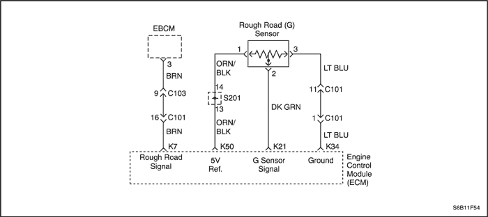
The Gravity Sensing Rough Road (G) sensor is a verticallow g-acceleration sensor. By sensing vertical accelerationcaused by bumps or potholes in the road, theEngine Control Module (ECM) can determine if thechanges in crankshaft speed are due to engine misfireor are driveline induced. If the G sensor detects a roughroad condition, the ECM misfire detection diagnostic willbe de-activated. The G sensor at rest output should bebetween 2.35-2.65 volts (+1G). During a rough roadcondition, the voltage output can vary between 0.5(-1G) and 4.5 volts (+3G).
Conditions for Setting the DTC
- Engine is running.
- Vehicle speed is less than or equal to 5 km/h (3.1mph).
- G sensor output at idle indicates below -0.39 volts orabove 2.21 volts.
OR
- Engine is running more than 10 seconds and vehiclespeed is between 30 mph (50 km/h) and 70 mph (112km/h).
- G sensor signal changes less than 0.00024 voltswhile driving.
Action Taken When the DTC Sets
- The Malfunction Indicator Lamp (MIL) will not illuminate.
- The ECM will record operating conditions at the timethe diagnostic fails. This information will be stored inthe Freeze Frame and Failure Records buffers.
- A history DTC is stored.
Conditions for Clearing the MIL/DTC
- A history Diagnostic Trouble Code (DTC) will clear after40 consecutive warm-up cycles without a fault.
- DTC(s) can be cleared by using the scan tool.
- Disconnecting the ECM battery feed for more than 10seconds.
Diagnostic Aids
Check for the following conditions:
- Poor connection at the ECM - Inspect the harnessconnections for backed-out terminals, improper mating,broken locks, improperly formed or damaged terminals,and poor terminal-to-wire connection.
- Damaged harness -- Inspect the wiring harness for damage. If the harness appears to be OK, observe the G sensor display on the scan tool while moving connectors and wiring harnesses related to the sensor. A change in the display will indicate the location of the fault.
Since the G sensor shares the ECM 5 volt reference and ground terminals with the A/C Pressure Sensor, a damaged A/C Pressure Sensor harness or sensor could cause a G sensor DTC to set. Refer to
"Multiple ECM Information Sensor DTCs Set" in this section.in this section.
The G sensor will give correct voltages only if it is level and mounted securely to its bracket.
Reviewing the Failure Records vehicle mileage since the diagnostic test last failed may help determine how often the condition that caused the DTC to be set occurs. This may assist in diagnosing the con
Test Description
The number(s) below refer to step(s) on the diagnostic table.
- The On-Board Diagnostic (EOBD) System Check prompts the technician to complete some basic checks and store the freeze frame and failure records data on the scan tool if applicable. This creates an electronic copy of the data taken when the malfunction occurred. The information is then stored on the scan tool for later reference.
DTC P1391 - Rough Road Sensor Performance
| Step | Action | Value(s) | Yes | No |
| 1 | Perform an On-Board Diagnostic (EOBD) System Check. Is the system check complete? | - | Go to Step 2 | |
| 2 | - Turn the ignition ON, with engine OFF.
- Install a scan tool to the Data Link Connector(DLC).
- Review and record the scan tool Failure Recordsdata.
- Operate the vehicle within Failure Records conditions as noted.
- Using the scan tool, monitor specific Diagnostic Trouble Code (DTC) info for DTC P1391.
Does the scan tool indicate that DTC P1391 failed? | - | Go to Step 4 | Go to Step 3 |
| 3 | Check for the following conditions and repair asneeded: - G sensor seal missing or damaged.
- G sensor mounting flanges cracked, missing, or incorrectly installed.
Is the repair complete? | - | Go to Step 14 | |
| 4 | - Turn the ignition OFF.
- Disconnect the G sensor electrical connector.
- Turn the ignition ON, with the engine OFF.
- Observe the G sensor value displayed on thescan tool.
Is the G sensor value near the specified value? | 0 v | Go to Step 5 | Go to Step 12 |
| 5 | - Jumper the 5 volt reference circuit, terminal 1 andthe G sensor signal circuit, terminal 2 together atthe G sensor harness connector.
- Observe the G sensor value displayed on the scan tool.
Is the G sensor value near the specified value? | 4.95 v | Go to Step 6 | Go to Step 7 |
| 6 | - Turn the ignition OFF.
- Disconnect the Engine Control Module (ECM) andcheck the sensor ground circuit for highresistance, an open between the ECM and the Gsensor, or for a poor connection at the terminalk34 of the ECM and repair as needed.
- f the problem is found, repair as necessary.
Is a problem found? | - | Go to Step 14 | Go to Step 10 |
| 7 | Check the 5 volt reference circuit for high resistance,an open between the ECM and the G sensor, or apoor connection at the terminal k50 of the ECM andrepair as needed. Is the repair complete? | - | Go to Step 14 | Go to Step 8 |
| 8 | - Turn the ignition OFF.
- Disconnect the ECM and check the G sensorsignal circuit for high resistance, an open, a shortto ground, or a short to the sensor ground circuitand repair as needed.
Is the repair complete? | - | Go to Step 14 | Go to Step 9 |
| 9 | Check the G sensor signal circuit for a poorconnection at the ECM and repair as needed. Is the repair complete? | - | Go to Step 14 | Go to Step 13 |
| 10 | Check for a poor connection at terminal 3 of the Gsensor and repair as needed. Is the repair complete? | - | Go to Step 14 | Go to Step 11 |
| 11 | Replace the G sensor. Is the repair complete? | - | Go to Step 14 | - |
| 12 | - Turn the ignition OFF.
- Disconnect the ECM.
- Turn the ignition ON.
- Check the G sensor signal circuit for a short tovoltage or a short to the 5 volt reference circuitand repair as needed.
Is the repair complete? | - | Go to Step 14 | Go to Step 13 |
| 13 | - Turn the ignition OFF.
- Replace the ECM.
Is the repair complete? | - | Go to Step 14 | - |
| 14 | - Using the scan tool, clear the DTCs.
- Start the engine and idle at normal operating temperature.
- Operate the vehicle within the conditions for setting this DTC as specified in the supporting text.
Does the scan tool indicate that this diagnostic ran and passed? | - | Go to Step 15 | Go to Step 2 |
| 15 | Check if any additional DTCs are set. Are any DTCs displayed that have not been diagnosed? | - | Go to Applicable DTC table | System OK |
 | |  | |
| © Copyright Chevrolet Europe. All rights reserved |