Diagnostic Trouble Code (DTC) P1392
Rough Road Sensor Circuit Low Voltage
Circuit Description
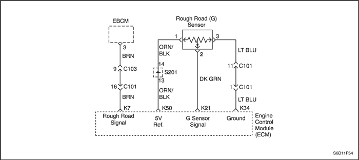
The Gravity Sensing Rough Road (G) sensor is a verticallow g-acceleration sensor. By sensing vertical accelerationcaused by bumps or potholes in the road, theEngine Control Module (ECM) can determine if thechanges in crankshaft speed are due to engine misfireor are driveline induced. If the G sensor detects a roughroad condition, the ECM misfire detection diagnostic willbe de-activated. The G sensor at rest output should bebetween 2.35-2.65 volts (+1G). During a rough roadcondition, the voltage output can vary between 0.5(-1G) and 4.5 volts (+3G).
Conditions for Setting the DTC
- G sensor output is less than 2%.
- Engine is running more than or equal to 10 seconds.
Action Taken When the DTC Sets
- The Malfunction Indicator Lamp (MIL) will not illuminate.
- The ECM will record operating conditions at the timethe diagnostic fails. This information will be stored inthe Freeze Frame and Failure Records buffers.
- A history DTC is stored.
Conditions for Clearing the MIL/DTC
- A history Diagnostic Trouble Code (DTC) will clear after40 consecutive warm-up cycles without a fault.
- DTC(s) can be cleared by using the scan tool.
- Disconnecting the ECM battery feed for more than 10seconds.
Diagnostic Aids
Check for the following conditions:
- Poor connection at the ECM - Inspect the harnessconnections for backed-out terminals, improper mating,broken locks, improperly formed or damaged terminals,and poor terminal-to-wire connection.
- Damaged harness - Inspect the wiring harness fordamage. If the harness appears to be OK, observethe G sensor display on the scan tool while movingconnectors and wiring harnesses related to the sensor.A change in the display will indicate the locationof the fault.
Since the G sensor shares the ECM 5 volt reference andground terminals with the A/C Pressure Sensor, a damagedA/C Pressure Sensor harness or sensor couldcause a G sensor DTC to set. Refer to
"Multiple ECM Information Sensor DTCs Set" in this section.
The G sensor will give correct voltages only if it is level and mounted securely to its bracket.
Reviewing the Failure Records vehicle mileage since the diagnostic test last failed may help determine how often the condition that caused the DTC to be set occurs. This may assist in diagnosing the condition.
Test Description
The number(s) below refer to step(s) on the diagnostic table.
- The On-Board Diagnostic (EOBD) System Check prompts the technician to complete some basic checks and store the freeze frame and failure records data on the scan tool if applicable. This creates an electronic copy of the data taken when the malfunction occurred. The information is then stored on the scan tool for later reference.
DTC P1392 - Rough Road Sensor Circuit Low Voltage
| Step | Action | Value(s) | Yes | No |
| 1 | Perform an On-Board Diagnostic (EOBD) System Check. Is the system check complete? | - | Go to Step 2 | |
| 2 | - Turn the ignition OFF.
- Install a scan tool to the Data Link Connector(DLC).
- Turn the ignition ON, with the engine OFF.
- Observe the ROUGH ROAD value displayed on the scan tool.
Is the ROUGH ROAD value near the specified value? | 0 v | Go to Step 4 | Go to Step 3 |
| 3 | - Review and record the scan tool Failure Records data.
- Operate the vehicle within Failure Recordsconditions as noted.
- Using the scan tool, monitor specific Diagnostic Trouble Code (DTC) info for DTC P1392.
Does the scan tool indicate that DTC P1392 failed? | - | Go to Step 4 | |
| 4 | - Turn the ignition OFF.
- Disconnect the G sensor electrical connector.
- Turn the ignition ON, with the engine OFF.
- Jumper the 5 volt reference circuit, terminal 1 andthe G sensor signal circuit, terminal 2 together atthe G sensor harness connector.
- Observe the G sensor value displayed on the scan tool.
Is the G sensor value near the specified value? | 4.95 v | Go to Step 9 | Go to Step 5 |
| 5 | - Turn the ignition OFF.
- Disconnect the Engine Control Module (ECM) andcheck the 5 volt reference circuit for an open orshort to ground and repair as needed.
Is the repair complete? | - | Go to Step 11 | Go to Step 6 |
| 6 | Check the 5 volt reference circuit for poorconnection at the ECM and repair or replace asneeded. Is the repair complete? | - | Go to Step 11 | Go to Step 7 |
| 7 | - Turn the ignition OFF.
- Disconnect the ECM and check the G sensorsignal circuit for an open, a short to ground, or ashort to the sensor ground circuit and repair asneeded.
Is the repair complete? | - | Go to Step 11 | Go to Step 8 |
| 8 | Check the G sensor signal circuit for a poorconnection at the ECM and repair as needed. Is the repair complete? | - | Go to Step 11 | Go to Step 10 |
| 9 | Replace the G sensor. Is the repair complete? | - | Go to Step 11 | - |
| 10 | - Turn the ignition OFF.
- Replace the ECM.
Is the repair complete? | - | Go to Step 11 | - |
| 11 | - Using the scan tool, clear the DTCs.
- Start the engine and idle at normal operating temperature.
- Operate the vehicle within the conditions for setting this DTC as specified in the supporting text.
Does the scan tool indicate that this diagnostic ran and passed? | - | Go to Step 12 | Go to Step 2 |
| 12 | Check if any additional DTCs are set. Are any DTCs displayed that have not been diagnosed? | - | Go to Applicable DTC table | System OK |
Diagnostic Trouble Code (DTC) P1393
Rough Road Sensor Circuit High Voltage
Circuit Description
The Rough Road (G) sensor is a vertical low g-accelerationsensor. By sensing vertical acceleration caused bybumps or potholes in the road, the Engine Control Module(ECM) can determine if the changes in crankshaftspeed are due to engine misfire or are driveline induced.If the G sensor detects a rough road condition, the ECMmisfire detection diagnostic will be de-activated. The Gsensor at rest output should be between 2.35-2.65 volts(+1G). During a rough road condition, the voltage outputcan vary between 0.5 (-1G) and 4.5 volts (+3G).
Conditions for Setting the DTC
- G sensor output is greater than 98%.
- Engine is running more than or equal to 10 seconds.
Action Taken When the DTC Sets
- The Malfunction Indicator Lamp (MIL) will not illuminate.
- The ECM will record operating conditions at the timethe diagnostic fails. This information will be stored inthe Freeze Frame and Failure Records buffers.
- A history DTC is stored.
Conditions for Clearing the MIL/DTC
- A history Diagnostic Trouble Code (DTC) will clear after40 consecutive warm-up cycles without a fault.
- DTC(s) can be cleared by using the scan tool.
- Disconnecting the ECM battery feed for more than 10seconds.
Diagnostic Aids
Check for the following conditions:
- Poor connection at the ECM - Inspect the harnessconnections for backed-out terminals, improper mating, broken locks, improperly formed or damaged terminals, and poor terminal-to-wire connection.
- Damaged harness - Inspect the wiring harness for damage. If the harness appears to be OK, observe the G sensor display on the scan tool while moving connectors and wiring harnesses related to the sensor. A change in the display will indicate the location of the fault.
Since the G sensor shares the ECM 5 volt reference and ground terminals with the A/C Pressure Sensor, a damaged A/C Pressure Sensor harness or sensor could cause a G sensor DTC to set. Refer to
"Multiple ECM Information Sensor DTCs Set" in this section.
The G sensor will give correct voltages only if it is level and mounted securely to its bracket.
Reviewing the Failure Records vehicle mileage since the diagnostic test last failed may help determine how often the condition that caused the DTC to be set occurs. This may assist in diagnosing the condition.
Test Description
The number(s) below refer to step(s) on the diagnostic table.
- The On-Board Diagnostic (EOBD) System Check prompts the technician to complete some basic checks and store the freeze frame and failure records data on the scan tool if applicable. This creates an electronic copy of the data taken when the malfunction occurred. The information is then stored on the scan tool for later reference.
DTC P1393 - Rough Road Sensor Circuit High Voltage
| Step | Action | Value(s) | Yes | No |
| 1 | Perform an On-Board Diagnostic (EOBD) System Check. Is the system check complete? | - | Go to Step 2 | |
| 2 | - Turn the ignition OFF.
- Install a scan tool to the Data Link Connector(DLC).
- Start and idle the engine.
- Observe the ROUGH ROAD value displayed on the scan tool.
Is the ROUGH ROAD value near the specified value? | 4.5 v | Go to Step 4 | Go to Step 3 |
| 3 | - Review and record the scan tool Failure Records data.
- Operate the vehicle within Failure Records conditions as noted.
- Using the scan tool, monitor specific Diagnostic Trouble Code (DTC) info for DTC P1393.
Does the scan tool indicate that DTC P1393 failed? | - | Go to Step 4 | |
| 4 | - Turn the ignition OFF.
- Disconnect the G sensor electrical connector.
- Turn the ignition ON, with the engine OFF.
- Note the G sensor voltage displayed on the scan tool.
Is the G sensor value near the specified value? | 0 v | Go to Step 5 | Go to Step 6 |
| 5 | Probe the sensor ground circuit terminal 3 with a test light to B+. Is the test light ON? | - | Go to Step 7 | Go to Step 9 |
| 6 | Check the G sensor signal circuit for a short tovoltage or a short to the 5 volt reference circuit andrepair as needed. Is the repair complete? | - | Go to Step 12 | Go to Step 11 |
| 7 | Check for a poor sensor ground terminal connection at the G sensor electrical connector. Is the repair complete? | - | Go to Step 12 | Go to Step 8 |
| 8 | Check for a poor sensor ground terminal connectionat the Engine Control Module (ECM) and repair asneeded. Is the repair complete? | - | Go to Step 12 | Go to Step 10 |
| 9 | Check the G sensor ground circuit for an open andrepair as needed. Is the repair complete? | - | Go to Step 12 | Go to Step 10 |
| 10 | - Turn the ignition OFF.
- Replace the ECM.
Is the repair complete? | - | Go to Step 12 | - |
| 11 | Replace the G sensor. Is the repair complete? | - | Go to Step 12 | Go to Step 10 |
| 12 | - Using the scan tool, clear the DTCs.
- Start the engine and idle at normal operating temperature.
- Operate the vehicle within the conditions for setting this DTC as specified in the supporting text.
Does the scan tool indicate that this diagnostic ran and passed? | - | Go to Step 13 | Go to Step 2 |
| 13 | Check if any additional DTCs are set. Are any DTCs displayed that have not been diagnosed? | - | Go to Applicable DTC table | System OK |
Diagnostic Trouble Code (DTC) P1396
ABS Wheel Speed Sensor (WSS) Signal Variation
Circuit Description
The engine control module (ECM) identifies engine misfire by detecting variations in crankshaft speed. Crankshaft speed variations can also occur when a vehicle is operated over a rough road. The Anti-Lock Brake System (ABS) can detect if the vehicle is on a rough surface based on wheel acceleration/deceleration data supplied by each wheel speed sensor. This information is sent to the ECM by the Electronic Brake Control Module (EBCM) through the Instrument Panel Cluster (IPC) over the Universal Asynchronous Receiver Transmitter (UART) serial data line. The ECM then uses this information to determine if the crankshaft variations are being caused by an actual engine misfire or from being driven on a rough surface.
If the ABS is found to be malfunctioning, the ECM will still continue to detect for misfire. However, if a misfire Diagnostic Trouble Code (DTC) is set, this additional DTC will also be set, indicating that rough surface data was not usable during the misfire detection due to the ABS malfunction.
Conditions for Setting the DTC
- WSS PWM signal is between 95% and 98%.
- ABS system has detected a wheel speed sensor fault.
- Engine running is greater than or equal to 10 seconds.
Action Taken When the DTC Sets
- The Malfunction Indicator Lamp (MIL) will not illuminate.
- The ECM will record operating conditions at the time the diagnostic fails. This information will be stored in the Failure Records buffers.
- A history DTC is stored.
Conditions for Clearing the MIL/DTC
- A history DTC will clear after 40 consecutive warm-up cycles without a fault.
- DTCs can be cleared by using a scan tool.
Diagnostic Aids
The setting of this DTC indicates that a misfire was detected and that the ECM could not determine if the detected misfire was true or due to operating the vehicle on a rough surface. A misfire can be a true misfire with or without setting this DTC. Check the IPC and the EBCM for poor connections at the UART serial data terminals. Be sure no true misfire exists after repairing the cause of this DTC.
Test Description
The number(s) below refer to step(s) on the diagnostic table.
- The On-Board Diagnostic (EOBD) System Check prompts the technician to complete some basic checks and store the freeze frame and failure records data on the scan tool if applicable. This creates an electronic copy of the data taken when the malfunction occurred. The information is then stored on the scan tool for later reference.
- Be careful to clear only DTCs and not the captured information stored on the scan tool. The scan tool will issue a warning if this is about to happen.
- A DTC P1396 being reset indicates that the ECM is not receiving the correct information from the EBCM due to an ABS DTC.
- When DTC P1396 is set, an ABS DTC should also be set.
- Repair any condition that remains and is causing a misfire by following the table for any DTC that has set.
- The replacement ECM must be reprogrammed. Refer to the latest Techline procedure for ECM reprogramming.
DTC P1396 - ABS Wheel Speed Sensor (WSS) Signal Variation
| Step | Action | Value(s) | Yes | No |
| 1 | Perform an On-Board Diagnostic (EOBD) System Check. Is the system check complete? | - | Go to Step 2 | |
| 2 | - Turn the ignition ON with engine OFF.
- Install the scan tool.
- Check for any ABS Diagnostic Trouble Codes (DTCs).
Are any ABS DTCs set? | - | Go to applicable DTC table | Go to Step 3 |
| 3 | - Review the Freeze Frame data and note the parameters.
- Operate the vehicle within the Freeze Frame conditions and Conditions for Setting the DTC as noted when driving on a rough surface.
Does the misfire set? | - | Go to Step 4 | Go to Step 8 |
| 4 | Check the scan tool. Does DTC P1396 set? | - | Go to Step 5 | Go to Step 6 |
| 5 | Check the scan tool. Does an ABS DTC set? | - | Go to Step 5 | Go to Step 6 |
| 6 | Repair the condition causing the misfire. Is the repair complete? | - | Go to Step 8 | - |
| 7 | - Turn the ignition OFF.
- Replace the engine control module (ECM).
Is the repair complete? | - | Go to Step 8 | - |
| 8 | - Using the scan tool, clear the DTCs.
- Start the engine and idle at normal operating temperature.
- Operate the vehicle within the conditions for setting this DTC as specified in the supporting text.
Does the scan tool indicate that this diagnostic ran and passed? | - | Go to Step 9 | Go to Step 2 |
| 9 | Check if any additional DTCs are set. Are any DTCs displayed that have not been diagnosed? | - | Go to Applicable DTC table | System OK |
Diagnostic Trouble Code (DTC) P1397
ABS Wheel Speed Sensor (WSS) No Signal
Circuit Description
The engine control module (ECM) identifies engine misfire by detecting variations in crankshaft speed. Crankshaft speed variations can also occur when a vehicle is operated over a rough road. The Anti-Lock Brake System (ABS) can detect if the vehicle is on a rough surface based on wheel acceleration/deceleration data supplied by each wheel speed sensor. This information is sent to the ECM by the Electronic Brake Control Module EBCM through the Instrument Panel Cluster (IPC) over the Universal Asynchronous Receiver Transmitter (UART) serial data line. The ECM then uses this information to determine if the crankshaft variations are being caused by an actual engine misfire or from being driven on a rough surface.
If the ABS is found to be malfunctioning, the ECM will still continue to detect for misfire. However, if a misfire Diagnostic Trouble Code (DTC) is set, this additional DTC will also be set, indicating that rough surface data was not usable during the misfire detection due to the ABS malfunction.
Conditions for Setting the DTC
- WSS PWM signal is less than 5% ir greater than 98%.
- Engine running is greater than or equal to 10 seconds.
Action Taken When the DTC Sets
- The Malfunction Indicator Lamp (MIL) will not illuminate.
- The ECM will record operating conditions at the time the diagnostic fails. This information will be stored in the Failure Records buffers.
- A history DTC is stored.
Conditions for Clearing the MIL/DTC
- A history DTC will clear after 40 consecutive warm-up cycles without a fault.
- DTCs can be cleared by using a scan tool.
Diagnostic Aids
The setting of this DTC indicates that a misfire was detected and that the ECM could not determine if the detected misfire was true or due to operating the vehicle on a rough surface. A misfire can be a true misfire with or without setting this DTC. Check the IPC and the EBCM for poor connections at the UART serial data terminals. Be sure no true misfire exists after repairing the cause of this DTC.
Test Description
The number(s) below refer to step(s) on the diagnostic table.
- The On-Board Diagnostic (EOBD) System Check prompts the technician to complete some basic checks and store the freeze frame and failure records data on the scan tool if applicable. This creates an electronic copy of the data taken when the malfunction occurred. The information is then stored on the scan tool for later reference.
- Be careful to clear only DTCs and not the captured information stored on the scan tool. The scan tool will issue a warning if this is about to happen.
- A DTC P1397 being reset indicates that the ECM is not receiving the correct information from the EBCM due to an ABS DTC.
- When DTC P1397 is set, an ABS DTC should also be set.
- Repair any condition that remains and is causing a misfire by following the table for any DTC that has set.
- The replacement ECM must be reprogrammed. Refer to the latest Techline procedure for ECM reprogramming.
DTC P1397 - ABS Wheel Speed Sensor (WSS) No Signal
| Step | Action | Value(s) | Yes | No |
| 1 | Perform an On-Board Diagnostic (EOBD) System Check. Is the system check complete? | - | Go to Step 2 | |
| 2 | - Turn the ignition ON with engine OFF.
- Install the scan tool.
- Check for any ABS Diagnostic Trouble Codes (DTCs).
Are any ABS DTCs set? | - | Go to applicable DTC table | Go to Step 3 |
| 3 | - Review the Freeze Frame data and note the parameters.
- Operate the vehicle within the Freeze Frame conditions and Conditions for Setting the DTC as noted when driving on a rough surface.
Does the misfire set? | - | Go to Step 4 | Go to Step 8 |
| 4 | Check the scan tool. Does DTC P1397 set? | - | Go to Step 5 | Go to Step 6 |
| 5 | Check the scan tool. Does an ABS DTC set? | - | Go to Step 5 | Go to Step 6 |
| 6 | Repair the condition causing the misfire. Is the repair complete? | - | Go to Step 8 | - |
| 7 | - Turn the ignition OFF.
- Replace the engine control module (ECM).
Is the repair complete? | - | Go to Step 8 | - |
| 8 | - Using the scan tool, clear the DTCs.
- Start the engine and idle at normal operating temperature.
- Operate the vehicle within the conditions for setting this DTC as specified in the supporting text.
Does the scan tool indicate that this diagnostic ran and passed? | - | Go to Step 9 | Go to Step 2 |
| 9 | Check if any additional DTCs are set. Are any DTCs displayed that have not been diagnosed? | - | Go to Applicable DTC table | System OK |
Diagnostic Trouble Code (DTC) P1631
Theft Deterrent Fuel Enable Signal Not Correct
Circuit Description
The Engine Control Module (ECM) is the control center of the fuel injection system. It constantly looks at the information from various sensors, and controls the systems that affect vehicle performance. The ECM also performs the diagnostic function of the system. It can recognize operational problems, alert the driver through the Malfunction Indicator Lamp (MIL) (Check Engine), and store a Diagnostic Trouble Code (DTC) or DTCs which identify the problem areas to aid the technician in making repairs. The ECM received incorrect message identification.
Conditions for Setting the DTC
- Wrong immobilizer message received.
- Ignition switch is turned to ON.
- Immobilizer option selected.
- ECM release time window expired.
- Vehicle Speed Sensor (VSS) is less than 512 km/h.
Action Taken When the DTC Sets
- The Malfunction Indicator Lamp (MIL) will not illuminate.
- The ECM will record operating conditions at the time the diagnostic fails. This information will be stored in the Failure Records buffers.
- A history DTC is stored.
Conditions for Clearing the MIL/DTC
- A history DTC will clear after 40 consecutive warm-up cycles without a fault.
- DTC(s) can be cleared by using the scan tool.
- Disconnecting the ECM battery feed for more than 10 seconds.
DTC P1631 - Theft Deterrent Fuel Enable Signal Not Correct
| Step | Action | Value(s) | Yes | No |
| 1 | Perform an On-Board Diagnostic (EOBD) System Check. Was the check performed? | - | Go to Step 2 | |
| 2 | - Turn the ignition OFF.
- Replace the Engine Control Module (ECM).
Is the repair complete? | - | Go to Step 3 | - |
| 3 | - Using the scan tool, clear the Diagnostic TroubleCodes (DTCs).
- Start the engine and idle at normal operatingtemperature.
- Operate the vehicle within the Conditions forsetting this DTC as specified in the supportingtext.
Does the scan tool indicate that this diagnostic hasrun and passed? | - | Go to Step 4 | Go to Step 2 |
| 4 | Check if any additional DTCs are set. Are any DTCs displayed that have not beendiagnosed? | - | Go to Applicable DTC table | System OK |
Diagnostic Trouble Code (DTC) P2297
HO2S Performance During Decel Fuel Cut-Off (DFCO) Sensor 1
Circuit Description
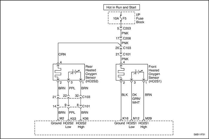
The Engine Control Module (ECM) supplies a voltage of about 0.45 volts between terminals M12 and M29 (if measured with a 10 megohm digital voltmeter, this may read as low as 0.32 volts). The Front Heated Oxygen Sensor (HO2S1) varies the voltage within a range of about 1 volt if the exhaust is rich, down through about 0.10 volts if the exhaust is lean.
In internal circuitry of the Engine control Module (ECM) can identify if the vehicle fuel system is capable of cutoff amount of the fuel supply during deceleration. When a Decel Fuel Cutoff (DFCO) mode of operation is requested during Closed Loop operation, the ECM will cutoff the fuel supply to the engine. Under these conditions the ECM should detect a lean condition. If the ECM detect a rich condition at this time, Diagnostic Trouble Code (DTC) P1167 will set. Damaged fuel pressure regulator and faulty injector will be the cause of this DTC.
Conditions for Setting the DTC
- HO2S1 voltage is greater than 0.55 volts in Decel Fuel Cutoff (DFCO) mode.
- System voltage is greater than 10 volts.
- DTCs P0106, P0107, P0108, P0117, P0118, P0122, P0123, P0171, P0172, P0201, P0202, P0203, P0204, P0300, P0336, P0351, P0352, P0402, P0404, P0405, P0406, P0506, P0507 and P0443 are not set.
- 3 second delay after in DFCO mode.
Action Taken When the DTC Sets
- The Malfunction Indicator Lamp (MIL) will illuminate.
- The ECM will record operating conditions at the time the diagnostic fails. This information will be stored in the Freeze Frame and Failure Records buffers.
- A history DTC is stored.
- The vehicle will operate in Open Loop.
Conditions for Clearing the MIL/DTC
- The MIL will turn off after four consecutive ignition cycles in which the diagnostic runs without a fault.
- A history DTC will clear after 40 consecutive warm-up cycles without a fault.
- DTC can be cleared by using the scan tool.
- Disconnecting the ECM battery feed for more than 10 seconds.
Diagnostic Aids
The DTC P2297 or rich exhaust is most likely caused by one of the following items:
- Leaking injector - A leaking or malfunctioning injector can cause the system to go rich causing a DTC P0132.
- Pressure regulator - Check for a leaking fuel pressure regulator diaphragm by checking for the presence of liquid fuel in the vacuum line to the regulator.
DTC P2297 - HO2S Performance During Decel Fuel Cut-Off (DFCO) Sensor 1
| Step | Action | Value(s) | Yes | No |
| 1 | Perform an On-Board Diagnostic (EOBD) System Check. Was the check performed? | - | Go to Step 2 | |
| 2 | - Install a scan tool to the Data Link Connector (DLC).
- Turn the ignition ON.
Any other component related Diagnostic Trouble Codes (DTCs) set? | - | Go to applicable DTC table | Go to Step 3 |
| 3 | - Using a scan tool, observe the Front Heated Oxygen Sensor (HO2S1) voltage while decelerating the engine.
- The HO2S1 voltage should vary from specified voltage (100-900 mV) and while decelerating occasionally toggle below the specified voltage.
Is the HO2S1 voltage toggle? | 550 mV | Go to Step 4 | |
| 4 | Is the repair complete? | - | Go to Step 6 | Go to Step 5 |
| 5 | - Turn the ignition OFF.
- Replace the Engine Control Module (ECM).
Is the repair complete? | - | Go to Step 6 | - |
| 6 | - Using the scan tool, clear the Diagnostic Trouble Codes (DTCs).
- Start the engine and idle at normal operating temperature.
- Operate the vehicle within the Conditions for setting this DTC as specified in the supporting text.
Does the scan tool indicate that this diagnostic has run and passed? | - | Go to Step 7 | Go to Step 2 |
| 7 | Check if any additional DTCs are set. Are any DTCs displayed that have not been diagnosed? | - | Go to Applicable DTC table | System OK |
Diagnostic Trouble Code (DTC) P2610
Control Module Ignition Off Timer Performance
Circuit Description
The Engine Control Module (ECM) is the control centerof the fuel injection system. It constantly looks at the informationfrom various sensors, and controls the systemsthat affect vehicle performance. The ECM alsoperforms the diagnostic function of the system. It canrecognize operational problems, alert the driver throughthe Malfunction Indicator Lamp (MIL) (Check Engine),and store a Diagnostic Trouble Code (DTC) or DTCswhich identify the problem areas to aid the technician inmaking repairs. An Electrically Erasable ProgrammableRead Only Memory (EEPROM) is used to house theprogram information and the calibrations required forengine, transmission, and powertrain diagnostics operation. The ECM checks operation of Lower Power Counter Integrated Chip (I/C) and communication between main CPU and Lower Power Counter I/C. The ECM also monitors EEPROM reset flag and Lower Power Counter I/C overflow bits. If the ECM detects ifLower Power Counter I/C has been reset due to batterydisconnect or Lower Power Counter I/C malfunction, theDiagnostic Trouble Code (DTC) will stored.
Conditions for Setting the DTC
(Lower Power Counter Error)
- Ignition switch is turned to ON.
- Ignition voltage is greater than 11V.
- Engine is running more than 10 seconds.
(Lower Power Counter Reset)
- Ignition switch is turned to ON.
- Engine is not running.
Action Taken When the DTC Sets
- The Malfunction Indicator Lamp (MIL) will illuminate.
- The ECM will record operating conditions at the timethe diagnostic fails. This information will be stored inthe Freeze Frame and Failure Records buffers.
- A history DTC is stored.
Conditions for Clearing the MIL/DTC
- A history DTC will clear after 40 consecutive warm-up cycles without a fault.
- DTC(s) can be cleared by using the scan tool.
- Disconnecting the ECM battery feed for more than 10seconds.
DTC P2610 - Control Module Ignition Off Timer Performance
| Step | Action | Value(s) | Yes | No |
| 1 | Perform an On-Board Diagnostic (EOBD) System Check. Was the check performed? | - | Go to Step 2 | |
| 2 | - Using the scan tool, clear the Diagnostic TroubleCodes (DTCs).
- Start the engine and idle at normal operatingtemperature.
- Operate the vehicle within the Conditions forsetting this DTC as specified in the supportingtext.
Does the scan tool indicate that this diagnostic hasrun and passed? | - | Go to Step 5 | Go to Step 3 |
| 3 | - Turn the ignition OFF.
- Replace the Engine Control Module (ECM).
Is the repair complete? | - | Go to Step 4 | - |
| 4 | - Using the scan tool, clear the Diagnostic TroubleCodes (DTCs).
- Start the engine and idle at normal operatingtemperature.
- Operate the vehicle within the Conditions forsetting this DTC as specified in the supportingtext.
Does the scan tool indicate that this diagnostic hasrun and passed? | - | Go to Step 5 | Go to Step 2 |
| 5 | Check if any additional DTCs are set. Are any DTCs displayed that have not beendiagnosed? | - | Go to Applicable DTC table | System OK |
Diagnostic Trouble Code (DTC) U0101
Lost Communication With TCM
Circuit Description
The Serial Peripheral Interface (SPI) communication is used internally by the Engine Control Module (ECM) to send message between the engine processor and the automatic transaxle processor. Included in each message sent between the two processor is a checksum of the message. Both the engine processor automatic transaxle processor will compare this checksum value with calculated checksum. If the checksum do not match, the processor will review the new data as being corrupted and ignore the value. The processor then use the previous message. The receiving processor will then send a message to the sending processor informing it that its last message was corrupted.
The ECM monitor periodic TCM status message and if message is not received fail counter incremented and Diagnostic trouble Code (DTC) will stored.
Conditions for Setting the DTC
- Ignition switch is turned to ON.
- Ignition voltage is greater than 11 volts.
- Engine is running more than 2 seconds.
- Device Control not active.
Action Taken When the DTC Sets
- The Malfunction Indicator Lamp (MIL) will illuminate.
- The ECM will record operating conditions at the time the diagnostic fails. This information will be stored in the Freeze Frame and Failure Records buffers.
- A history DTC is stored.
Conditions for Clearing the MIL/DTC
- The MIL turn off after four consecutive ignition cycles in which the diagnostic runs without a fault.
- A history DTC will clear after 40 consecutive warm-up cycles without a fault.
- DTC(s) can be cleared by using the scan tool.
- Disconnecting the ECM battery feed for more than 10 seconds.
DTC U0101 - Lost Communication With TCM
| Step | Action | Value(s) | Yes | No |
| 1 | Perform an On-Board Diagnostic (EOBD) System Check. Was the check performed? | - | Go to Step 2 | |
| 2 | - Turn the ignition OFF.
- Replace the Engine Control Module (ECM).
Is the repair complete? | - | Go to Step 3 | - |
| 3 | - Using the scan tool, clear the Diagnostic TroubleCodes (DTCs).
- Start the engine and idle at normal operatingtemperature.
- Operate the vehicle within the Conditions forsetting this DTC as specified in the supportingtext.
Does the scan tool indicate that this diagnostic hasrun and passed? | - | Go to Step 4 | Go to Step 2 |
| 4 | Check if any additional DTCs are set. Are any DTCs displayed that have not beendiagnosed? | - | Go to Applicable DTC table | System OK |
Diagnostic Trouble Code (DTC) U0167
No Immobilizer Message ID
Circuit Description
The Engine Control Module (ECM) is the control center of the fuel injection system. It constantly looks at the information from various sensors, and controls the systems that affect vehicle performance. The ECM also performs the diagnostic function of the system. It can recognize operational problems, alert the driver through the Malfunction Indicator Lamp (MIL) (Check Engine), and store a Diagnostic Trouble Code (DTC) or DTCs which identify the problem areas to aid the technician in making repairs. The ECM detects communication link failure with immobilizer control unit.
Conditions for Setting the DTC
- No immobilizer message identification for ECM release time window (1.0 or 1.5 seconds).
- Ignition switch is turned to ON.
- Vehicle Speed Sensor (VSS) is less than 512 km/h.
Action Taken When the DTC Sets
- The Malfunction Indicator Lamp (MIL) will not illuminate.
- The ECM will record operating conditions at the time the diagnostic fails. This information will be stored in the Failure Records buffers.
- A history DTC is stored.
Conditions for Clearing the MIL/DTC
- A history DTC will clear after 40 consecutive warm-up cycles without a fault.
- DTC(s) can be cleared by using the scan tool.
- Disconnecting the ECM battery feed for more than 10 seconds.
DTC U0167 - No Immobilizer Message ID
| Step | Action | Value(s) | Yes | No |
| 1 | Perform an On-Board Diagnostic (EOBD) System Check. Was the check performed? | - | Go to Step 2 | |
| 2 | - Turn the ignition OFF.
- Replace the Engine Control Module (ECM).
Is the repair complete? | - | Go to Step 3 | - |
| 3 | - Using the scan tool, clear the Diagnostic TroubleCodes (DTCs).
- Start the engine and idle at normal operatingtemperature.
- Operate the vehicle within the Conditions forsetting this DTC as specified in the supportingtext.
Does the scan tool indicate that this diagnostic hasrun and passed? | - | Go to Step 4 | Go to Step 2 |
| 4 | Check if any additional DTCs are set. Are any DTCs displayed that have not beendiagnosed? | - | Go to Applicable DTC table | System OK |
| © Copyright Chevrolet Europe. All rights reserved |