UNIT REPAIR


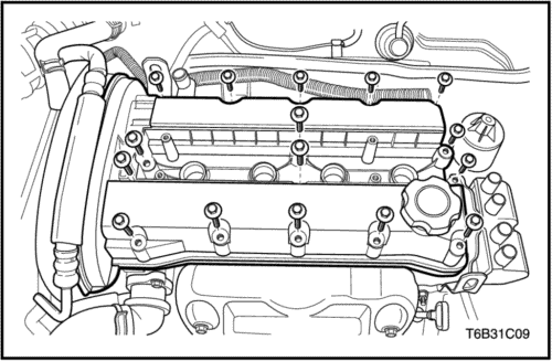
Cylinder Head and Valve Train Components
Tools Required
MKM-571-B Gauge
KM-340-0 Cutter Set
KM-340-7 Guide Drift
KM-340-13 Cutters
KM-340-26 Cutters
KM-348 Valve Spring Compressor
KM-653 Adapter
KM-805 Valve Guide Reamer
Disassembly Procedure
- Remove the cylinder head with the intake manifold and the exhaust manifold attached. Refer to "Cylinder Head and Gasket" in this section.
- Remove the engine coolant temperature (ECT) sensor.
- Remove the exhaust manifold heat shield bolts.
- Remove the exhaust manifold heat shield.
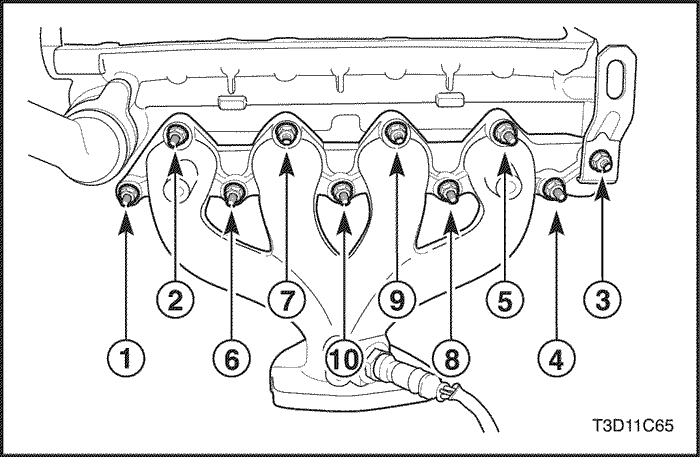
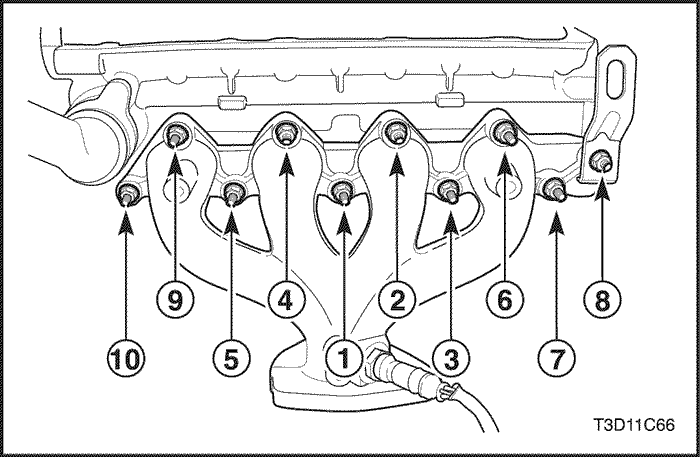
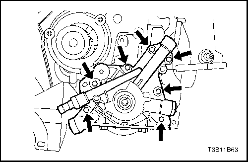
- Remove the exhaust manifold retaining nuts in the sequence shown.
- Remove the exhaust manifold.
- Remove the exhaust manifold gasket.
- Remove the exhaust manifold studs.
- Remove the thermostat housing mounting bolts.
- Remove the thermostat housing assembly.
- Remove the fuel rail retaining bolts and the fuel rail assembly.
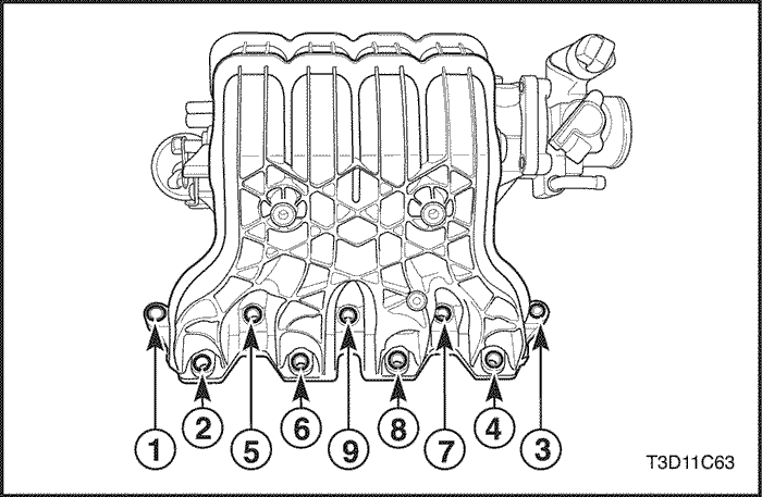
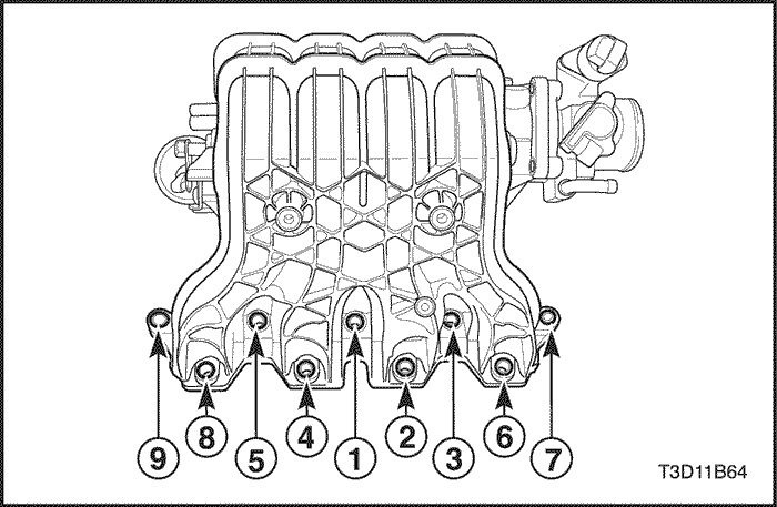
- Remove the intake manifold retaining nuts and retaining bolts in the sequence shown.
- Remove the intake manifold.
- Remove the intake manifold gasket.
- Remove the intake manifold studs.
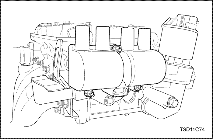
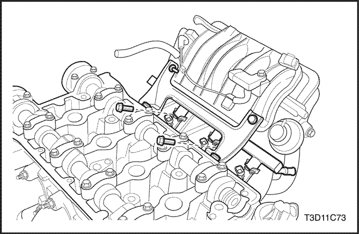
- Remove the electronic ignition (EI) system ignition coil mounting bolts.
- Remove the EI system ignition coil with the ignition wires attached.
- Remove the EI system ignition coil mounting bracket bolts.
- Remove the EI system ignition coil mounting bracket.
- Remove the exhaust gas recirculation (EGR) valve adapter bolts.
- Remove the EGR valve adapter.
- Remove the EGR valve adapter gasket.
- Remove the spark plugs.
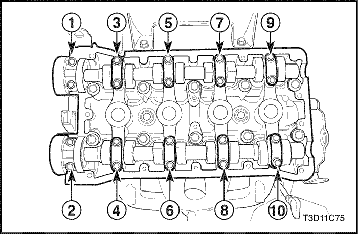
- Remove the camshaft cap bolts and in the sequence shown.
- Remove the intake camshaft caps. Maintain the correct positions for installation.
- Remove the intake camshaft.
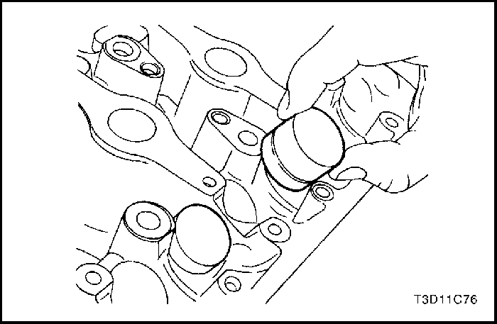
- Remove the intake valve lash adjusters.
- Remove the exhaust camshaft caps. Maintain the correct positions for installation.
- Remove the exhaust camshaft.
- Remove the exhaust valve lash adjusters.
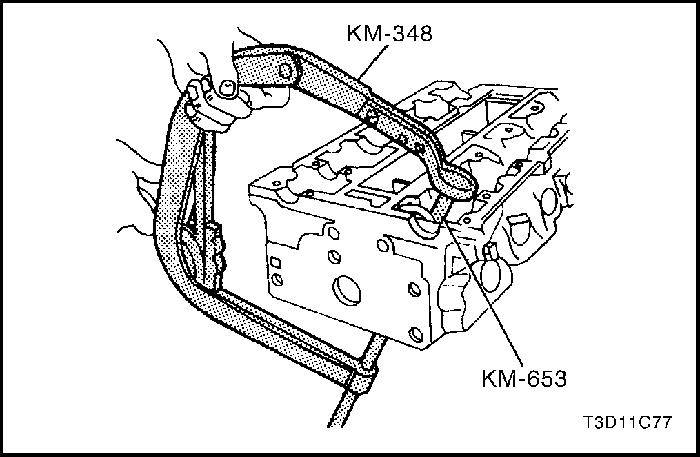
- Compress the valve springs with the valve spring compressor KM-348 and the adapter KM-653.
- Remove the valve retainers.
- Remove the valve spring compressor KM-348 and the adapter KM-653.
- Remove the valve spring caps.
- Remove the valve springs. Maintain the original position of the valves springs for installation.
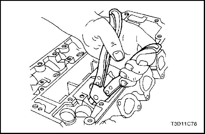
- Remove the valves. Maintain the original position of the valves for installation.
- Remove the valve stem seals.
Cylinder Head Inspection
- Clean the sealing surfaces.
- Inspect the cylinder head gasket and mating surfaces for leaks, corrosion and blowby.
- Inspect the cylinder head for cracks.
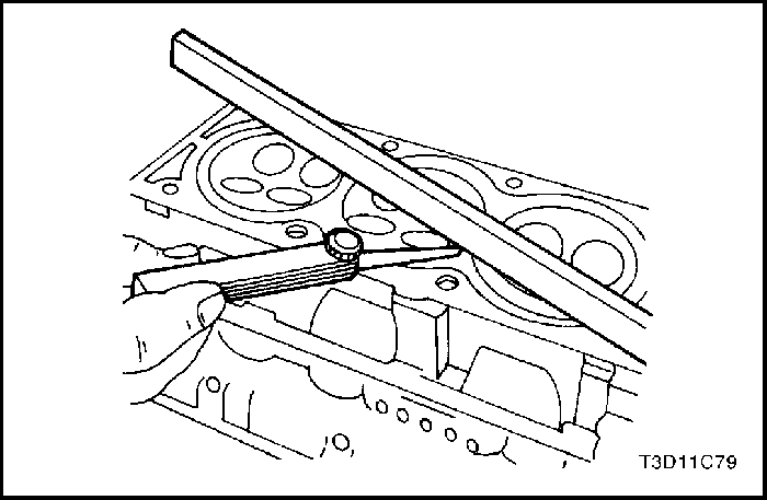
- Inspect the length and width of the cylinder head using a feeler gauge and a straight edge.
- Check the sealing surfaces for deformation and warpage. The cylinder head sealing surfaces must be flat within 0.050 mm (0.002 inch) maximum.
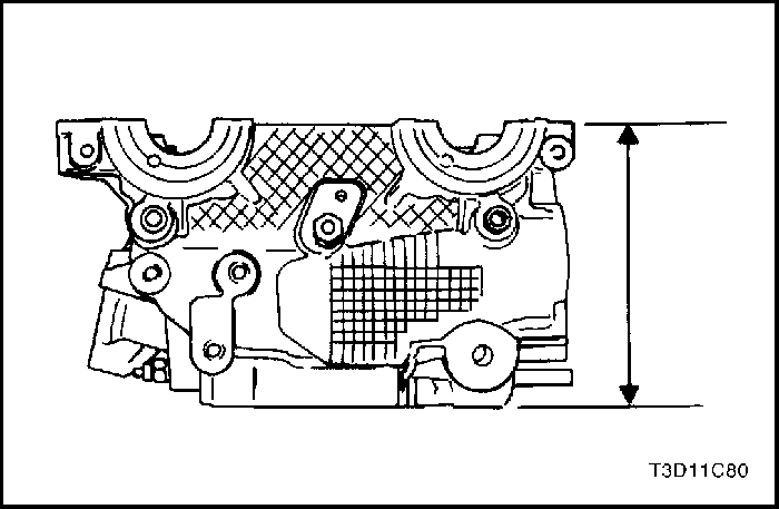
- Measure the height of the cylinder head from sealing surface to sealing surface. The cylinder head height should be 134.08 to 134.23mm (5.279 to 5.285 inches). If the cylinder head height is less than 134.08 mm (5.279 inches), replace the cylinder head.
- Inspect all threaded holes for damage.
- Inspect all valve seats for excessive wear and burned spots.
Valve Inspection
- Inspect the valve stem tip for wear.
- Inspect the valve retainer grooves and the oil seal grooves for chips and wear.
- Inspect the valves for burns or cracks.
- Inspect the valve stem for burrs and scratches.
- Inspect the valve stem. The valve stem must be straight.
- Inspect the valve face for grooving. If the groove is so deep that refacing the valve would result in a sharp edge, replace the valve.
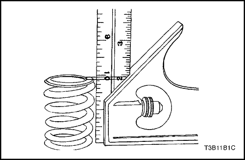
- Inspect the valve spring. If the valve spring ends are not parallel, replace the valve spring.
- Measure the valve spring height. Refer to "Engine Specifications" in this section. If the valve spring height does not match the specifications, replace the valve spring.
- Inspect the valve spring seating surface of the valve rotators for wear or gouges. Replace as required.
Cleaning Procedure
- Clean the cylinder head.
- Clean the valve guides.
- Clean all of the threaded holes.
- Clean all carbon, oil, and varnish from the valves.
Cylinder Head Overhaul
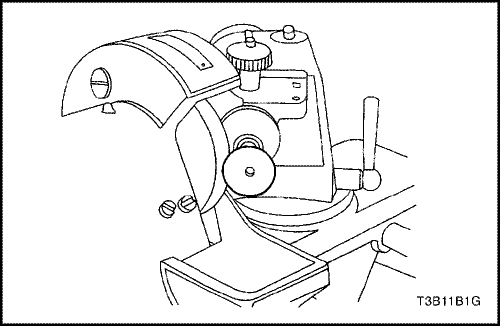
Valve Grind-in
- Lubricate the valve stem using a fine-grained paste.
- Lift the valve rhythmically from the seat with a commercially available valve grinding tool in order to distribute the paste.
- Check the contact pattern on the valve head and in the cylinder head.
- Clean the valves, the valve guides, and the cylinder head.
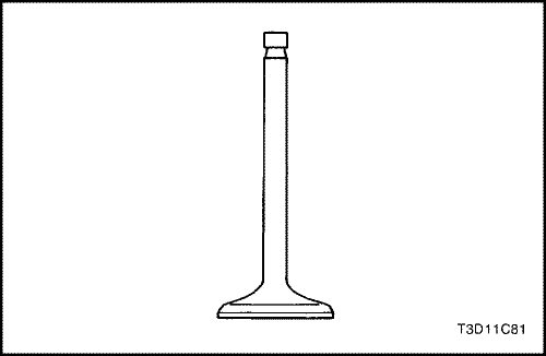
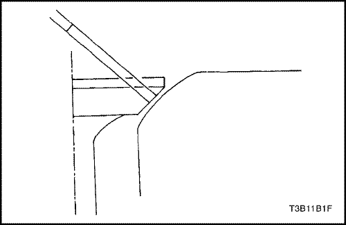
Valve Grind
- Make sure there are no crater line burns on the valve cone.
- The valve may be reground only two times. Do not grind the valve stem end.
- The angle at the valve face is 45 degrees.
- Inspect the assembly height of the intake valves and the exhaust valves.
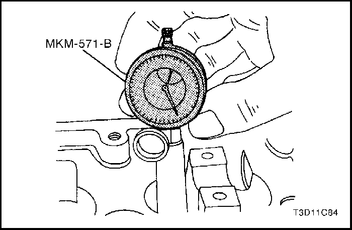
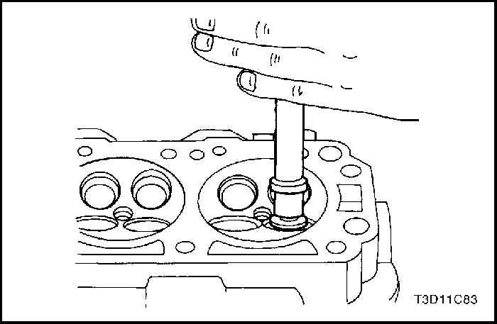
Valve Guide - Ream
- Measure the diameter of the valve guide using gauge MKM-571-B and a commercially available inside micrometer.
Important : Valve oversizes may already have been fitted in production.
- An oversize service code is on the valve guide and the valve stem end. The following table gives the correct size, reamer, and production code for each service.
Size | Reamer | Production Code | Service Code |
Normal | - | - | K |
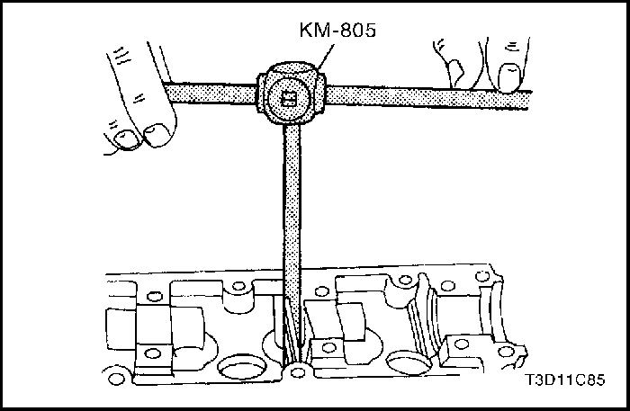
0.075 | KM-805 | 1 | K1 |
0.150 | . | 2 | K2 |
- Ream the valve guide from the upper side of the cylinder head to the next oversize.
- After reaming, cross out the code and emboss the valve guide with the new code.
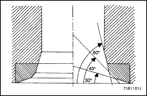
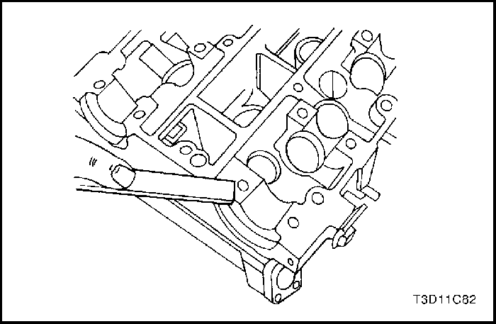
Valve Seat - Cut
- Place the cylinder head on wooden blocks.
- Cut the intake and the exhaust valve seats using the guide drift KM-340-7 as follows:
- Valve seat: A 45-degree side using the cutter KM-340-13.
- Upper correction angle: A 30-degree side using the cutter KM-340-13.
- Lower Correction Angle: A 60-degree side using cutter KM-340-26.
- Clean the chippings from the cylinder head.
- Inspect the dimension to make sure the valve seat width is as follows.
- Intake: 1.17 to 1.57 mm (0.046 to 0.062 inch).
- Exhaust: 1.07 to 1.47 mm (0.042 to 0.058 inch).
- Inspect the assembly height of the intake valves and the exhaust valves.
- If the dimension is exceeded, install new valves.
- Inspect the assembly height of the intake valves and the exhaust valves again.
- If the valve assembly height is still too large despite replacing the valves, replace the cylinder head.
Assembly Procedure
- Install the valve stem seals.
- Lubricate the valve stems with engine oil.
- Carefully install the valves in their original positions. Do not damage the valve stem seals.
- Install the valve springs in their original positions.
- Install the valve spring caps.
- Compress the valve springs with the valve spring compressor KM-348 and adapter KM-653.
- Install the valve retainers.
- Remove the valve spring compressor KM-348 and adapter KM-653.
- Lubricate the valve lash adjusters with engine oil.
- Install the valve lash adjusters.
- Install the intake camshaft.
- Install the intake camshaft caps in their original positions.
- Install the exhaust camshaft.
- Install the exhaust camshaft caps in their original positions.
- Install the camshaft cap bolts.
- Tighten the camshaft cap bolts gradually and in the sequence shown for each camshaft cap.
Tighten
Tighten the camshaft cap bolts to 16 N•m (12 lb-ft).
- Install the spark plugs.
Tighten
Tighten the spark plugs to 25 N•m (18 lb-ft).
- Install the exhaust gas recirculation (EGR) valve adapter gasket.
- Install the EGR valve adapter.
- Install the EGR valve adapter bolts.
Tighten
Tighten the exhaust gas recirculation valve adapter bolts to 25 N•m (18 lb-ft).
- Install the EI system ignition coil mounting bracket.
- Install the EI system ignition coil mounting bracket bolts.
Tighten
Tighten the electronic ignition system ignition coil mounting bracket bolts to 10 N•m (89 lb-in).
- Install the EI ignition coil with the ignition wires attached.
- Install the EI ignition coil mounting bolts.
Tighten
Tighten the electronic ignition system ignition coil mounting bolts to 10 N•m (89 lb-in).
- Install the intake manifold studs.
- Install the intake manifold gasket.
- Install the intake manifold.
- Install the intake manifold retaining nuts and retaining bolts in the sequence shown.
Tighten
Tighten the intake manifold retaining nuts/bolts to 25 N•m (18 lb-ft).
- Install the fuel rail assembly with the bolts.
Tighten
Tighten the fuel rail retaining bolts to 25 N•m (18 lb-ft).
- Install the thermostat housing assembly.
- Install the thermostat housing mounting bolts.
Tighten
Tighten the thermostat housing mounting bolts to 20 N•m (15 lb-ft).
- Install the exhaust manifold studs.
- Install the exhaust manifold gasket.
- Install the exhaust manifold.
- Install the exhaust manifold retaining nuts in the sequence shown.
Tighten
Tighten the exhaust manifold retaining nuts to 25 N•m (18 lb-ft).
- Install the exhaust manifold heat shield.
- Install the exhaust manifold heat shield bolts.
Tighten
Tighten the exhaust manifold heat shield bolts to 15 N•m (11 lb-ft).
- Install the ECT.
Tighten
Tighten the engine coolant temperature sensor to 20 N•m (15 lb-ft).
- Install the cylinder head with the intake manifold and the exhaust manifold attached. Refer to "Cylinder Head and Gasket" in this section.
Crankshaft
Tools Required
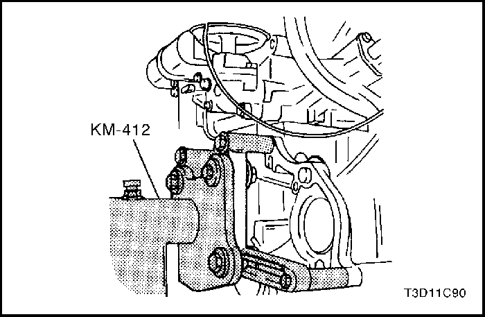
KM-412 Engine Overhaul Stand
J-42492 Timing Belt Adjuster
KM-470-B Angular Torque Gauge
J-36792 or KM-635 Crankshaft Rear Oil Seal Installer
Notice : Take extreme care to prevent any scratches, nicks, or damage to the camshafts.
Disassembly Procedure
- Remove the engine. Refer to "Engine" in this section.
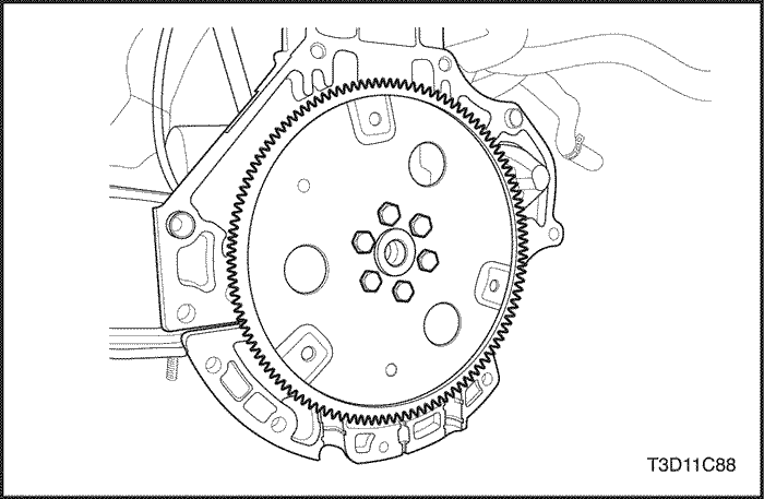
- Remove the flywheel or flexible plate bolts.
- Remove the flywheel or the flexible plate.
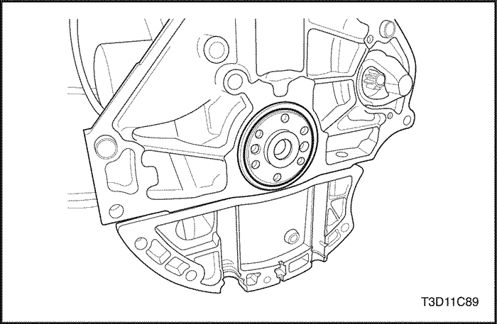
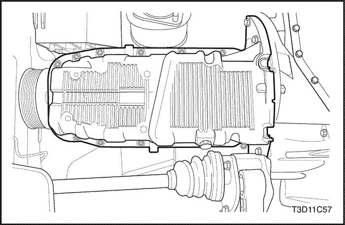
- Remove the crankshaft rear oil seal.
- Mount the engine assembly on the engine overhaul stand KM-412.
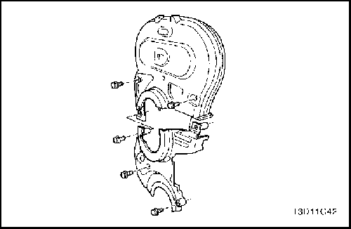
- Remove the upper and lower front timing belt cover bolts.
- Remove the upper and lower front timing belt cover.
- Slightly loosen the coolant pump retaining bolts.
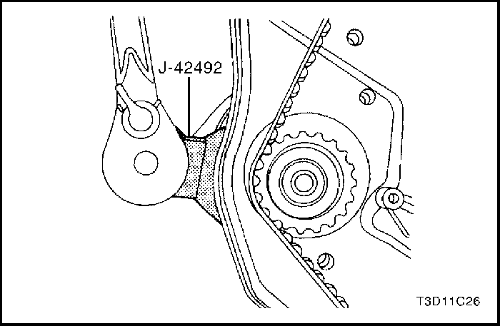
- Rotate the coolant pump using the timing belt adjuster J-42942 to remove the tension from the timing belt.
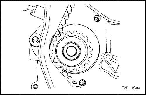
- Remove the timing belt.
- Disconnect the crankcase ventilation tubes from the cylinder head cover.
- Remove the engine beautification cover bolts.
- Remove the engine beautification cover.
- Disconnect the ignition wires from the spark plugs.
- Remove the cylinder head cover nuts.
- Remove the cylinder head cover washers.
- Remove the cylinder head cover and the cylinder head cover gasket.
Notice : Take extreme care to prevent any scratches, nicks or damage to the camshafts.
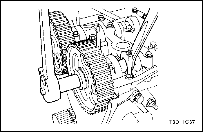
- While holding the intake camshaft firmly in place, remove the intake camshaft bolt.
- Remove the intake camshaft gear.
- While holding the exhaust camshaft firmly in place, remove the exhaust camshaft bolt.
- Remove the exhaust camshaft gear.
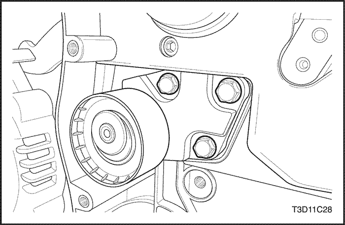
- Remove the timing belt automatic tensioner bolts.
- Remove the timing belt automatic tensioner.
- Remove the timing belt idler pulley bolt.
- Remove the timing belt idler pulley.
- Remove the crankshaft timing belt gear.
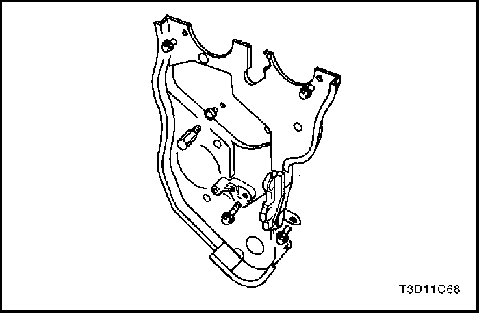
- Remove the rear timing belt cover bolts.
- Remove the rear timing belt cover.
- Rotate the engine on the engine overhaul stand KM-412.
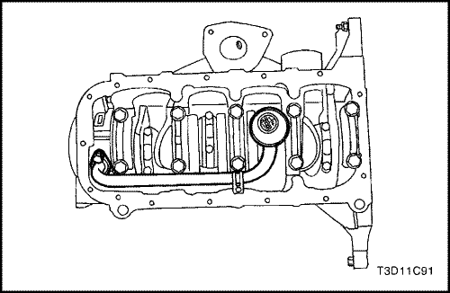
- Remove the oil pan retaining bolts.
- Remove the oil pan.
- Remove the oil pickup tube bolts.
- Remove the oil pickup tube.
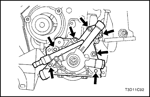
- Remove the oil pump retaining bolts.
- Remove the oil pump.
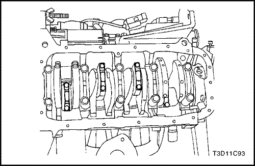
- Mark the order of the connecting rod bearing caps.
- Remove the connecting rod bearing cap bolts for all of the pistons.
- Remove the connecting rod bearing caps and the lower connecting rod bearings.
- Remove the upper connecting rod bearings.
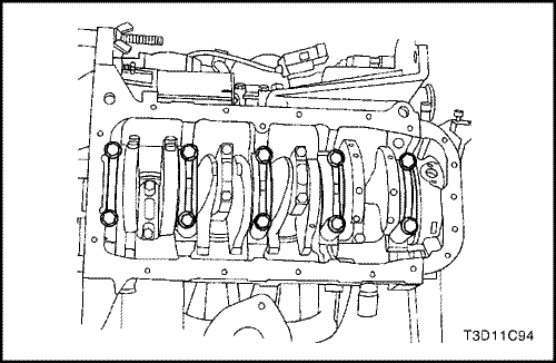
- Mark the order of the crankshaft bearing caps.
- Remove the crankshaft bearing cap bolts.
- Remove the crankshaft bearing caps and the lower crankshaft bearings.
- Remove the crankshaft.
- Remove the upper crankshaft bearings.
- Clean any parts that need it.
Assembly Procedure
- Coat the crankshaft bearings with engine oil.
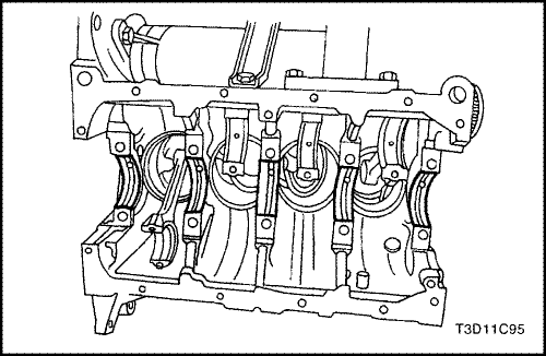
- Install the upper crankshaft bearings in the engine block.
- Install the crankshaft.
- Install the lower crankshaft bearings in the bearing caps.
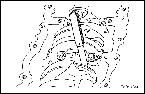
- Inspect the crankshaft end play with the crankshaft bearings installed.
- Check for permissible crankshaft end play. Refer to "Engine Specifications" in this section.
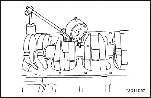
- With the crankshaft mounted on the front and rear crankshaft bearings, check the middle crankshaft journal for permissible out-of-round (runout). Refer to "Engine Specifications"in this section.
Important : Grease the crankshaft journals and lubricate the crankshaft bearings slightly so that the plastic gauging thread does not tear when the crankshaft bearing caps are removed.
- Inspect all of the crankshaft bearing clearances using a commercially available plastic gauging which is available in different tolerance ranges.
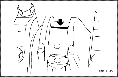
- Cut the plastic gauging threads to the length of the bearing width. Lay them between the crankshaft journals and the crankshaft bearings.
- Install the crankshaft bearing caps and the bolts.
Tighten
Tighten the crankshaft bearing cap bolts to 50 N•m (37 lb-ft) plus 45 degrees.
- Remove the crankshaft bearing cap bolts and the caps.
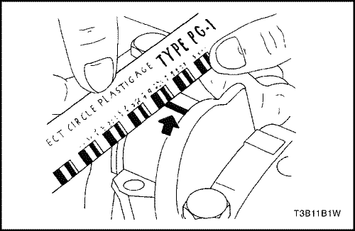
- Measure the width of the flattened plastic thread of the plastic gauging using a ruler.
- Inspect the bearing clearance for permissible tolerance ranges. Refer to "Engine Specifications" in this section.
- Apply a bead of adhesive sealing compound to the grooves of the crankshaft bearing caps.
- Install the crankshaft bearing caps to the engine block.
- Tighten the crankshaft bearing caps using new bolts.
Tighten
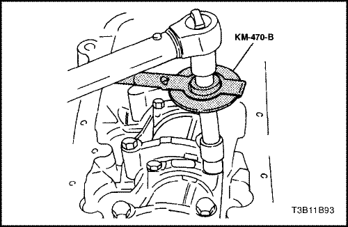
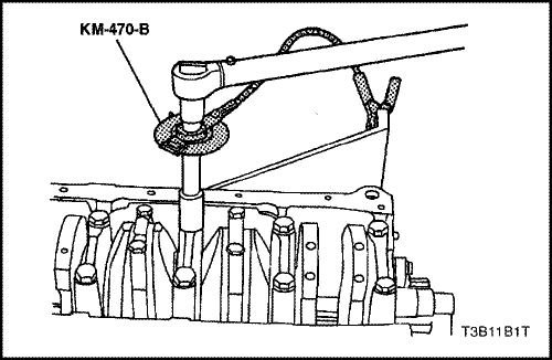
Tighten the crankshaft bearing cap bolts to 50 N•m (37 lb-ft) using a torque wrench. Use the angular torque gauge KM-470-B to tighten the crankshaft bearings 45 degrees.
Important : Grease the connecting rod journals and lubricate the connecting rod bearings slightly so that the plastic gauging thread does not tear when the connecting rod bearing caps are removed.
- Inspect all of the connecting rod bearing clearances using plastic gauging.
- Cut the plastic gauging threads to the length of the connecting rod bearing width. Lay them between the connecting rod journals and the connecting rod bearings.
- Install the connecting rod bearing caps.
Tighten
Tighten the connecting rod bearing cap bolts to 25 N•m (18 lb-ft) using a torque wrench. Use the angular torque gauge KM-470-B to tighten the connecting rod bearing cap bolts to 30 degrees plus 15 degrees.
- Remove the connecting rod bearing caps.
- Measure the width of the flattened plastic thread of the plastic gauging using a ruler.
- Inspect the bearing clearance for permissible tolerance ranges. Refer to "Engine Specifications" in this section.
- Install the connecting rod bearing caps to the connecting rods.
- Tighten the connecting rod bearing caps using new bolts.
Tighten
Tighten the connecting rod bearing cap bolts to 25 N•m (18 lb-ft) using a torque wrench. Use the angular torque gauge KM-470-B to tighten the connecting rod cap bolts to 30 degrees plus 15 degrees.
- Install the oil pump.
- Install the oil pump retaining bolts.
Tighten
Tighten the oil pump retaining bolts to 10 N•m (89 lb-in).
- Install the oil pump pickup tube.
- Install the oil pump pickup tube bolts.
Tighten
Tighten the oil pump pickup tube bolts to 10 N•m (89 lb-in).
- Install the oil pan gasket to the oil pan.
- Install the oil pan.
Important : Install the oil pan within 5 minutes after applying the liquid gasket to the oil pan.
- Install the oil pan retaining bolts.
Tighten
Tighten the oil pan retaining bolts to 10 N•m (89 lb-in).
- Rotate the engine on the engine overhaul stand KM-412.
- Install the rear timing belt cover.
- Install the rear timing belt cover bolts.
Tighten
Tighten the rear timing belt cover bolts to 10 N•m (89 lb-in).
- Install the crankshaft timing belt gear.
- Install the timing belt automatic tensioner.
- Install the timing belt automatic tensioner bolts.
Tighten
Tighten the timing belt automatic tensioner bolts to 25 N•m (18 lb-ft).
- Install the timing belt idler pulley.
- Install the timing belt idler pulley bolt.
Tighten
Tighten the timing belt idler pulley bolt to 40 N•m (30 lb-ft).
Notice : Take extreme care to prevent any scratches, nicks or damage to the camshafts.
- Install the intake camshaft gear.
- Install the intake camshaft gear bolt while holding the intake camshaft firmly in place.
Tighten
Tighten the intake camshaft gear bolt to 67.5 N•m (49 lb-ft).
- Install the exhaust camshaft gear.
- Install the exhaust camshaft gear bolt while holding the exhaust camshaft firmly in place.
Tighten
Tighten the exhaust camshaft bolt to 67.5 N•m (49 lb-ft).
- Install the timing belt. Refer to "Timing Belt" in this section.
- Adjust the timing belt tension. Refer to "Timing Belt Check and Adjust" in this section.
- Apply a small amount of gasket sealant to the corners of the front camshaft caps and to the top of the rear cylinder head cover-to-cylinder head seal.
- Install the cylinder head cover and the cylinder head cover gasket.
- Install the cylinder head cover washers.
- Install the cylinder head cover nuts.
Tighten
Tighten the cylinder head cover nuts to 9 N•m (80 lb-in).
- Connect the ignition wires to the spark plugs.
- Install the engine beautifiction cover.
- Install the engine beautifiction cover bolts.
Tighten
Tighten the engine beautifiction cover bolts to 3 N•m (27 lb-in).
- Connect the crankcase ventilation tube to the cylinder head cover.
- Install the upper and lower front timing belt cover.
- Install the upper and lower front timing belt cover bolts.
Tighten
Tighten the upper and lower front timing belt cover bolts to 10 N•m (89 lb-in).
- Install the power steering pump, if equipped.
- Install the power steering pump mounting bolts.
Tighten
Tighten the power steering pump mounting bolts to 25 N•m (18 lb-ft).
- Install the engine lifting device.
- Remove the engine from the engine overhaul stand KM-412.
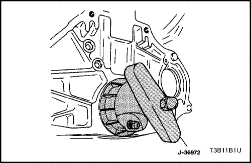
- Install a new crankshaft rear oil seal using installer J-36972 or KM-635.
- Install the flywheel or flexible plate.
- Install the flywheel or the flexible plate bolts.
Tighten
Tighten the flywheel bolts to 35 N•m (25 lb-ft). Use the angular torque gauge KM-470-B to tighten the flywheel bolts 30 degrees plus 15 degrees. For the manual transaxle, tighten the flexible plate bolts to 60 N•m (44 lb-ft).
- Install the engine. Refer to "Engine" in this section.
Crankshaft Bearings and Connecting Rod Bearings - Gauging Plastic
Tools Required
KM-470-B Angular Torque Gauge
Inspection Procedure - Crankshaft
- Coat the crankshaft bearings with engine oil.
- Install the upper crankshaft bearings into the engine block crankshaft journals.
- Install the lower crankshaft bearings into the crankshaft bearing caps.
- Install the lower crankshaft bearings into the crankshaft bearing caps.
- Install the crankshaft.
- Inspect the crankshaft end play with the crankshaft bearings installed.
- Check for permissible crankshaft end play. Refer to "Engine Specifications" in this section.
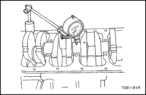
- With the crankshaft mounted on the front and rear crankshaft bearings, check the middle crankshaft journal for permissible out-of-round (runout). Refer to "Engine Specifications" in this section.
Notice : Grease the crankshaft journals and lubricate the crankshaft bearings slightly so that the plastic gauging thread does not tear when the crankshaft bearing caps are removed.
- Inspect all of the crankshaft bearing clearances using a commercially available plastic gauging which is available in different tolerance ranges.
- Cut the plastic gauging threads to the length of the bearing width. Lay them between the crankshaft journals and the crankshaft bearings.
- Install the crankshaft bearing caps.
- Install the crankshaft bearing cap bolts.
Tighten
Tighten the crankshaft bearing cap bolts to 50 N•m (37 lb-ft). Using the angular torque gauge KM-470-B, tighten the crankshaft bearing cap bolts 45 degrees plus 15 degrees.
- Remove the crankshaft bearing caps.
- Measure the width of the flattened plastic thread of the plastic gauging using a ruler.
- Inspect the bearing clearances for permissible tolerance ranges. Refer to "Engine Specifications" in this section.
Inspection Procedure - Connecting Rods
- Coat the connecting rod bearings with engine oil.
- Install the upper connecting rod bearings into the connecting rod journals.
- Install the lower connecting rod bearings into the connecting rod bearing caps.
Notice : Grease the connecting rod journals and lubricate the connecting rod bearings slightly so that the plastic gauging thread does not tear when the connecting rod bearing caps are removed.
- Inspect all of the connecting rod bearing clearances using a plastic gauging.
- Cut the plastic gauging threads to the length of the bearing width. Lay them axially between the connecting rod journals and the connecting rod bearings.
- Install the connecting rod bearing caps.
- Install the connecting rod bearing cap bolts.
Tighten
Tighten the connecting rod bedaring cap bolts to 25 N•m (18 lb-ft). Using the angular torque gauge KM-470-B, tighten the connecting rod cap bolts 30 degrees.
- Remove the connecting rod bearing caps.
- Measure the width of the flattened plastic thread of the plastic gauging using a ruler.
- Inspect the bearing clearance for permissible tolerance ranges. Refer to "Engine Specifications" in this section.
 | |  | |
| © Copyright Chevrolet Europe. All rights reserved |


