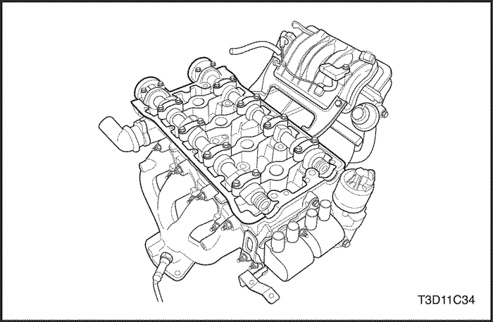
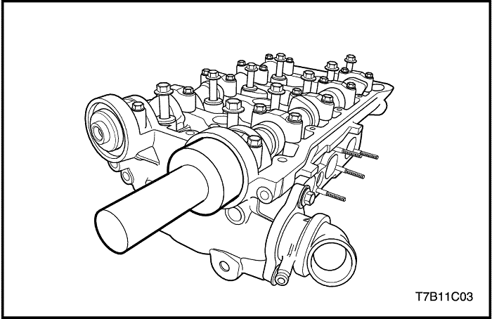
- Install the cylinder head gasket.
- Install the cylinder head with the intake manifold and the exhaust manifold attached.
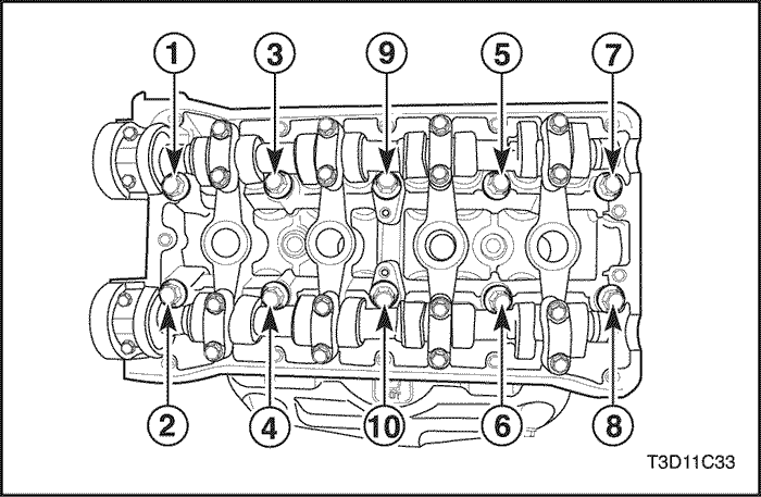
- Install the cylinder head bolts.
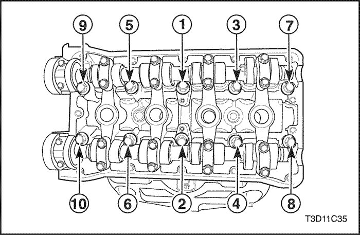
- Tighten the cylinder head bolts gradually in the sequence shown.
Tighten
Tighten the cylinder head bolts to 25 N•m (18 lb-ft). Adjust the bolts to 60 degrees plus 60 degrees plus 60 degree plus 10 degrees using the angular torque gauge KM-470-B.
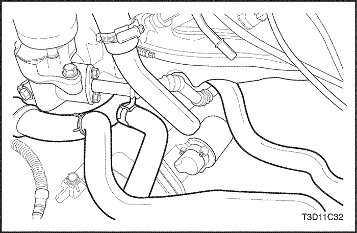


- Connect the heater outlet hose from the coolant pipe.
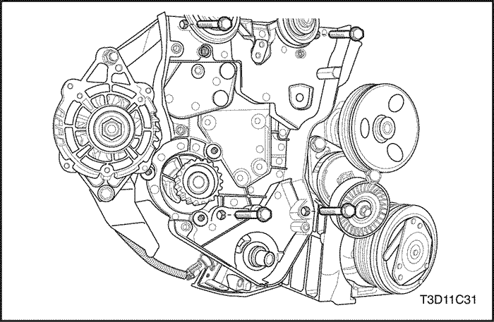
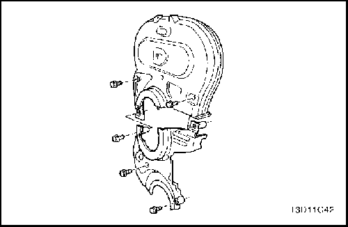
- Install the rear timing belt cover.
- Install the rear timing belt cover bolts.
Tighten
Tighten the rear timing belt cover bolts to 10 N•m (89 lb-in).
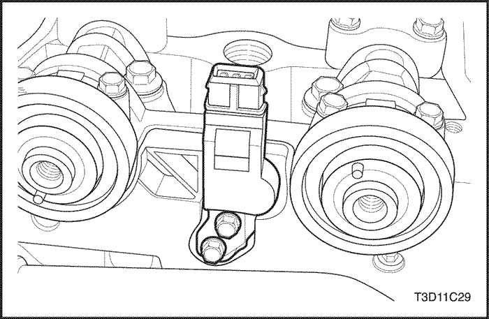
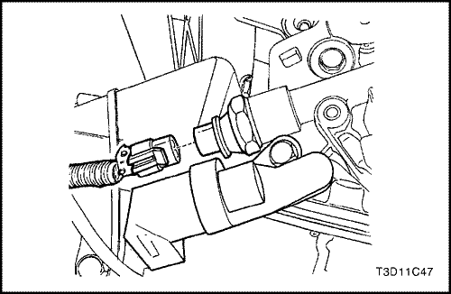
- Install the camshaft position (CMP) sensor.
- Install the camshaft position (CMP) sensor bolts.
Tighten
Tighten the camshaft position (CMP) sensor bolts to 12 N•m (106 lb-in).
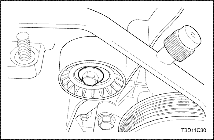
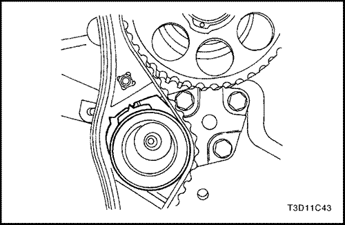
- Install the timing belt idler pulley.
- Install the timing belt idler pulley bolt.
Tighten
Tighten the timing belt idler pulley bolt to 40 N•m (30 lb-ft).
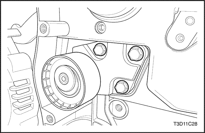
- Install the timing belt automatic tensioner.
- Install the timing belt automatic tensioner bolts.
Tighten
Tighten the timing automatic tensioner belts to 25 N•m (18 lb-ft).
Notice : Take extreme care to prevent any scratches, nicks or damage to the camshafts.
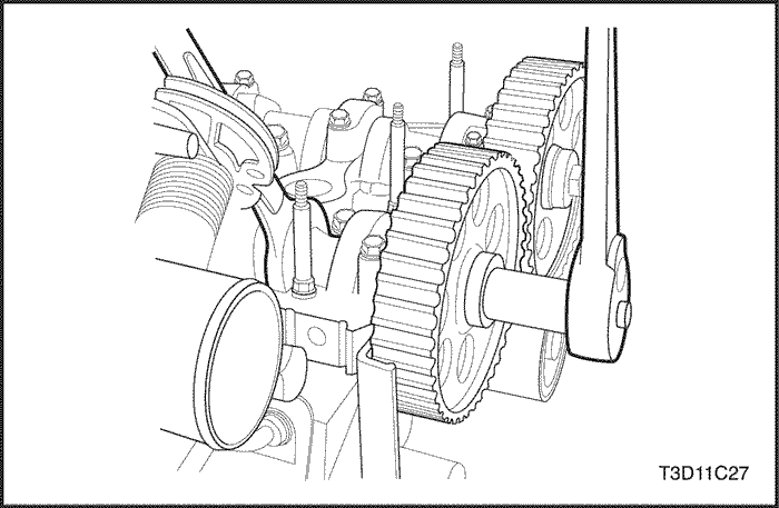
- Install the intake camshaft gear.
- While holding the intake camshaft firmly in place, install the intake camshaft gear bolt.
Tighten
Tighten the intake camshaft gear bolt to 67.5 N•m (49 lb-ft).
- Install the exhaust camshaft gear.
- While holding the exhaust camshaft firmly in place, install the exhaust camshaft gea bolt.
Tighten
Tighten the exhaust camshaft gear bolt to 67.5 N•m (49 lb-ft).
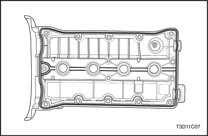
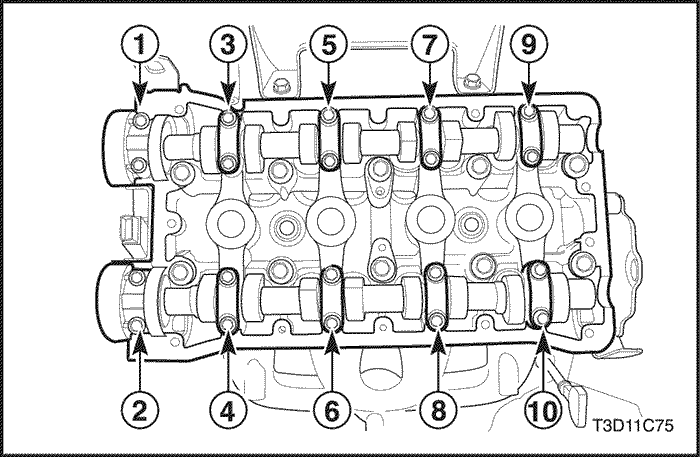
- Apply a small amount of gasket sealant to the corners of the front camshaft caps, and the top ot the rear cylinder head cover to cylinder head seal.
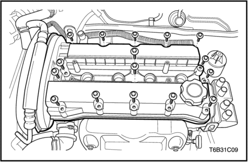
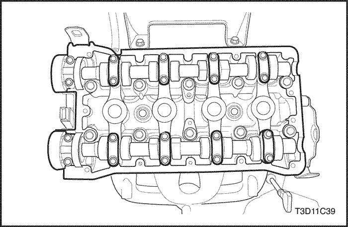
- Install the cylinder head cover and the cylinder head cover gasket.
- Install the cylinder head cover bolts.
Tighten
Tighten the cylinder head cover bolts to 10 N•m (89 lb-in).
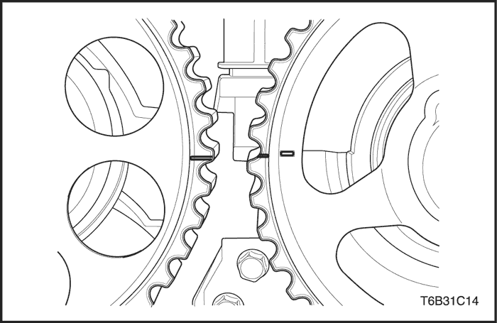
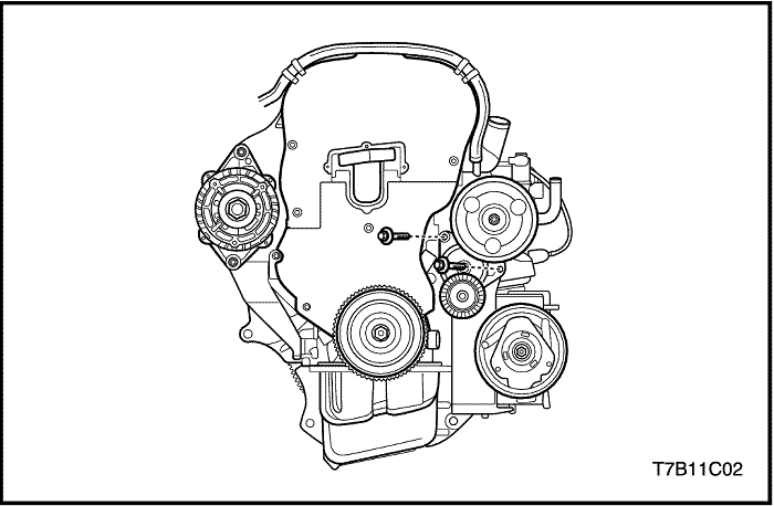
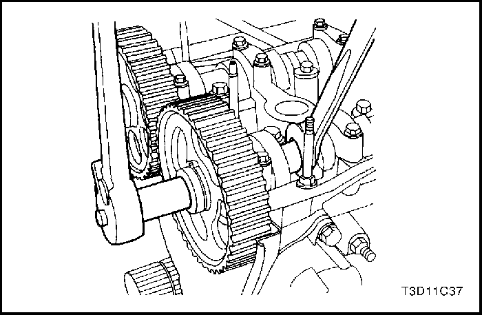
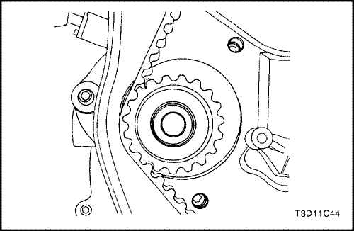
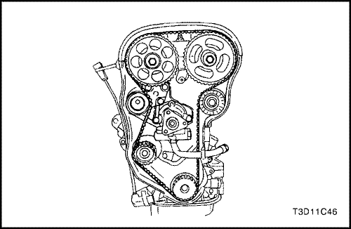
- Align the timing marks on the camshaft gear.
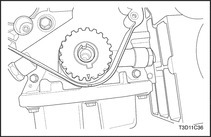
- Align the mark on the crankshaft gear to the notch at the bottom of the rear timing belt cover.
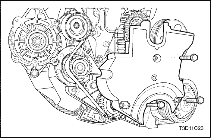
- Install the timing belt.
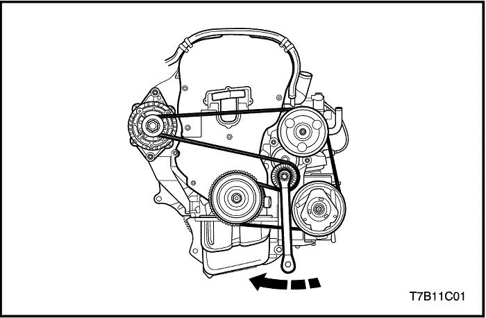
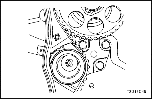
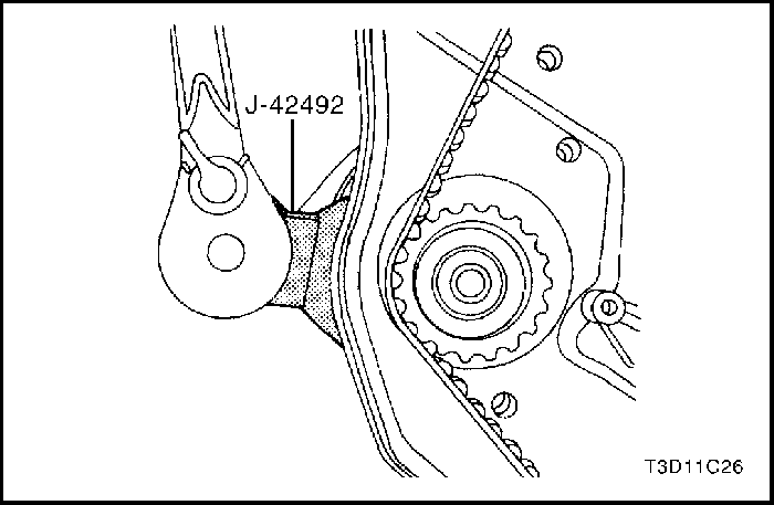
- Rotate the coolant pump clockwise using the timing belt adjuster J-42492 to apply tension to the timing belt.
Tighten
Tighten the coolant pump retaining bolt to 10 N•m (89 lb-in).
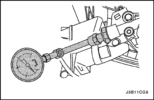
- Check and adjust the timing belt tension. Refer to "Timing Belt Check and Adjust" in this section.
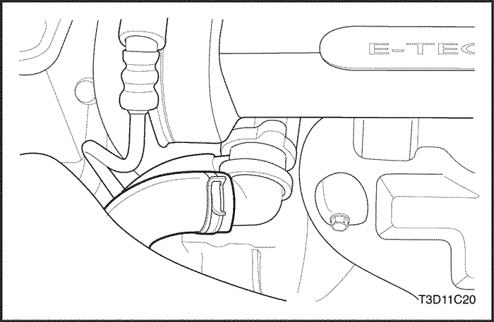
- Install the engine mount-to-engine mount bracket retaining bolts.
Tighten
Tighten the engine mount-to-engine mount bracket retaining bolts to 60 N•m (44 lb-ft).
- Install the lower front timing belt cover.
- Install the lower front timing belt cover bolts.
Tighten
Tighten the lower front timing belt cover bolts to 10 N•m (89 lb-in).
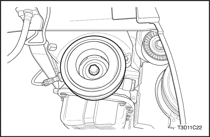
- Install the crankshaft pulley.
- Install the crankshaft pulley bolt.
Tighten
Tighten the crankshaft pulley bolt to 95 N•m (70 lb-ft) using a torque wrench. Using the angular torque gauge KM-470-B, tighten the crankshaft pulley bolt to 30 degrees plus 15 degrees.
- Install the upper front timing belt cover.
- Install the upper front timing belt cover bolts.
Tighten
Tighten the upper front timing belt cover bolts to 10 N•m (89 lb-in).
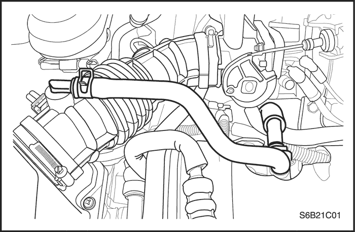
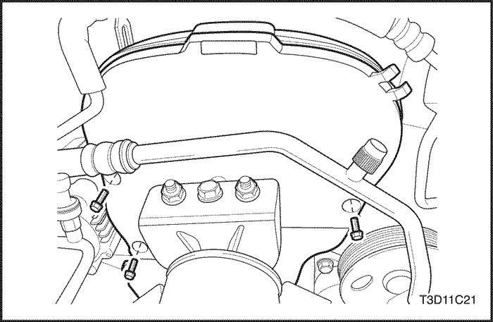
- Connect the upper radiator hose from the thermostat housing.
- Connect the throttle body coolant hose at the thermostat housing.
- Install the catalytic converter retaining nuts at the exhaust manifold flange.
Tighten
Tighten the catalytic converter retaining nuts to 40 N•m (30 lb-ft).
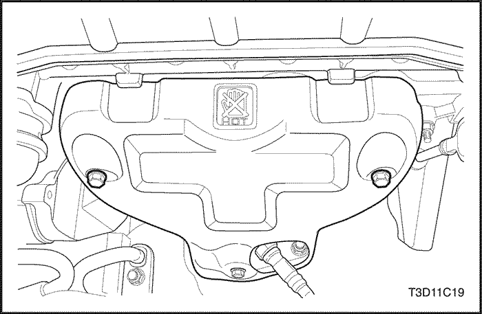
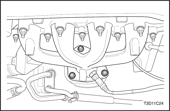
- Install the exhaust manifold heat shield.
- Install the exhaust manifold heat shield bolts.
Tighten
Tighten the exhaust manifold heat shield bolts to 15 N•m (11 lb-ft).
- Connect the engine coolant temperature (ECT) sensor connector.
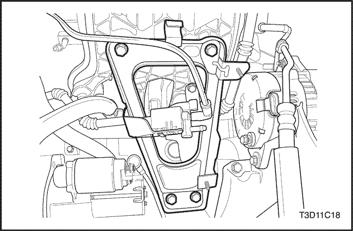
- Install the intake manifold support bracket upper bolts.
Tighten
Tighten the intake manifold support bracket upper bolts to 25 N•m (18 lb-ft).
- Install the canister purge solenoid valve at the intake manifold support bracket.
- Install the engine under cover.
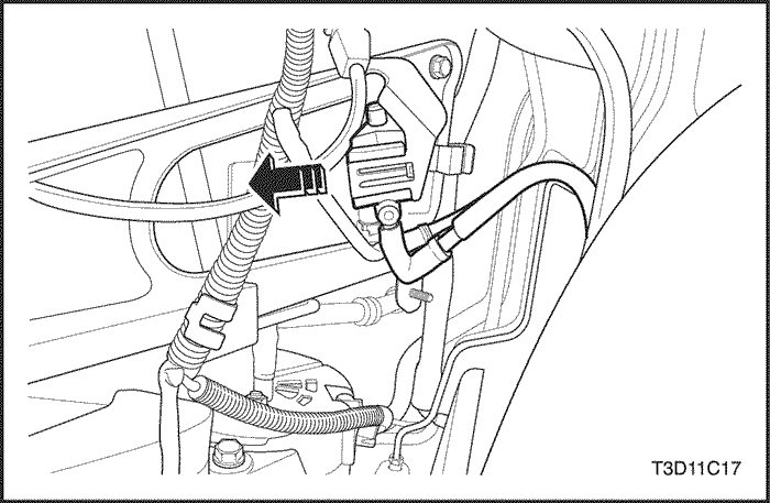
- Connect the front heated oxygen sensor connector.
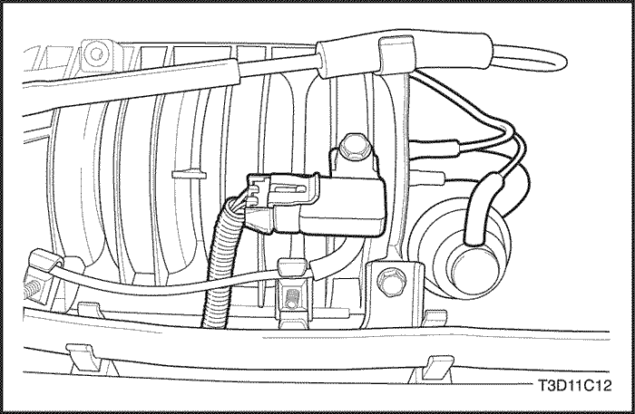
- Connect the electronic ignition system ignition coil connector.
- Connect the exhaust gas recirculation (EGR) valve connector.
- Install the accessory drive belt.
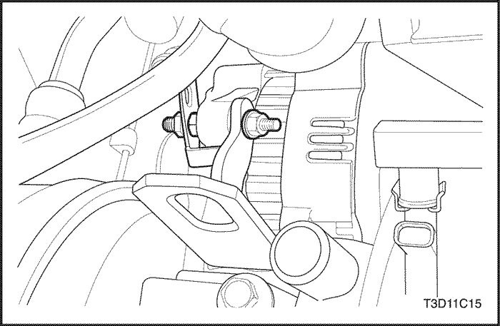
- Install the alternator bracket retaining nut.
Tighten
Tighten the alternator bracket retaining nut to 25 N•m (18 lb-ft).
- Install the alternator nut. Do not tighten.
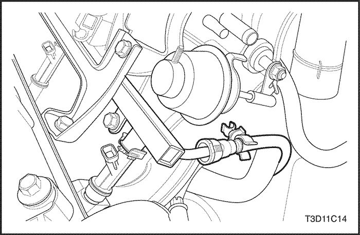
- Connect the fuel line at the fuel rail. Refer to Section 1F, Engine Controls.
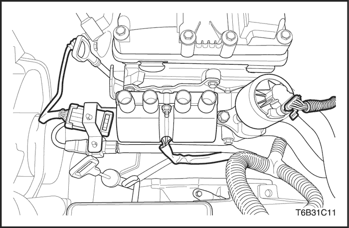
- Connect the fuel injector harness connectors.
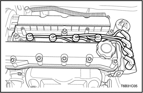
- Connect the ignition wires from the spark plugs.
- Connect the camshaft position (CMP) sensor connector.
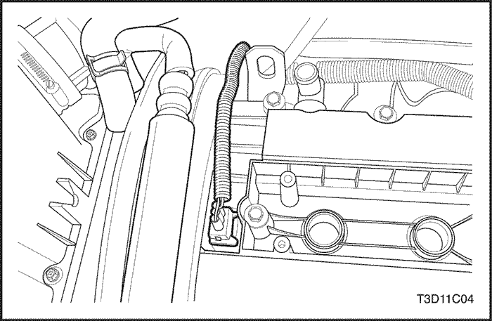
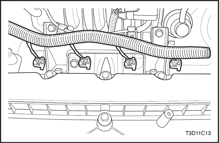
- Connect the crankcase ventilation tube from the cyliner head cover.
- Connect the breather tube from the cyliner head cover.
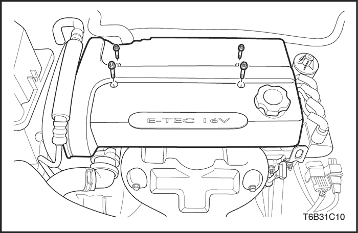
- Install the engine beautification cover.
- Install the engine beautification cover bolts.
- Connect the variable geometry induction solenoid (VGIS) vacuum tank hose.
- Connect the VGIS connector.
- Connect the brake booster vacuum hose.
- Connect the MAP sensor connector.
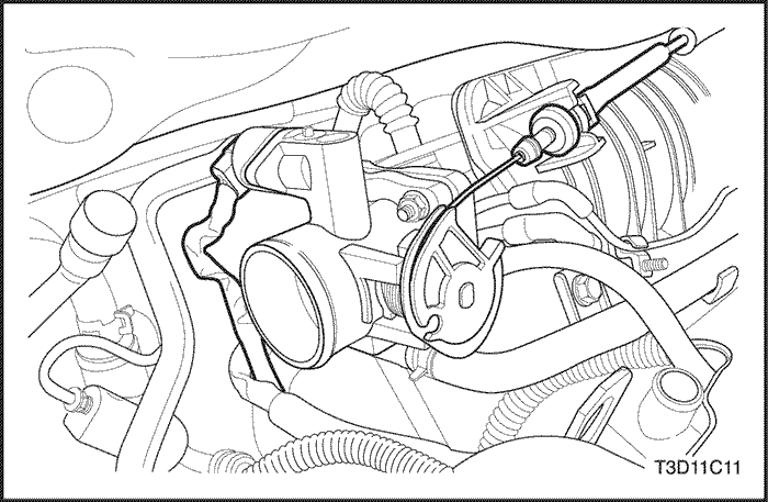
- Connect the engine coolant In-let/Out-let hose from the throttle body.
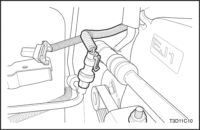
- Connect the throttle cable from the throttle body and the intake manifold.
- Connect the TPS connector.
- Connect the IAC valve connector.
- Connect the A/C pressue transducer connector.
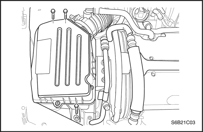
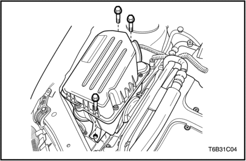
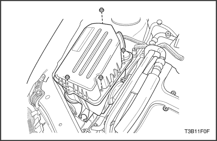
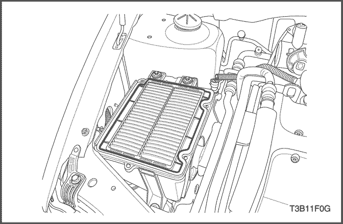
- Install the air filter housing.
- Install the air filter housing bolts.
Tighten
Tighten the air filter housing bolts to 8 N•m (71 lb-in).
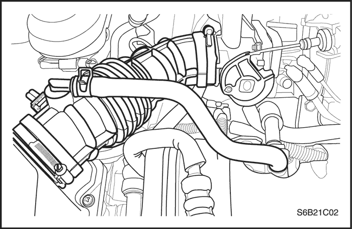
- Connect the air intake tube from the throttle body.
- Connect the IAT sensor connector.
- Connect the breather tube from the cylinder head cover.
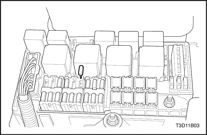
- Install the fuel pump fuse.
- Connect the negative battery cable.
- Refill the engine cooling system Refer to Section 1D, Engine Cooling.