

Oil Pump
Removal Procedure
- Disconnect the negative battery cable.
- Remove the power steering pump, if equipped. Refer to Section 6B, Power Steering Pump.
- Remove the timing belt. Refer to "Timing Belt" in this section.
- Remove the rear timing belt cover. Refer to "Rear Timing Belt Cover" in this section.
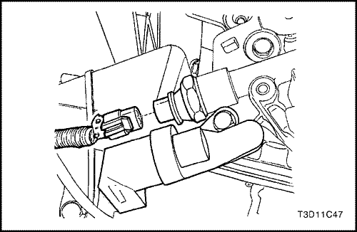
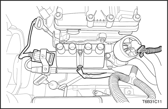
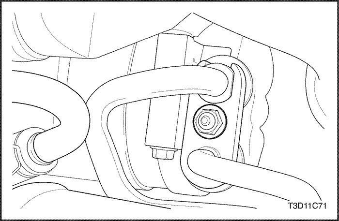
- Disconnect the oil pressure switch connector.
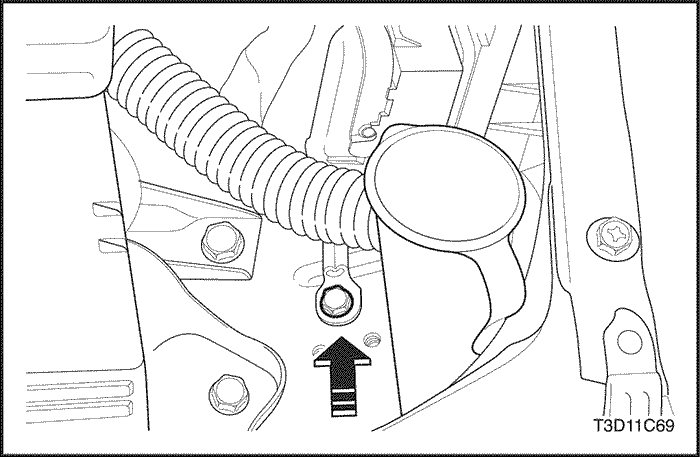
- Remove the crankshaft position (CKP) sensor bolt.
- Remove the CKP sensor.
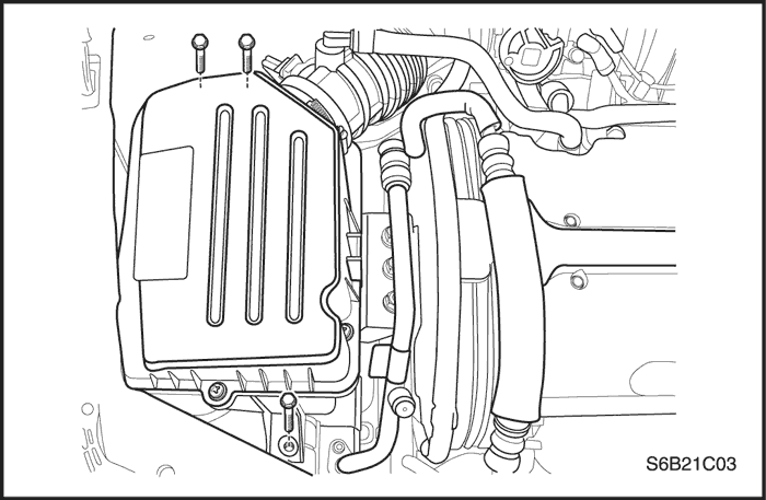
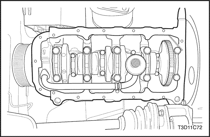
- Remove the oil pan. Refer to "Oil Pan"in this section.
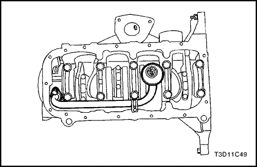
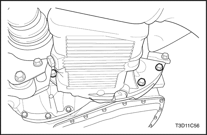
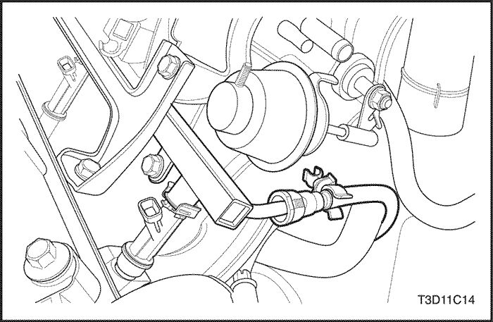
- Remove the oil pump pickup tube and the support bracket bolts.
- Remove the oil pump pickup tube.
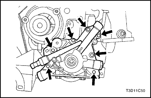
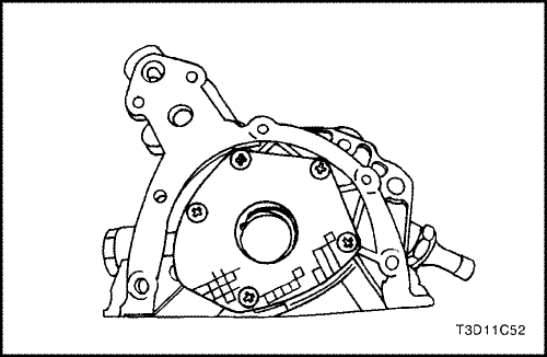
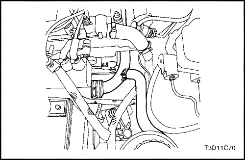
- Remove the oil pump retaining bolts.
- Carefully separate the oil pump and the gasket from the engine block and the oil pan.
- Remove the oil pump.
Inspection Procedure
- Clean the oil pump and the engine block gasket mating surfaces.
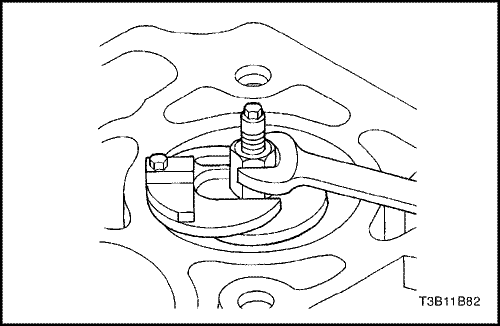
- Remove the safety relief valve bolt.
- Remove the safety relief valve and the spring.
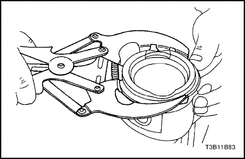
- Remove the oil pump-to-crankshaft seal.
- Remove the oil pump rear cover bolts.
- Remove the rear cover.
- Clean the oil pump housing and all of the parts of the oil pump housing.
- Inspect all of the parts for signs of wear. Refer to Engine Specifications" in this section.
- Coat all of the oil pump parts with clean engine oil and reinstall them.
Notice : Pack the oil pump gear cavity with petroleum jelly to ensure an oil pump prime, or engine damage could result.
- Apply Loctite® 242 to the rear cover bolts and install the rear oil pump cover with the bolts.
Tighten
Tighten the oil pump rear cover bolts to 6 N•m (53 lb-in).
- Install the safety relief valve, the spring, the washer, and the bolt.
Tighten
Tighten the oil pump safety relief valve bolt to 30 N•m (22 lb-ft).
Installation Procedure
- Apply Loctite® 242 to the oil pump bolts and room temperature vulcanizing (RTV) sealer to the new oil pump gasket.
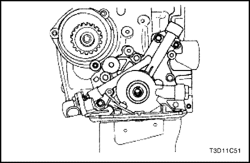
- Install the gasket to the oil pump and install the oil pump to the engine block with the retaining bolts.
Tighten
Tighten the oil pump retaining bolts to 10 N•m (89 lb-in).
- Install a new oil pump-to-crankshaft seal. Coat the lip of the seal with a thin coat of grease.
- Coat the threads of the oil pump pickup tube and support bracket bolts with Loctite® 242.
- Install the oil pump pickup tube and bolts.
Tighten
Tighten the oil pump pickup tube and the support bracket bolts to 10 N•m (89 lb-in).
- Install the oil pan. Refer to "Oil Pan" in this section.
- Install the CKP sensor and the bolt.
Tighten
Tighten the crankshaft position sensor retaining bolt to 10 N•m (89 lb-in).
- Connect the oil pressure switch connector.
- Install the rear timing belt cover. Refer to "Rear Timing Belt Cover" in this section.
- Install the timing belt. Refer to "Timing Belt"in this section.
- Connect the negative battery cable.
Oil Pan
Removal Procedure
- Disconnect the negative battery cable.
- Remove the right front wheel. Refer to Section 2E, Tires and Wheels.
- Remove the right front splash shield.
- Drain the engine oil from the engine crankcase.
- Disconnect the heated oxygen sensor.
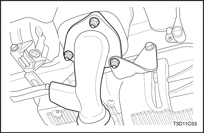
- Remove the catalytic lower flange nuts from the exhaust manifold and the bolts at the bracket.
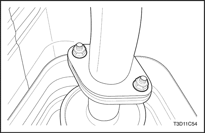
- Remove the nuts that secure the front pipe.
- Remove the catalytic converter and the exhaust pipe as a unit.
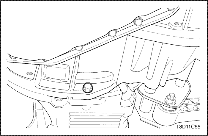
- Remove the oil pan to transaxle housing bolts.
- Remove the transaxle housing to oil pan bolt.
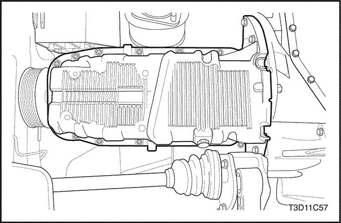
- Remove the oil pan retaining bolts.
- Remove the oil pan from the engine block.
- Remove the oil pan gasket from the oil pan.
Cleaning Procedure
- Clean the oil pan sealing surface.
- Clean the engine block sealing surface.
- Clean the oil pan retaining bolts.
- Clean the oil pan attaching bolt holes in the engine block.
Installation Procedure
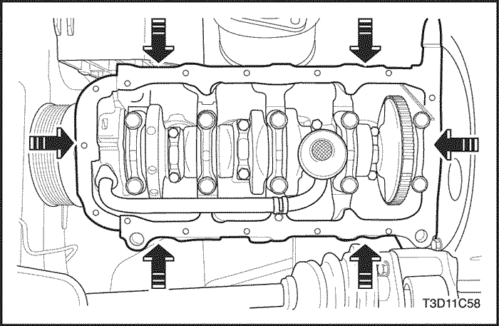
- Install the oil pan gasket to the oil pan.
- Install the oil pan to the engine block.
Important : Install the oil pan within 5 minutes after applying the liquid gasket to the oil pan.
- Install the oil pan retaining bolts.
Tighten
Tighten the oil pan retaining bolts to 10 N•m (89 lb-in).
- Install the transaxle housing to oil pan bolt.
Tighten
Tighten the transaxle housing to oil pan bolt to 25 N•m (18 lb-ft).
- Install the oil pan to transaxle housing bolts.
Tighten
Tighten the oil pan to transaxle housing bolts to 25 N•m (18 lb-ft).
- Install the catalytic converters and the exhaust pipe as a unit.
Tighten
Tighten the catalytic converter-to-exhaust manifold nuts and the exhaust pipe bracket bolts to 50 N•m (37 lb-ft).
Tighten
Tighten the front muffler nuts to 30 N•m (22 lb-ft).
- Connect the heated oxygen sensor.
- Install the right front splash shield.
- Install the right front wheel. Refer to Section 2E, Tires and Wheels.
- Connect the negative battery cable.
- Refill the engine crankcase with engine oil.
Engine Mount
Tools Required
DW110-060 Engine Assembly Lift Support
Removal Procedure
- Disconnect the negative battery cable.
- Remove the upper radiator cover.
- Remove the right front splash shield.
- Support the engine assembly using the engine assembly lift support DW110-060.
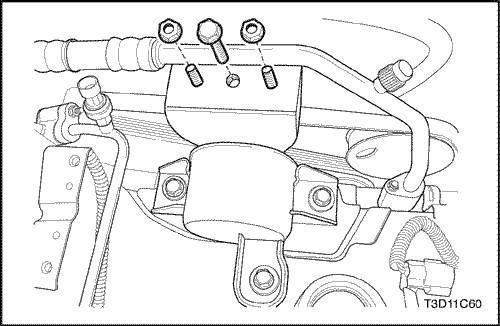
- Remove the engine mount bracket retaining bolts.
- Remove the engine mount retaining nuts.
- Lower the engine.
- Remove the engine mount.
Installation Procedure
- Install the engine mount.
- Raise the engine.
- Install the engine mount retaining nuts.
Tighten
Tighten the engine mount retaining nuts to 40 N•m (30 lb-ft).
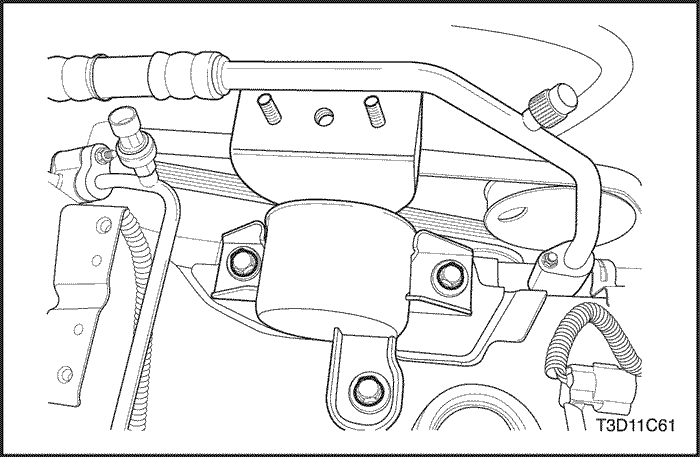
- Install the engine mount bracket retaining bolts.
Tighten
Tighten the engine mount bracket retaining bolts to 65 N•m (48 lb-ft).
- Remove engine assembly lift support DW110-060.
- Install the right front splash shield.
- Install the upper radiator cover.
- Connect the negative battery cable.
Intake Manifold
Removal Procedure
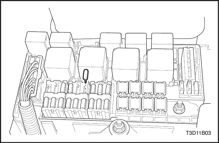
- Remove the fuel pump fuse.
- Start the engine. Crank the engine for 10 seconds after it stalls to rid the fuel system of fuel pressure.
- Disconnect the negative battery cable.
- Drain the engine coolant. Refer to Section 1D, Engine Cooling.
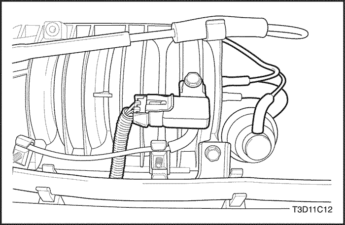
- Disconnect the intake air temperature (IAT) sensor connector.
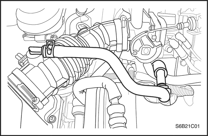
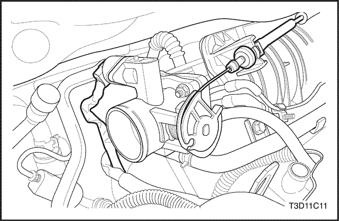
- Disconnect the air intake tube from the throttle body.
- Disconnect the idle air control (IAC) valve connector.
- Disconnect the throttle position sensor (TPS) connector.
- Remove the alternator adjusting bolt and the alternator drive belt.
- Disconnect the engine coolant temperature (ECT) sensor connector.
- Disconnect the heater inlet hose from the cylinder head.
- Disconnect the surge tank coolant hose at the throttle body.
- Disconnect all of the necessary vacuum hoses, including the vacuum hose at the fuel pressure regulator and the brake booster vacuum hose at the intake manifold.
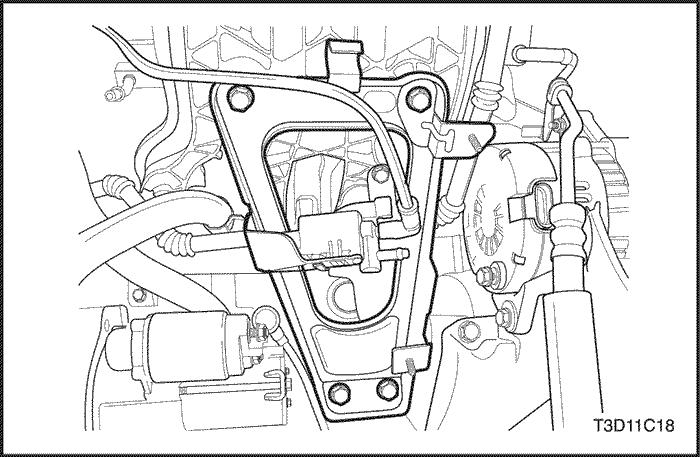
- Disconnect the throttle cable from the throttle body and the intake manifold.
- Remove the fuel injector rail and fuel injectors as an assembly. Refer to Section 1F, Engine Controls.
- Remove the alternator adjusting bracket bolt from the intake manifold.
- Remove the alternator adjusting bracket.
- Remove the intake manifold support bracket bolts and the intake manifold.
- Remove the intake manifold support bracket.
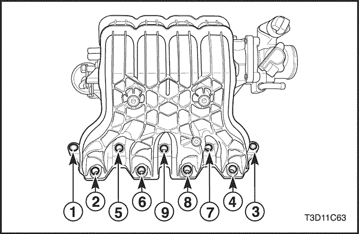
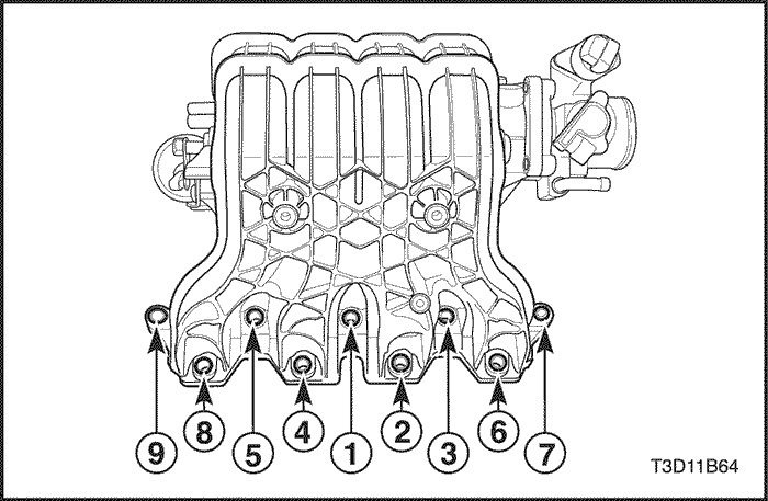
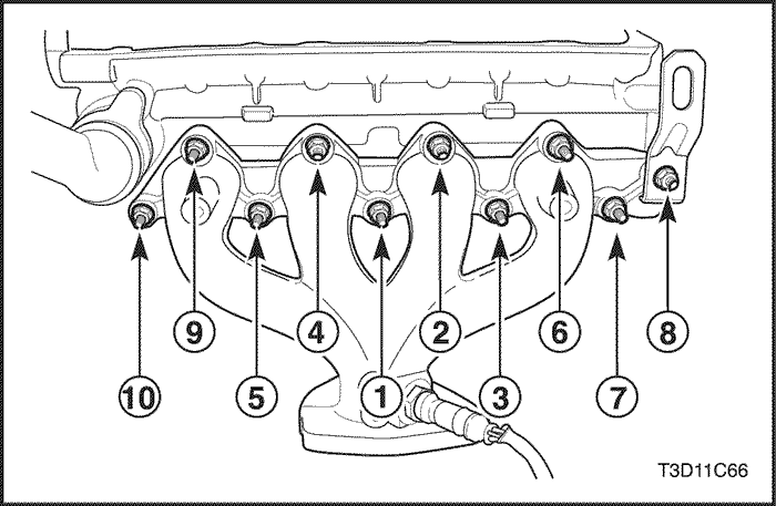
- Remove the intake manifold retaining nuts/bolts in the sequence shown.
- Remove the intake manifold.
- Remove the intake manifold gasket.
- Clean the sealing surfaces of the intake manifold and the cylinder head.
Installation Procedure
- Install the intake manifold gasket.
- Install the intake manifold.
- Install the intake manifold retaining nuts/bolts in the sequence shown.
Tighten
Tighten the intake manifold retaining nuts/bolts to 25 N•m (18 lb-ft).
- Install the intake manifold support bracket.
- Install the intake manifold support bracket upper bolts to the intake manifold.
Tighten
Tighten the intake manifold support bracket upper bolts to 25 N•m (18 lb-ft).
- Install the intake manifold support bracket lower bolt-to-engine block.
Tighten
Tighten the intake manifold support bracket lower bolt-to-engine block to 40 N•m (30 lb-ft).
- Install the fuel rail and fuel injectors as an assembly. Refer to Section 1F, Engine Controls.
- Connect the throttle cable to the intake manifold and the throttle body.
- Connect all of the necessary vacuum lines that were previously disconnected.
- Connect the heater inlet hose to the cylinder head.
- Connect the surge tank coolant hose to the throttle body.
- Install the alternator adjusting bracket at the intake manifold.
- Install the alternator adjusting bracket bolt.
Tighten
Tighten the alternator adjusting bracket bolts to 15 N•m (11 lb-ft).
- Install the alternator adjusting bolt and the alternator driver belt.
Tighten
Tighten the alternator adjusting belts to 15 N•m (11 lb-ft).
- Connect the ECT sensor connector.
- Connect the IAC valve connector.
- Connect the TPS connector.
- Connect the air intake tube to the throttle body.
- Connect the IAT sensor connector.
- Connect the PCM/ECM ground terminal to the intake manifold.
- Install the fuel pump fuse.
- Connect the negative battery cable.
- Refill the engine cooling system. Refer to Section 1D, Engine Cooling.
Exhaust Manifold
Removal Procedure
- Disconnect the negative battery cable.
- Disconnect the pre-converter oxygen sensor connector.
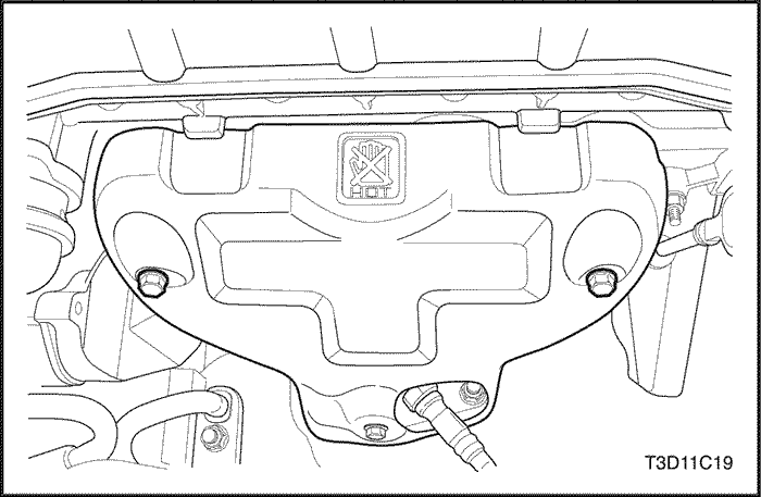
- Remove the exhaust manifold heat shield bolts.
- Remove the exhaust manifold heat shield.
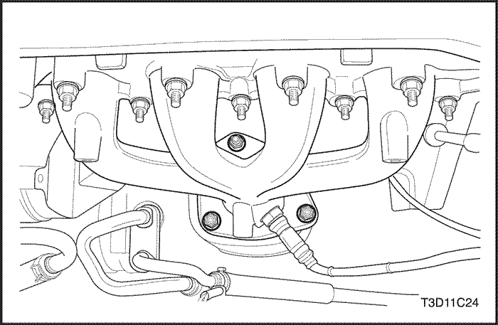
- Remove the auxiliary catalytic converter nuts from the exhaust manifold.
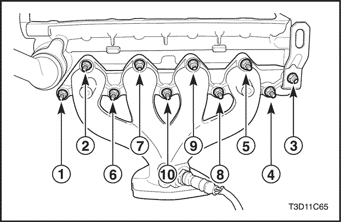
- Remove the exhaust manifold retaining nuts in the sequence shown.
- Remove the exhaust manifold.
- Remove the exhaust manifold gasket.
- Clean the sealing surfaces of the exhaust manifold and the cylinder head.
Installation Procedure
- Install the exhaust manifold gasket.
- Install the exhaust manifold.
- Install the exhaust manifold retaining nuts and tighten them in the sequence shown.
Tighten
Tighten the exhaust manifold retaining nuts 25 N•m (18 lb-ft).
- Install the auxiliary catalytic converter nuts to the exhaust manifold.
Tighten
Tighten the auxiliary catalytic converter-to-exhaust manifold nuts to 40 N•m (30 lb-ft).
- Install the exhaust manifold heat shield.
- Install the exhaust manifold heat shield bolts.
Tighten
Tighten the exhaust manifold heat shield bolts to 15 N•m (11 lb-ft).
- Connect the pre-converter oxygen sensor connector.
- Connect the negative battery cable.
Camshaft Gears
Removal Procedure
- Disconnect the negative battery cable.
- Remove the timing belt. Refer to "Timing Belt" in this section.
- Remove the engine beautifiction cover bolts.
- Remove the engine beautifiction cover.
- Disconnect the ignition wires from the spark plugs.
- Disconnect the crankcase ventilation tubes from the cylinder head cover.
- Disconnect the camshaft position (CMP) sensor.
- Remove the cylinder head cover nuts.
- Remove the cylinder head cover washers.
- Remove the cylinder head cover and the cylinder head cover gasket.
Notice : Take extreme care to prevent any scratches, nicks or damage to the camshafts.
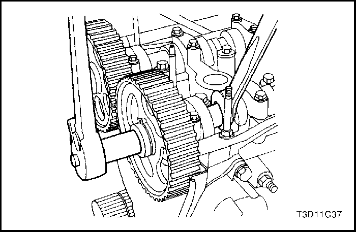
- While holding the intake camshaft firmly in place, remove the intake camshaft gear bolt.
- Remove the intake camshaft gear.
- While holding the exhaust camshaft firmly in place, remove the exhaust camshaft gear bolt.
- Remove the exhaust camshaft gear.
Installation Procedure
Notice : Take extreme care to prevent any scratches, nicks or damage to the camshafts.
- Install the intake camshaft gear.
- While holding the intake camshaft firmly in place, install the intake camshaft gear bolt.
Tighten
Tighten the intake camshaft gear bolt to 67.5 N•m (49 lb-ft).
- Install the exhaust camshaft gear.
- While holding the exhaust camshaft firmly in place, install the exhaust camshaft gear bolt.
Tighten
Tighten the exhaust camshaft gear bolt to 67.5 N•m (49 lb-ft).
- Apply a small amount of gasket sealant to the corners of the front camshaft caps and to the top of the rear cylinder head cover-to-cylinder head seal.
- Install the cylinder head cover and the cylinder head cover gasket.
- Install the cylinder head cover washers.
- Install the cylinder head cover nuts.
Tighten
Tighten the cylinder head cover nuts to 9 N•m (80 lb-in).
- Connect the crankcase ventilation tubes to the cylinder head cover.
- Connect the ignition wires to the spark plugs.
- Install the engine beautification cover.
- Install the engine beautification cover bolts.
Tighten
Tighten the engine beautification cover bolts to 3 N•m (27 lb-in).
- Install the timing belt. Refer to "Timing Belt" in this section.
- Connect the CMP.
- Connect the negative battery cable.
Rear Timing Belt Cover
Removal Procedure
- Remove the timing belt and the timing belt cover. Refer to "Timing Belt" in this section.
- Remove the camshaft gears. Refer to "Camshaft Gears"in this section.
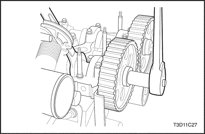
- Remove the crankshaft gear.
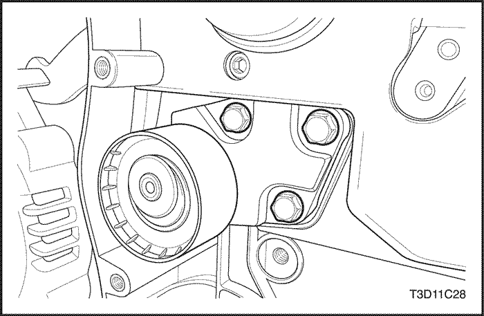
- Remove the timing belt automatic tensioner bolts.
- Remove the timing belt automatic tensioner.
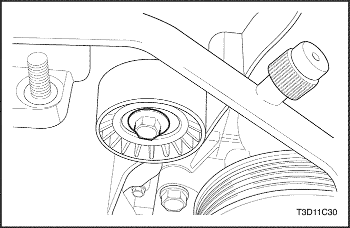
- Remove the timing belt idler pulley bolt.
- Remove the timing belt idler pulley.
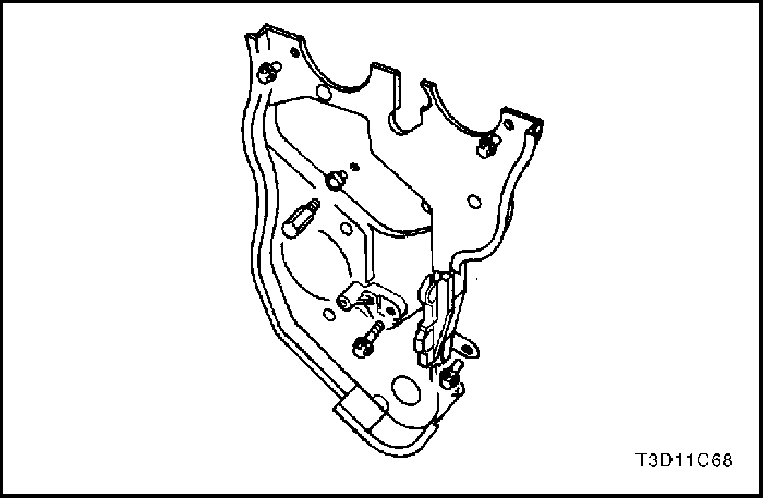
- Remove the rear timing belt cover bolts.
- Remove the rear timing belt cover.
Installation Procedure
- Install the rear timing belt cover.
- Install the rear timing belt cover bolts.
Tighten
Tighten the rear timing belt cover bolts to 10 N•m (89 lb-in).
- Install the timing belt idler pulley.
- Install the timing belt idler pulley bolt.
Tighten
Tighten the timing belt idler pulley bolt to 40 N•m (30 lb-ft).
- Install the timing belt automatic tensioner.
- Install the timing belt automatic tensioner bolts.
Tighten
Tighten the timing belt automatic tensioner bolts to 25 N•m (18 lb-ft).
- Install the crankshaft gear.
- Install the camshaft gears. Refer to "Camshaft Gears"in this section.
- Install the timing belt and timing belt cover. Refer to "Timing Belt" in this section.

Engine
Tools Required
KM-470-B Angular Torque Gauge
Removal Procedure
Important : On vehicles equipped with a manual transaxle, the manual transaxle must be removed before the engine is removed. Refer to Section 5B, Manual Transaxle. - Remove the fuel pump fuse.
- Start the engine. Crank the engine for 10 seconds after it stalls to rid the fuel system of fuel pressure.
- Remove the hood. Refer to Section 9R, Body Front End.
- Drain the engine oil.
- Disconnect the negative battery cable.
- Disconnect and separate the positive battery cable.
- Disconnect the negative battery cable from the vehicle frame.
- Discharge the air conditioning (A/C) system, if equipped. Refer to Section 7B, Manual Control Heating, Ventilation, and Air Conditioning System.
- Disconnect the intake air temperature (IAT) sensor connector.
- Remove the air intake tube from the throttle body and air filter housing.
- Disconnect the breather tubes from the valve cover.
- Remove the right front wheel. Refer to Section 2E, Tires and Wheels.
- Remove the right front splash shield.
- Remove the accessory drive belt, if equipped.
- Remove the alternator adjusting bolt.
- Drain the engine coolant. Refer to Section 1D, Engine Cooling.
- Remove the cooling system radiator and the engine cooling fans. Refer to Section 1D, Engine Cooling.
- Disconnect the upper radiator hose from the thermostat housing.
- Disconnect the power steering return hose from the power steering pump, if equipped. Refer to Section 6A, Power Steering System.
- Disconnect the power steering pressure hose from the power steering pump, if equipped. Refer to Section 6A, Power Steering System.
- Disconnect the electrical connector at the electronic ignition (EI) system ignition coil and the powertrain control module/engine control module (PCM/ECM) ground terminal at the intake manifold and at the starter motor.
- Disconnect the oxygen sensor connector.
- Disconnect the fuel injector harness connectors.
- Disconnect the idle air control (IAC) valve connector.
- Disconnect the throttle position sensor (TPS) connector.
- Disconnect the engine coolant temperature (ECT) sensor connector.
- Disconnect the alternator voltage regulator connector.
- Remove the engine beautification cover bolts.
- Remove the engine beautification cover.
- Disconnect the camshaft position (CMP) sensor.
- Disconnect all of the necessary vacuum lines including the brake booster vacuum hose.
- Disconnect the fuel feed line at the fuel rail.
- Disconnect the throttle cable from the throttle body and the intake manifold bracket.
- Disconnect the surge tank coolant hose at the throttle body.
- Disconnect the heater outlet hose at the coolant pipe.
- Disconnect the heater inlet hose from the cylinder head.
- Disconnect the surge tank coolant hose from the coolant pipe.
- Disconnect the lower radiator hose from the coolant pipe.
- Disconnect the starter solenoid "S" terminal wire.
- Remove the A/C compressor hose assembly retaining bolt.
- Disconnect the A/C compressor hose assembly from the compressor.
- Disconnect the electrical connector at the A/C compressor coil.
- Remove the power steering hose from the power steering pump.
- Remove the catalytic converter lower flange nuts from the exhaust manifold studs and the bolts at the bracket.
- Remove the nuts that secure the front muffler pipe.
- Remove the front exhaust pipe as a unit.
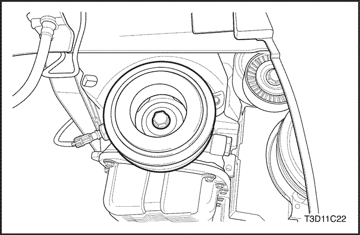
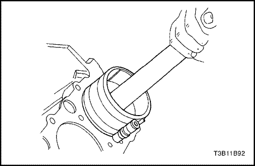
- Remove the crankshaft pulley bolt.
- Remove the crankshaft pulley.
- Disconnect the vacuum lines at the evaporative (EVAP) emission canister purge solenoid.
- Disconnect the electrical connector at the EVAP emissions charcoal canister purge solenoid.
- Disconnect the electrical connector at the oil pressure switch.
- Disconnect the crankshaft position (CKP) sensor and the knock sensor connectors.
- Remove the CKP sensor retaining bolt.
- Remove the CKP sensor.
- Install the engine lifting device.
- Remove the service hall cover.
- Remove the torque conver bolts. Refer to Section 5A, Aisin Automatic Transaxle.
- Remove the power steering hoses and pipes. Refer to Section 6A, Power Steering System.
- Remove the cross member by removing the nuts and the bolts to underbody.
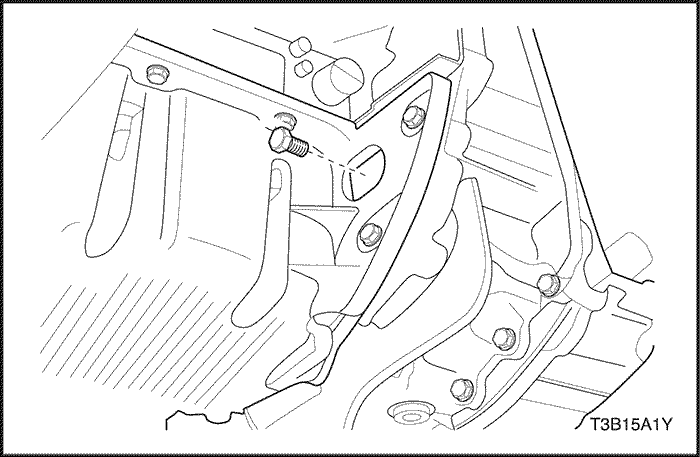
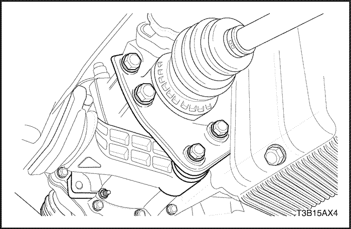
- Disconnect the right engine mount bracket from the engine mount by removing the retaining bolts.
- Remove the right engine mount bracket from the engine block.
- Separate the engine block from the transaxle.
- Remove the engine.
Installation Procedure
- Install the engine into the engine compartment.
- Install the right engine mount bracket to the engine block.
- Install the right engine mount bracket retaining bolts.
Tighten
Tighten the engine mount bracket retaining bolts to 60 N•m (44 lb-ft).
- Connect the right engine mount bracket to the engine mount by installing the two retaining bolts.
Tighten
Tighten the engine mount-to-engine mount bracket retaining bolts to 60 N•m (44 lb-ft).
- Remove the floor jack used for support of the transaxle.
- Remove the engine lifting device.
- Install the transaxle torque converter bolts on vehicles equipped with an automatic transaxle.
Tighten
Tighten the transaxle torque converter bolts to 65 N•m (48 lb-ft).
- Install the rear mounting bracket bolts and the bracket.
Tighten
Tighten the rear mounting bracket bolts to 60N•m (44 lb-ft).
- Install the damping block connection nut and bolt. Refer to Section 5A, Aisin Automatic Transaxle.
- Connect the vacuum lines at the EVAP charcoal canister purge solenoid.
- Connect the electrical connector to the EVAP emission canister purge solenoid.
- Connect the oil pressure switch connector.
- Install the crankshaft pulley.
- Install the crankshaft pulley bolt.
Tighten
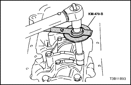
Tighten the crankshaft pulley bolt to 95 N•m (70 lb-ft) using a torque wrench. Using the angular torque gauge KM-470-B, tighten the crankshaft pulley bolt 30 degrees plus 15 degrees.
- Install the CKP sensor and the CKP sensor retaining bolt.
Tighten
Tighten the crankshaft position sensor retaining bolt to 10 N•m (89 lb-in).
- Connect the CKP sensor and the knock sensor connectors.
- Install the catalytic converter and the exhaust pipe as a unit.
Tighten
Tighten the catalytic converter-to-exhaust manifold nuts and the bolts at the bracket to 40 N•m (30 lb-ft).
Tighten
Tighten the front muffler nuts to 30 N•m (22 lb-ft).
- Connect the power steering pressure hose, if equipped. Refer to Section 6A, Power Steering System.
- Connect the A/C compressor coil connector, if equipped.
- Connect the ECT sensor connector.
- Install the alternator adjusting bolt.
- Install the accessory drive belt, if equipped.
- Connect the A/C compressor hose assembly and the A/C compressor hose assembly retaining bolt, if equipped.
Tighten
Tighten the A/C compressor hose assembly retaining bolt to 33 N•m (24 lb-ft).
- Install the right front splash shield.
- Install the right front wheel. Refer to Section 2E, Tires and Wheels.
- Connect the fuel feed line to the fuel rail.
- Connect all of the necessary vacuum lines including the brake booster vacuum hose.
- Connect the oxygen sensor connector.
- Connect the starter solenoid "S" terminal wire.
- Connect the alternator voltage regulator connector.
- Connect the TPS connector.
- Connect the IAC valve connector.
- Connect the CMP sensor.
- Install the engine beautification cover.
- Install the engine beautification cover bolts.
Tighten
Tighten the engine beautification cover bolts to 3 N•m (27 lb-in).
- Connect the fuel injector harness connectors.
- Connect the electrical connector at the EI system ignition coil and the PCM/ECM ground terminal at the intake manifold and the starter motor.
- Install the air intake tube between the throttle body and the air filter housing.
- Connect the breather tubes to the cylinder head cover.
- Connect the IAT sensor connector.
- Install the cooling system radiator and the engine cooling fans. Refer to Section 1D, Engine Cooling.
- Connect the lower radiator hose to the coolant pipe.
- Connect the upper radiator hose to the thermostat housing.
- Connect the heater inlet hose to the cylinder head.
- Connect the heater outlet hose to the coolant pipe.
- Connect the coolant surge tank hose to the coolant pipe.
- Connect the surge tank coolant hose to the throttle body.
- Connect the throttle cable to the throttle body and the intake manifold bracket.
- Install the fuel pump fuse.
- Connect the negative battery cable to the vehicle frame.
- Connect the negative battery cable.
- Connect and assemble the positive battery cable.
- Refill the engine crankcase with engine oil.
- Refill the engine coolant system. Refer to Section 1D, Engine Cooling.
- Bleed the power steering system, if equipped. Refer to Section 6A, Power Steering System.
- Refill the A/C refrigerant system, if equipped. Refer to Section 7B, Manual Control Heating, Ventilation, and Air Conditioning System.
- Install the hood. Refer to Section 9R, Body Front End.
Pistons and Rods
Tools Required
KM-427 Piston Pin Service Set
KM 470-B Angular Torque Gauge
Removal Procedure
- Remove the cylinder head with the intake manifold and exhaust manifold attached. Refer to "Cylinder Head and Gasket" in this section.
- Remove the oil pan. Refer to "Oil Pan" in this section.
- Remove the oil pump pickup tube bolts.
- Remove the oil pump pickup tube.
- Move the piston to the bottom of the piston stroke.
- Mark the connecting rod cap for position.
- Remove the connecting rod cap bolts.
- Remove the connecting rod cap and lower connecting rod bearing.
- Remove the upper piston connecting rod bearing.
- Ridge ream the cylinder wall.
Caution : Use care when handling the piston. Worn piston rings are sharp and may cause injury.
- Remove the piston.
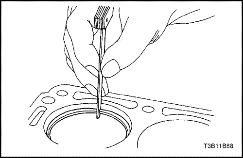
- Use a piston ring expander tool to expand the piston rings.
- Remove the piston rings.
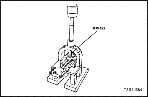
- Remove the piston pin from the piston and connecting rod assembly using the piston pin service set KM-427.
- Separate the piston from the connecting rod.
Inspection Procedure
- Inspect the connecting rod for bending or twisting. If the connecting rod is bent or twisted, replace the connecting rod.
- Inspect the connecting rod bearings.
- Inspect the connecting rod lower end for wear.
- Inspect the connecting rod upper end for scoring.
- Inspect the crankshaft rod bearing journal for wear. Refer to "Engine Specifications" in this section.
- Inspect the piston for scoring, cracks, and wear.
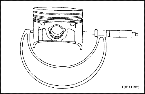
- Inspect the piston for taper using a micrometer.
- Inspect the piston for fit to the connecting rod.
- Inspect the engine block deck surface for flatness using a straight edge and a feeler gauge. Refer to "Engine Specifications" in this section.
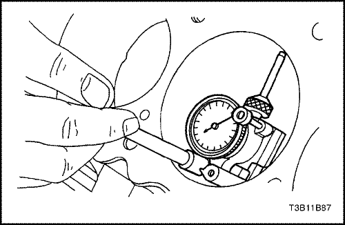
- Inspect the bearing bore for concentricity and alignment using a bore gauge. Refer to "Engine Specifications" in this section. If the bearing bore is beyond specifications, replace the engine block.
- Inspect the engine block cylinder bore for wear, runout, ridging and taper using a bore gauge. Refer to "Engine Specifications" in this section.
- Inspect the engine block cylinder bore for glazing. Lightly hone the cylinder bore as necessary.
Installation Procedure
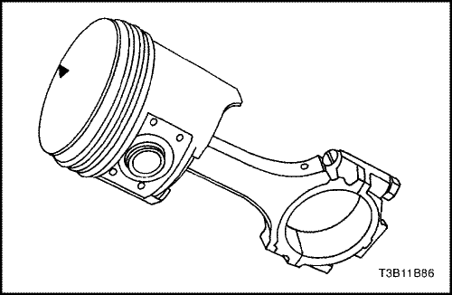
- Align the notch on the piston and connecting rod so that the proper sides will be facing the front of the engine.
- Install the piston pin guide through the piston and the connecting rod.
- Coat the piston pin with clean oil.
- Install the piston pin into the opposite side of the piston.
- Install the piston pin into the piston and connecting rod assembly using the piston pin service set KM-427.
- Select a set of new piston rings.
- Measure the piston ring gap using a feeler gauge. Refer to "Engine Specifications" in this section.
- Increase the piston ring gap by carefully filing off excess material if the piston ring gap is below specifications.
- Measure the piston ring side clearance using a feeler gauge. Refer to "Engine Specifications" in this section.
- If the piston ring is too thick, try another piston ring.
- If no piston ring can be found that fits to specifications, the piston ring may be ground to size with emery paper placed on a sheet of glass.
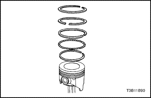
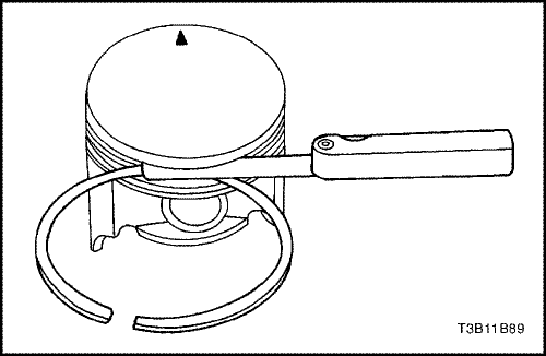
- Install a piston oil ring, the expander, then the second piston oil ring to the bottom ring groove of the piston.
- Install the second compression ring to the middle ring groove of the piston.
- Install the top compression ring to the top ring groove of the piston.
- Use a piston ring expander to install the piston rings. Do not expand the piston rings beyond the expansion necessary for installation.
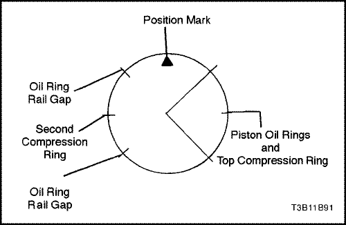
- Stagger the piston oil rings, the oil ring rail gaps, the second compression ring, and the top compression ring in relation to the notch on the top of the piston.
- Lubricate the cylinder wall and the piston rings with clean engine oil.
- Install the piston using a ring compressor and a wood handle. Guide the lower connecting rod end to prevent damaging the crankshaft journal.
- Install the connecting rod cap and bearings. Refer to "Crankshaft Bearings and Connecting Rod Bearings - Gauging Plastic" in this section.
- Install the connecting rod bearing cap bolts.
Tighten
Tighten the connecting rod bearing cap bolts to 25 N•m (18 lb-ft). Using the angular torque gauge KM 470-B, tighten the bolts one turn of 30 degrees plus.
- Install the oil pump pickup tube.
- Install the oil pump pickup tube bolts.
Tighten
Tighten the oil pump pickup tube bolts to 10 N•m (89 lb-in).
- Install the oil pan. Refer to "Oil Pan" in this section.
- Install the cylinder head with the intake manifold and exhaust manifold attached. Refer to "Cylinder Head and Gasket" in this section.
 | |  | |
| © Copyright Chevrolet Europe. All rights reserved |


