SECTION 2C
FRONT SUSPENSION
SPECIFICATIONS
General Specifications
Application | Trim Height |
Center of Front Wheel to Bottom of Front Wheel Well | 344 mm (13.5 in.) |
Center of Rear Wheel to Bottom of Rear Wheel Well | 343 mm (13.5 in.) |
Fastener Tightening Specifications
Application | N•m | Lb-Ft | Lb-In |
Ball Joint-to-Control Arm Nuts | 150 | 111 | 1328 |
Ball Joint-to-Knuckle/Strut Nut | 55 | 41 | 487 |
Control Arm Front Mounting Bolts | 110 | 81 | 972 |
Drive Axle-to-Hub Caulking Nut | 300 | 221 | 2655 |
Piston Rod Nut | 60 | 44 | 531 |
Stabilizer Shaft-to-Iink nut | 50 | 37 | - |
Strut Assembly-to-Body Nuts | 60 | 44 | 531 |
Strut Cartridge Closure Nut | 200 | 148 | 1776 |
SPECIAL TOOLS
Special Tools Table
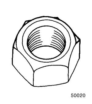
 
| 500-20 Hex Nut |
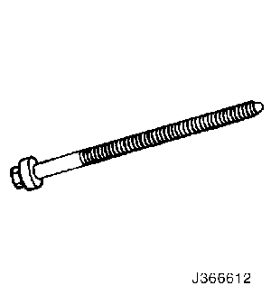
| J-36661-2 Forcing Screw |
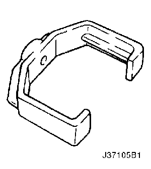
| J-37105-B-1 Support Bridge |
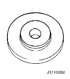
| J-37105-B-2 Bearing Adapter |
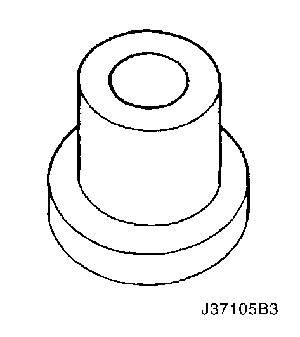
| J-37105-B-3 Hub Adapter |
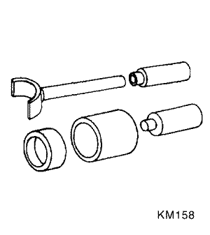
| KM-158 Remover/Installer |
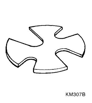
| KM-307-B Removal Plate |
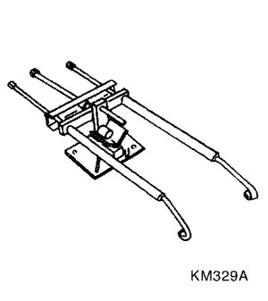
| KM-329-A Spring Compressor |
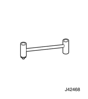
| J-42468 Front Strut Mount Nut Wrench |
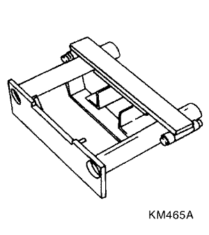
| KM-465-A Front Spring Compressor |
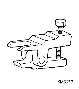
| KM-507-B Ball Joint Remover |
| KM-508-A Remover/Installer |
DIAGNOSIS
Strut Dampener
A strut dampener is basically a shock absorber. However, strut dampeners are easier to extend and retract by hand than are shock absorbers. Strut dampeners are used only on the front in most vehicles, including this vehicle. Shock absorbers are used on the rear wheels.
Struts Seem Weak
Checks | Action |
Check the tire pressures. | Adjust the tire pressures to the specifications on thetire placard. |
Check the load conditions under which the vehicle isnormally driven. | Consult with the owner to confirm the owner’sunderstanding of normal load conditions. |
Check the compression and rebound effectiveness ofthe strut dampener. | Quickly push down and then lift up on the corner ofthe bumper nearest the strut dampener being tested. Compare the compression and rebound with those ofa similar vehicle that has an acceptable ride quality. Replace the strut dampener, if needed. |
Struts Are Noisy
Checks | Action |
Check the mountings for looseness or damage. | Tighten the strut dampener. Replace the strutdampener, if needed. |
Check the compression and rebound effectiveness ofthe strut dampener. | Quickly push down and then lift up on the corner ofthe bumper nearest the strut dampener being tested. Compare the compression and rebound with those ofa similar vehicle that has an acceptable ride quality. Replace the strut dampener, if needed. |
Leaks
Checks | Action |
Check for a slight trace of fluid. | The strut dampener is OK. |
Check the seal cover on the fully extended strut. | Replace the strut dampener. |
Check for an excessive amount of fluid on the strutdampener. | Replace the strut dampener. |
Ball Joint and Knuckle
Ball Joint Inspection
- Raise the front of the vehicle to allow the front suspensionto hang free.
- Grasp the tire at the top and the bottom.
- Move the top of the tire in an in-and-out motion.
- Look for any horizontal movement of the knuckle relativeto the control arm.
- Ball joints must be replaced under the following conditions:
- The joint is loose.
- The ball seal is cut.
- The ball stud is disconnected from the knuckle.
- The ball stud is loose at the knuckle.
- The ball stud can be twisted in its socket with finger pressure.
Ball Stud Inspection
Make sure to check the tightness of the ball stud in theknuckle boss during each inspection of the ball joint.One way to inspect the ball stud for wear is to shake thewheel and feel for movement of the stud end or the castellatednut at the knuckle boss.
Another way to inspect the ball stud for wear is to checkthe fastener torque at the castellated nut. A loose nut canindicate a stressed stud or a hole in the knuckle boss.
Worn or damaged ball joints and knuckles must be replaced.
Excessive Friction Check
Use the following procedure to check for excessive frictionin the front suspension:
- Enlist the help of another technician to lift up on thefront bumper, raising the vehicle as high as possible.
- Slowly release the bumper, allowing the vehicle to assumeits normal trim height. See "General Specifications"in this section.
- Measure the distance from the street level to the centerof the bumper.
- Push down on the bumper, release slowly, and allowthe vehicle to assume its normal trim height.
- Measure the distance from the street level to the centerof the bumper.
- The difference between the two measurementsshould be less than 12.7 mm (0.5 inch). If the differenceexceeds this limit, inspect the control arms, thestruts, and the ball joints for damage or wear.
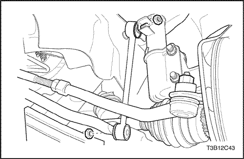
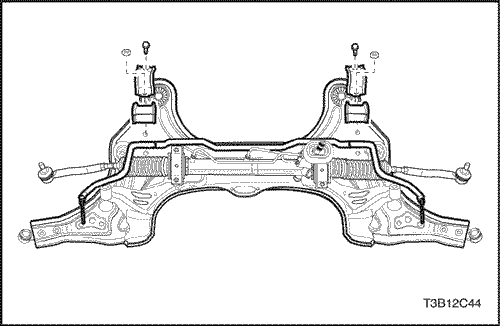
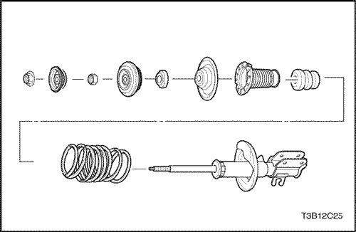
COMPONENT LOCATOR
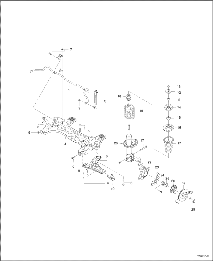
Front Suspension
- Stabilizer bar
- Stabilizer link nut
- Stabilizer link
- Crossmember
- Crossmember nut (front direction)
- Control arm connecting bolt
- Stabilizer bar nut
- Control arm
- Ball joint connecting bolt
- Ball joint
- Piston rod nut
- Washer
- Strut upper nut
- Strut mount
- Bearing
- Spring upper seat
- Spring upper insulator
- Hallow bumper
- Coil spring
- Thrust
- Thrust bracket bolt
- Steering knuckle
- Cover seat
- Wheel bearing
- Retaining ring
- Wheel hub
- Brake disc
- Washer
- Caulking nut
MAINTENANCE AND REPAIR
ON-VEHICLE SERVICE
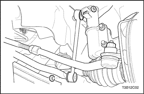
Stabilizer Shaft Link
Removal Procedure
- Lift and suitably support the vehicle, allowing the frontsuspension to hang free.
- Remove the front wheel. Refer to Section 2E, Tiresand Wheels.
- Remove the stabilizer shaft-to-knuckle nut and the shaft-to-link nut.
- Disconnect the stabilizer shaft from the knucle by removing the stabilizer shaft link assembly.
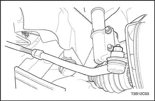
Installation Procedure
- Install the stabilizer shaft into the vehicle.
- Install the stabilizer shaft-to-knuckle nut and the shaft-to-link nut.
Tighten
Tighten the stabilizer shaft link nuts to 50 N•m(37 lb-ft).
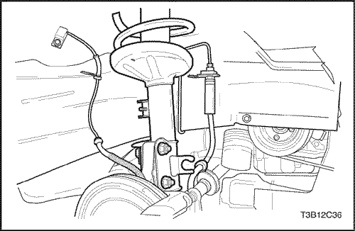
Strut Assembly
Tools Required
KM-507-B Ball Joint Remover
Removal Procedure
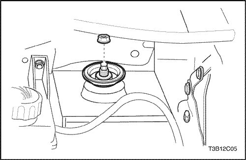
- Loosen the strut assembly -to-body nut that attach the top of the strut assemblyto the vehicle.
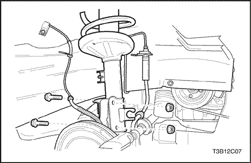
- Raise and suitably support the vehicle.
- Place the jackstands under the frame of the vehicle.
- Lower the vehicle slightly so the weight of the vehiclerests on the jackstands and not on the control arms.
- Remove the wheel. Refer to Section 2E, Tires andWheels.
- Disconnect the brake caliper from the knuckle/strutassembly and support the caliper. Do not hang the caliperfrom the hydraulic brake hose. Refer to Section4D, Front Disc Brakes.
- Disconnect the ABS speed sensor electrical connector,if applicable.

- Remove the ball joint-to-knuckle-strut nut.
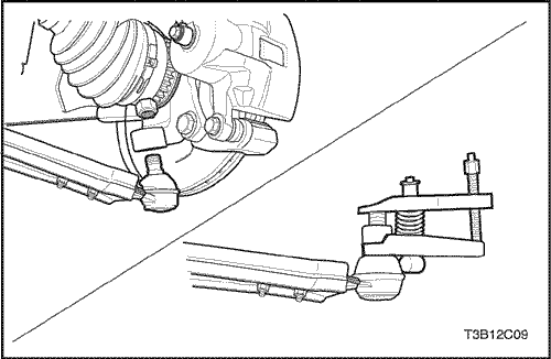
Notice : Failure to use the recommended tool for separatingthe ball joint from the steering knuckle assemblymay damage the ball joint and seal.
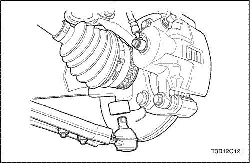
- Separate the steering knuckle assembly from theball joint using the ball joint remover KM-507-B.
- Remove the outer tie rod from the steering knuckleassembly. Refer to Section 6C, Power SteeringGear [Includes Rack & Pinion Gear] or Section 6D,Manual Steering Gear [Includes Rack & PinionGear].
Notice : Take care to prevent the axle joints from beingoverextended. When either end of the shaft is disconnected,the joint can become overextended. This overextensioncan cause the internal components toseparate. This separation can cause joint failure. Usedrive axle joint seal protectors during any service on ornear the drive axles. Failure to use joint seal protectorscan damage the interior joint seal and cause joint failure.
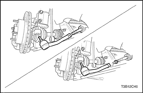
- Push the drive axle shaft from the front wheel hub.
- Support the drive axle.
- Lower the vehicle in order to gain access to thestrut-to-body nuts and the washers.
Notice : Chipping or scratching the spring coating whenhandling the front suspension coil spring can cause thespring to fail.
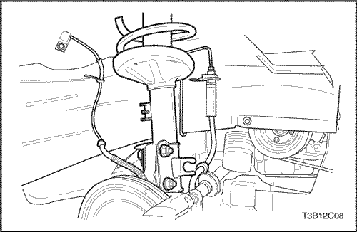
- Remove the strut assembly-to-body nuts.
- Remove the strut assembly from the vehicle.
Installation Procedure
Notice : Chipping or scratching the spring coating whenhandling the front suspension coil spring can cause thespring to fail.
- nstall the strut assembly into the vehicle with the strut assembly-to-body nuts.
Tighten
Tighten the strut assembly-to-body nut to 60 N•m(44 lb-ft).
- Connect the drive axle to the front wheel hub.
- Connect the outer tie rod to the steering knuckle assembly.Refer to Section 6C, Power SteeringGear [Includes Rack & Pinion Gear] or Section 6D,Manual Steering Gear [Includes Rack & PinionGear].
- Connect the ball joint to the steering knuckle assembly.
- Install the ball joint-to-knuckle/strut nut.
Tighten
Tighten the ball joint-to-knuckle/strut nut to 55 N•m (41 lb-ft).
- Connect the ABS speed sensor electrical connector,if applicable.
- Connect the brake caliper to the knuckle/strut assembly.Refer to Section 4D, Front Disc Brakes.
- Install the wheel. Refer to Section 2E, Tires andWheels.
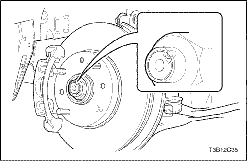
- Install a new drive axle-to-hub caulking nut.
Tighten
Tighten the drive axle-to-hub caulking nut to 300 N•m(221 lb-ft).
- Crimp the caulking nut sleeve onto the drive axleshaft.
Control Arm
Tools Required
KM-507-B Ball Joint Remover
Removal Procedure
- Raise and suitably support the vehicle.
- Place the jackstands under the frame of the vehicle.
- Lower the vehicle slightly so the weight of the vehiclerests on the jackstands and not on the control arms.
- Remove the wheel. Refer to Section 2E, Tires andWheels.
- Disconnect the stabilizer shaft from the control arm by removing the control armlink bolt assembly.
- Remove the retaining clip and the ball joint-to-knuckle/strut nut from the ball joint.
- Disconnect the ball joint from the steering knuckleusing the ball joint remover KM-507-B.
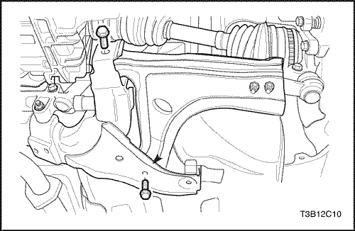
- Remove the control arm front mounting bolt.
- Remove the control arm rear mounting bolts and thebracket.
- Remove the control arm from the vehicle.
Installation Procedure
- Install the control arm onto the vehicle.
- Connect the front of the control arm to the body ofthe vehicle with the front mounting bolt and thewasher.
- Apply a thread sealer to the control arm rear mountingbolts.
- Connect the rear of the control arm to the body ofthe vehicle with the rear mounting bracket and bolts.
Important : Do not tighten the control arm bolts at thispoint.
Notice : Use a new self-locking nut to install the controlarm link bolt assembly. Failure to do so will allow the normalvibration of the vehicle to loosen the nut and damagethe vehicle.
- Install the stabilizer shaft link bolt assembly.
- Connect the ball joint to the steering knuckle.
- Tighten the ball joint-to-knuckle/strut nut.
Tighten
Tighten the ball joint-to-knuckle/strut nut to 55 N•m (41 lb-ft).
- Connect the retaining clip to the ball joint stud.
- Install the wheel. Refer to Section 2E, Tires andWheels.
- Raise the vehicle.
- Place the jackstands under the control arms.
- Lower the vehicle.
Important : The control arms must support the weight ofthe vehicle while the control arm mounting bolts are beingtightened.
- Tighten the control arm rear mounting bolts.
Tighten
Tighten the control arm rear mounting bolts to 110 N•m(81lb-ft).
- Tighten the control arm front mounting bolt.
Tighten
Tighten the control arm front mounting bolt to 110 N•m(81 lb-ft).
- Raise the vehicle.
- Remove the jackstands.
- Lower the vehicle.
Steering Knuckle
Removal Procedure
- Remove the front wheels.Referto Section 2E, Tires andWheels.
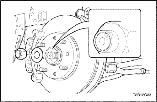
- Remove the caulking nut.
- Remove the tie rod end from the knuckle.
- Remove the control arm ball joint.
- Remove the brake caliper.
- Remove the brake disk.Refer to Section 4D, Front Disk Brakes.
- Remove the ABS wheel speed sensor, if equipped Refer to Section 4F, ABS from the knuckle.
- Remove the backing plate.
- Remove the front strut bolts.
- Remove the knuckle assembly.
Installation Procedure
- Install the knuckle assembly to the front strut with bolt and nuts.
Tighten
Tighten the knuckle assembly to the front strut with bolt andnuts to 100 N•m(74lb-ft).
- Install the backing plate with the screws.
Tighten
Tighten the backing plate with the screws to 4 N•m (3lb-ft).
- Install the ABS wheel speed sensor.
- Install the brake disk and caliper.Refer to Section 4D, Front Disk Brakes.
- Install the control arm ball joint.Refer to this Section, Unit Repair
- Install the tie rod end to the knucke. Refer to this Section.
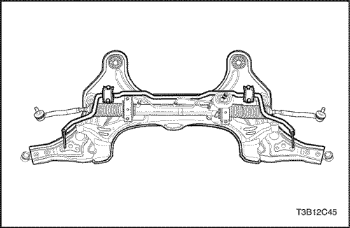
Crossmember Assembly
Removal Procedure
- Remove the front wheels.
- Remove the control arm ball joint and stabilizer shaft link nut (lower). Refer to this Section.
- Remove the tie rod end ball joint. Refer to this Section.
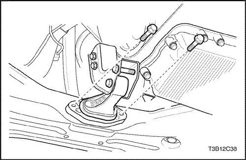
- Remove the engine mounting reaction rod bolts.
- Drain the power steering fluid.
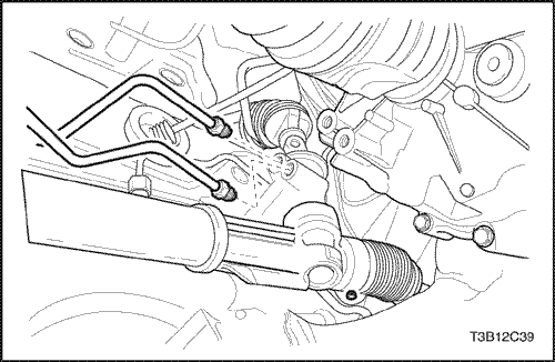
- Remove the power steering pipe fittings.
- Remove the interm shaft lower joint.
Caution : When the engine is hot, do not remove the above parts from the vehicle otherwise, personal injury can be caused by hot components of the vehicle.
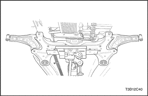
- Remove the crossmember assembly.
Caution : To avoid personal injury or vehicle damage, the crossmember should be supported by jackstand prior to the removal.
- Remove the stabilizer bar, power steering gear set and control arm from the crossmember.
Installation Procedure
- Install the stabilizer bar, power steering gearset and control arm from the crossmember.
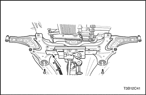
- Install the crossmember assembly front to body nut and the crossmember assembly rear to body bolt.
Tighten
Tighten the crossmember assembly front to body nut and rear to body bolt to 150 N•m(111 lb-ft).
- Connect the interm shaft lower joint and power steering pipe fittings.
Tighten
Tighten the power steering pipe fittings to 22 N•m(16 lb-ft).
- Fill the fluid reservoir with the power steering fluid.
- Inspect for leaks. If there are leaks, correct the cause of the leaks and bleed the system. Refer to Section 6A, Bleeding the Power Steering System.
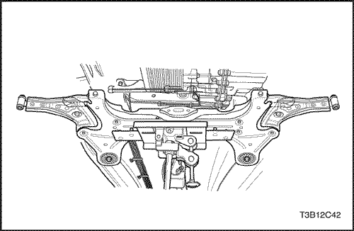
- Install the engine mounting reaction rod bolts.
Tighten
Tighten the engine mounting reaction rod bolts to 60 N•m(44 lb-ft).
- Install the tie rod end ball joint nut.
Tighten
Tighten the tie rod end ball joint nut to 45 N•m(33 lb-ft).
- Install the control arm ball joint and stabilizer shaft link nut (lower). Refer to this Section.
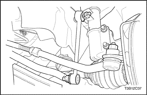
Stabilizer Bar
Removal Procedure
- Remove the crossmember assmbly. Refer to this Section
- Remove the stabilizer bar from the crossmember assembly by unscrewing the u-clamp bolts.
Installation Procedure
- Install the u-clamp bolts to the stabilizer bar.
Tighten
Tighten the u-clamp bolts to the stabilizer bar to 25 N•m(18 lb-ft).
- Remove the crossmember assmbly. Refer to this Section
UNIT REPAIR
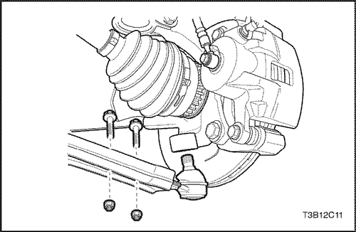
Ball Joint
Disassembly Procedure
- Raise and suitably support the vehicle.
- Place the jackstands under the frame of the vehicleand lower the vehicle slightly so the weight of the vehiclerests on the jackstands and not on the controlarms.
- Remove the wheel. Refer to Section 2E, Tires andWheels.
- Remove the control arm. Refer to "Control Arm"inthis section.
- Remove the ball joint mounting bolts.
Assembly Procedure
- Connect the ball joint to the control arm with the mounting bolts.
- Install the nuts to secure the bolts from below thecontrol arm.
Tighten
Tighten the ball joint-to-control arm nuts to 150 N•m(111 lb-ft).
- Install the control arm. Refer to "Control Arm"in thissection.
Hub and Bearing
Tools Required
500-20 Hex Nut
J-36661-2 Forcing Screw
J-37105-B-1 Support Bridge
J-37105-B-2 Bearing Adapter
J-37105-B-3 Hub Adapter
Disassembly Procedure
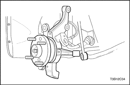
- Remove the drive axle from the front wheel hub. Referto "Strut Assembly"in this section.
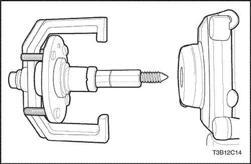
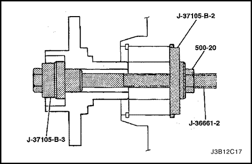
- Remove the wheel hub with the support bridgeJ-37105-B-1, the hub adapter J-37105-B-3, the hexnut 500-20, and the forcing screw J-36661-2.
- Remove the brake shield. Refer to Section 4D, FrontDisc Brakes.
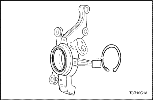
- Remove the outer snap ring.
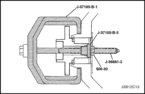
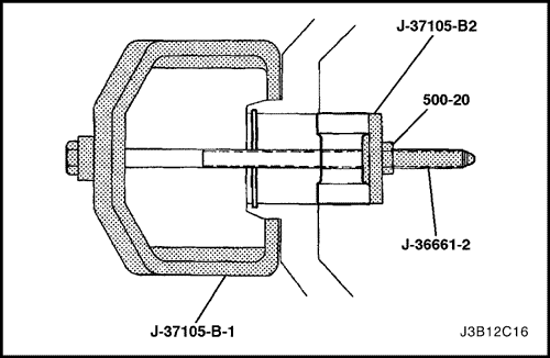
- Remove the wheel bearing with the support bridgeJ-37105-B-1, the bearing adapter J-37105-B-2, thehex nut 500-20, and the forcing screw J-36661-2.
- Clean the bore of the knuckle.
Assembly Procedure
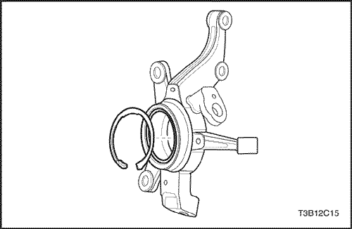
- Install the outer snap ring and push the wheel bearinginto place with the support bridge J-37105-B-1, thebearing adapter J-37105-B-2, the hex nut 500-20,and the forcing screw J-36661-2.
- Install the brake shield. Refer to Section 4D, FrontDisc Brakes.
- Push the wheel hub into place with the hub adapter J-37105-B-3, the bearing adapter J-37105-B-2, the hex nut 500-20, and the forcing screw J-36661-2.
- Install the drive axle into the front wheel hub. Refer to "Strut Assembly" in this section.
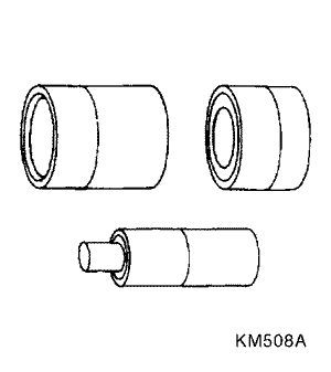
Control Arm Bushings
Tools Required
KM-508-A Remover/Installer
KM-158 Remover/Installer
KM-307-B Removal Plate
Disassembly Procedure
- Remove the control arm. Refer to "Control Arm"inthis section.
- Press off the rear bushing using a press, the remover/installer KM-158, and the removal plate KM-307-B.
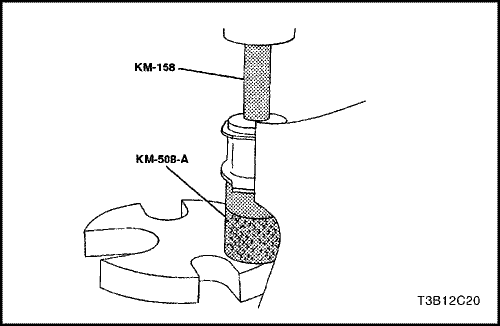
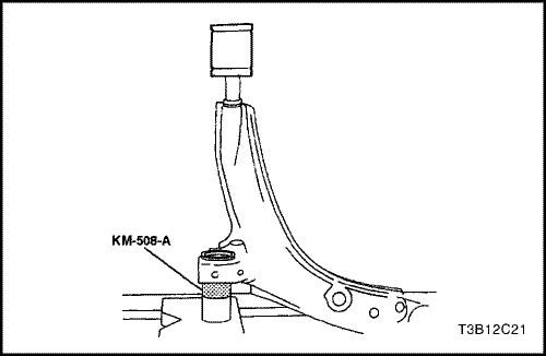
- Press out the front bushing using the remover/installerKM-508-A, and the remover/installer KM-158.
Assembly Procedure
- Coat the control arm rear shaft with a multipurposelubricant. Refer to Section 0B, General Information.
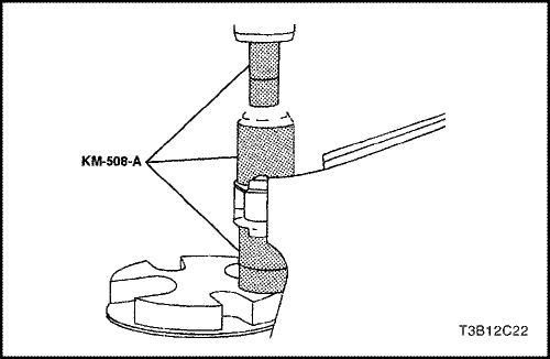
- Press the rear bushing onto the shaft. The flat of thebushing must be on the top side, the same as the balljoint. Use the remover/installer KM-508-A to supportthe control arm.
- Coat the outside of the front bushing and the inside ofthe lower control arm with a multipurpose lubricant.Refer to Section 0B, General Information.
- Press the new bushing into the control arm from theback to the front, using the remover/installer KM-508-A.
- Center the bushing.
- Install the control arm. Refer to "Control Arm" in thissection.
Front Strut Assembly
Tools Required
KM-329-A Spring Compressor
J-42468 Front Strut Mount Nut Wrench
Disassembly Procedure
- Remove the strut assembly. Refer to "Strut Assembly"in this section.
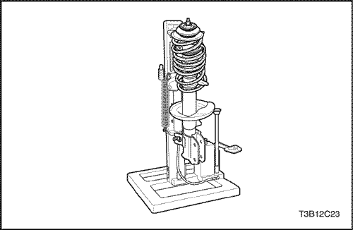
- Fasten the strut assembly to the spring compressor KM-329-A.Make sure the hooks are seated on the strut springproperly.
- Compress the front spring with the front spring compressorKM-329-A.
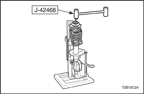
- Use an open end wrench to hold the threaded pistonrod while removing the piston rod nut with J-42468 front strut mount nut wrench.
- Remove the strut mount, strut bearing, spring upper seat, spring upper insulator, hallow bumper, coil spring and strut step by step.
Important : Record the position of the front spring seat relative to the strut assembly-to-knuckle bracket. Place the front spring locator back in the same position during assembly.
Assembly Procedure
- Install the lower spring insulator and the spring.
- Comopress the spring using the spring compressor KM-329-A.
- Install the strut mount, strut bearing spring upper seat, spring upper insulator, hallow bumper, coil spring and strut step by step.
- Use an open end wrench to hold the threaded piston rod while installing the piston rod nut with J-42468 front strut mount nut wrench.
Tighten
Tighten the piston rod nut to 60 N•m (44 lb-ft).
Important : Locate the coil spring to the original position on th coil spring seat. Check the installation condition of the coil spring.
GENERAL DESCRIPTION AND SYSTEM OPERATION
Front Suspension
The front suspension for this vehicle is a combinationknuckle/strut and spring design.
The control arms pivot from the body. The lower controlarm pivots use rubber bushings. The upper end of thestrut is isolated by a rubber mount and contains a bearingto allow the wheel to turn.
The lower end of the steering knuckle pivots on a balljoint bolted to the control arm. The ball joint is fastenedto the steering knuckle with a nut, and to the lower controlarm with rivets.
When servicing the control arm-to-body attachment andthe stabilizer shaft-to-body insulators, make sure the attachingbolts are loose until the control arms are movedto the trim height, which is curb height. Trim height is thenormal position to which the control arms move whenthe vehicle is sitting on the ground. Refer to
"GeneralSpecifications"in this section.